Instron

r値とn値を決定する際の課題

Metals

r値とn値を決定する際の課題

金属薄板の製品開発は、現在、成形性に対する影響を最小化しつつ、如何に強度を増加するか、という要求に牽引されています。強度と成形性の間には古典的なトレードオフがありますが、金属薄板メーカーは、著しく強度が改善されているうえに、成形性低下を最小化した、これまでにないハイグレード金属薄板を発表しています。より薄く軽い材料を自動車生産に用いることにより、走行距離あたりの合計排ガスを削減できるので、自動車産業が最も熱心に高強度化を推進しています。塑性ひずみ比(r値)とひずみ硬化指数(n値)は、これらの製品の成形性を決定する、重要な機械的性質です。

ひずみ測定の課題

r値とは何でしょうか?  -塑性ひずみ比

n値とは何でしょうか? -ひずみ硬化指数

引張試験の中で、このような成形性特性は、Bluehill Universalソフトウェアを用いて自動的に測定されます。n値を決定するには、降伏点以降、軸方向ひずみを測定する必要があり、特定のひずみで、または特定のひずみ間でn値を決定します。伸び計の精度は、少なくとも高い伸び領域に対応できなければなりませんが、金属の引張試験に関する主要な規格は、高い伸び領域で決定される計算に対して、高い精度を要求していません。従来の接触式伸び計は、試験途中で取り外すように設計されていて、全伸び領域をカバーするには限界があります。高性能非接触式ビデオ伸び計 (AVE 2) やAutoXBiax(自動接触式伸び計)等の最新技術では、試験の最後までひずみ測定ができ、高精度の結果を確保できます。

金属薄板メーカーは、主要な製品合格基準として、塑性ひずみ比(r値)を適用することがよくあります。もし、r値が低い場合には、その金属薄板は不合格になります。従って、塑性ひずみ比測定の精度は重要です。r値の決定には、軸方向のひずみ測定に加えて、横方向のひずみも測定されなければなりません。従来は、このために2つの両立するクリップ式伸び計が必要であり、オペレータは確実な装着と適正な場所を確保しなければなりません。 

軸方向ひずみ測定に自動式伸び計を使用することにより、生産性が改善します。さらに、軸方向と横方向の両方に使用すれば、改善効果はいっそう大きくなります。自動接触式伸び計は、2つのクリップ式伸び計に比べて、試験あたり30%以上速くなります。伸び計が常に試験片の同じ場所に装着されるので、再現性も向上します。

r値とn値の試験に対する伸び計の選択:

strain-measurement.jpg

下図は、高性能ひずみ測定ソリューションを使う有効性を示しています。伸び計間で不変の所用時間は、試験片形状測定と、試験片挿入、試験時間に関するものです。伸び計の設定時間は変動し、また、クリップ式伸び計は、激しい破断を伴う高強度鋼(ハイテン材)に対しては取り外されなければなりません。

timecomparisonchart.png

結果の再現性に関わる課題

試験中には、試験結果のばらつきや再現性に影響を与える、多くの要因があります。r値とn値を決定する際のばらつきに関する、最も一般的な原因は: (通常、r値はn値よりも、これらの変動に敏感です。):

伸び計を試験片に装着する場所に依存して、試験結果は変動します。下記に、4つの異なる横方向標点距離を用いた試験片を、デジタル画像相関ソフトウェアを用いて解析したものを示しています。伸び計の装着位置により、異なった横方向ひずみ値が示されています。これは、r値の計算に差異をもたらします。手動で伸び計を装着する場合、横方向ひずみ測定に影響を与えます。

ひずみ制御の課題

Metals

The Challenges of Strain Control

Why Strain Control?

Some of the mechanical properties of metals are affected by the speed of the test and are therefore ‘strain-rate sensitive’. In 2009 one of the primary metals testing standards, ASTM E8, was updated to include a method based on controlling the strain rate on the specimen. Prior to this change tests could only be run in stress control or crosshead speed control, where the overall machine stiffness can affect the speed on the specimen and cause differences in results. When testing strain-sensitive materials with crosshead speed control, the allowable test speeds can cause more than a 10% difference in proof stress results from testing at the slowest and fastest rate allowed in ASTM E8/E8M and ISO 6892-1.

Running a test in strain control, however, allows the test to run at different speeds during testing in order to compensate for machine compliance and maintain a constant strain rate on the specimen. This method increases throughput by reducing the overall test time required. It can also save time and prevent specimens being wasted to tune the test, because unlike the stress control method, closed loop strain control does not require multiple trial and error adjustments to the crosshead speed to ensure that the strain rate is in compliance with the testing standards.

Requirements to Achieve Closed-Loop Strain Control

In order for a testing system to achieve closed-loop strain control, certain requirements must be met. In all cases, it is important that the test machine and extensometer be isolated from any sudden or repetitive vibrations or shocks, as this could cause interference in your testing. 

An extensometer is a high-precision device used to measure deformation of a specimen. Extensometers remove system compliance from the strain measurement calculation, but it's important that the chosen extensometer is appropriate for the travel length of the specimen and has a suitable ratio of parallel length to gauge length.

clip-on-metals1.jpg

Grips need to securely hold the specimen during testing, preferably with high stiffness and minimal compliance. The graph shows how different types of gripping devices can effect the system stiffness, and how a machine in strain control would need to compensate.

Grips

The load frame of the testing system needs a precise and stable drive system with high stiffness. To the right shows a stress strain curve on nominally similar materials - one testing on a high stiffness frame and the other on a low stiffness frame. Using an estimated strain method calculation, both tests are run at a constant crosshead speed of 2.25 mm/min. There was a 21% difference in 'specimen speed' (expressed in mm/min), which lead to a 5% difference in the yield result.

loadframe.jpg

This graph shows the specimen speed difference between a 'stiff' system and a less stiff system. At the start of the test it is shown that the crosshead movement is transferred into strain on the specimen very quickly, whereas on the weaker system it takes longer. This is due to the machine/load cell/grips deflection, which causes that movement to not be transferred to the specimen. If both machines were using strain control then the results would be much more comparable, but the control will likely be more challenging on the weaker system.

specimenspeed.jpg

Machines capable of strain rate control require a responsive controller and a precise and stable drive system in order to maintain the tolerances required by the testing standard. Some machines are advertised as being able to achieve this method but require the user to manually tune the gain settings of the controller, which can be difficult for even the most experienced system operator.

software-and-controller.jpg

Specimen

A proportional specimen and a proportional gauge length extensometer are ideal. In reality, a specimen with good gauge length to parallel length ratio is well suited to minimize the strain seen outside of the gauge length, allowing the control to be more stable. If your specimens vary from discontinuous yielding to continuous yielding, it is important to change control methods for each type. As local yielding can occur outside of the gauge length on discontinuous yielding material, it is impossible to control from the strain feedback and should be in crosshead speed control during yield point elongation [YPE/Ae].

specimens.jpg

Advantages of Closed-Loop Strain Control

✓ More repeatable and comparable results - test results are reliable from machine to machine
✓ Improved efficiency - time per test is minimized and setup time reduced
✓ No need to tune with a specimen when using a testing system with 6800 Series controller electronics

焼結粉末金属の動的曲げ疲労試験ショウケツムスフンマツキンゾクドウテキマヒロウ

Metals

焼結粉末金属の動的曲げ疲労試験

粉末焼結超硬合金から製造された工具などの多くの工作機械用の工具材料は、高い剛性(>500 GPa)をもつ極めて強度の高い材料(典型的な圧縮強さは5 GPa)です。多くの場合、この材料は製造コストが高いか、あるいは小さいサンプルサイズでしか利用できません。

効果的な試験システムでは、非常に低い荷重と変位レベルにおいて高い周波数を維持しながら繰り返し荷重を適用できることが望まれます。インストロンのElectroPuls試験装置は、引張圧縮曲げ、及び疲労に関する金属及び超硬合金の試験で必要となる精度と再現性を提供します。正しいロードセルとグリップの正確な組立と選択により、ElectroPuls試験装置は、この特定の試験に必要な1000 N以上の荷重における安定した荷重とならんで、長時間にわたる1ニュートンより低い荷重レベルにおける安定した荷重を適用する、用途の広いプラットフォームを提供します。

低荷重における試験を行う際に適切な測定精度と制御を保証するためには、正しいロードセルの選択は不可欠です。高い周波数で使用する場合、インストロンのDynacellロードセルの積分イナーシャ補正機能は、荷重読取り値のイナーシャ誤差を確実に最小化します。

インストロンでは、WaveMatrix動的試験ソフトウェアと、英国国立物理研究所(NPL)から提供された小型の4点曲げ取付け具を用いて、これらの超硬合金に関するさまざまな熱処理Vノッチ試験片の試験を行いました。

このソフトウェアは、試験を手早くセットすることが可能であり、またそのデータ収集機能の用途は幅広いため、正確な破壊事象の記録を含めて、CSVフォーマットで正確で関連性の高いデータ収集を提供しました。多数の試験にわたって、一貫性をもった再現性ある試験結果を提供することができました。

資料

ElectroPuls

数十億サイクルにわたる試験を10年以上実施してきたElectroPulsシステムは、特許取得のリニアモーター技術を使用した確立された材料試験機です。最大20 kNのモデル容量を持つElectroPulsシステムは、低速の静的試験と数百ヘルツの能力を持つ高周波動的疲労試験を提供します。リニア・トーションモデルは、材料とコンポーネントの2軸試験のための特許取得のアクチュエーターを特徴としています。

  • 製品
  • 06/05/2019
  • 3.73 MB

Solutions for Reinforcement Bar Testing

鉄筋の試験ソリューション

鉄筋試験の課題に対するインスロトンのソリューション

Metals

鉄筋の試験ソリューション

世界の建設需要は、2025年までに70%以上成長し、15兆ドルに達すると予測されています。成長する分野としては、新しい橋梁や道路、ダム、トンネル、競技場等が想定されています。これらの全ての構造物では、引張強度を向上させるため、コンクリート中に埋め込まれる鉄筋(リバー)が必要になります。

様々な鉄筋の製品規格は、複数の国際試験規格と連携しており、試験ガイドラインは広く知られています。インストロンの試験機はISO 6892-1:2009ISO15630-1、またASTM E8M: 2013A370 A615、 AC133、BS 4449、GB 1499、JIS G3112の規格に準拠しています。

鉄筋の引張試験の要求事項は、製品と試験規格の補遺として広く用いられており、ユーザーによってよく誤解される分野に関して、説明がされています。インストロンのウェブサイト上のセミナー「A Webinar: Challenges of Rebar Testing 」もご参照ください。

鉄筋の試験には、多くの課題があります。試験片が不規則または湾曲していること、引張試験における破断の激しさ、ひずみや伸びの測定、引張試験結果の再現性と精度の確保、曲げ試験、鉄筋継手のサイクル試験などです。

下記サイトからも、試験効率と生産性を向上、オペレータの安全性の向上のためにお役立ていただけるインストロンの情報をご覧いただけます。

slideshare youtube Download PDF

Instron (Translated to fr)

Metals

Efficiency of Sheet Metal Testing

Globally, testing of sheet metal material is typically performed using a ‘traditional’ testing setup requiring a large amount of operator input. By utilizing some cost-effective changes, the efficiency of your testing regime can be greatly improved.

Setup for Efficiency

Using the latest Bluehill® Universal software, small modifications can be made to the testing protocol to gain incremental improvements. These could include creating a prompted test method to ensure only valid information is prompted for each test, minimizing wasted time needed to monitor or change non-value inputs.

Alternatively, integrating new or existing specimen measuring devices to work autonomously with the software instead of manually inputting values can save a great deal of time.

Cost versus Effectiveness

Switching from manual grips to either pneumatic or hydraulic grips will automate the gripping process. This significantly reduces the time it takes to close the upper and lower grip, and also ensures less variation in test results are caused by operators manually clamping each grip.

Automatic extensometers can save a large amount of time for each test since they require no manual setup between tests. Some extensometers may need to be removed during the test to prevent damage to the device. Therefore, time savings will also be achieved by using an automatic device that is designed to remain on the specimen through fracture or automatically removed.

The graphic below demonstrates a typical test cycle time comparing only the effect of extensometer choice:

Automatic Extensometers can save you time

Struggling to justify new purchases? Talk to Instron® to see where the most cost-effective changes could be made with your existing equipment.

Efficiency of Sheet Metal Testing

Metals

钣金测试的效率

世界的に見ても、金属薄板材料の試験は通常、オペレータの多くの労力を必要とする、「従来からの」試験法を使って実施されています。費用効果のある改善を適用することにより、試験システムの効率を大幅に向上することが可能です。

Setup for Efficiency

最新のBluehill ソフトウェアを使うと、試験手続きに細かい修正が施されるので、改善を積み上げていくことができます。この中には、各試験において重要な情報のみ指令され、数値以外の入力を確認または変更するための無駄な時間を最短化する、迅速な試験手続きを作成することも含まれます。

試験片寸法測定値を手動で入力する代わりに、ソフトウェアと自律的に連動できる新規や既存の試験片測定装置を導入することにより、多くの時間を節約することができます。

Cost versus Effectiveness

手動グリップから、空気圧式または油圧式グリップに変更することにより、グリップ工程を自動化できます。上側および下側グリップを締め付けるのに要する時間を著しく削減するとともに、オペレータが手動で各グリップをクランプすることにより発生する、試験結果のばらつきを確実に低減します。

自動伸び計は、試験間で手動設定が不要なので、各試験について多くの時間を節約できます。伸び計によっては、損傷を防止するため、試験途中で取り外すことが必要です。自動伸び計は、破断まで試験片に装着できるよう設計されているか、自動的に取り外せるようになっていますので、ここでも時間を節約することができます。

下図では、標準的な試験サイクル時間が、伸び計の選択だけで、どのような影響を受けるかを比較しています:

Automatic Extensometers can save you time

新規購入の承認を得る方法をお悩みでしょうか?お客様の現在の装置のどの部分で、費用効果の最も高い改善が可能かインストロンまでお問い合わせください。

Spring Testing 101

Metals

Spring Testing 101

written by Landon Goldfarb

Springs are common items used in thousands of applications, from the production of simple consumer goods to the automotive, aerospace, and biomedical industries. Regardless of a spring's end use application, extensive testing is required to ensure that they exhibit the desired mechanical qualities - namely stiffness and strength - that allow them to perform successfully. There are three primary types of springs designed for different types of applied force: compression, tension, and torsion. This guide will specifically look at helical compression springs, because they make up the majority of testing inquiries.

different types of springsKey Properties of Springs

There are many factors that can affect a spring’s properties, including material type, wire diameter, pitch, number of coils, and inner/outer diameters. In order to reach the optimal set of working parameters, manufacturers will evaluate the springs with a universal testing machine to see if any of these factors have altered the final product. Universal testing systems can help characterize these properties, including the spring constant, free height, and solid height.

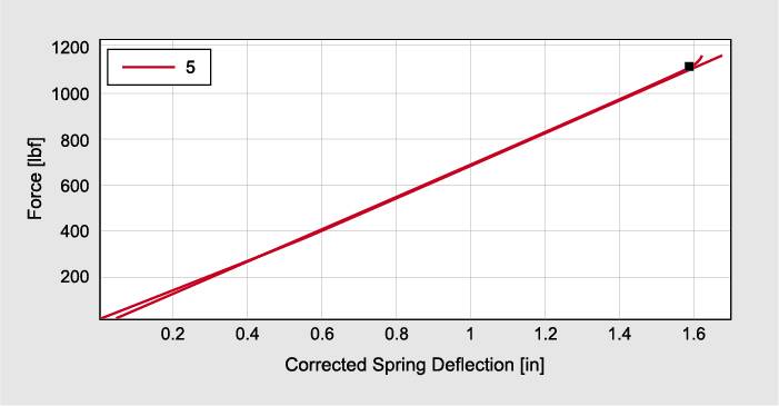
  • The spring constant is determined following Hooke’s law, a theory that asserts the deformation of an elastic object is proportional to the stress applied to the object. The spring constant, often denoted as k, is the proportional factor between the force and displacement. In practice, this can be calculated by finding the slope of the force-displacement curve.
  • The free height of a spring is often calculated as the measured spring height after applying a small preload to ensure that the ends have come into full contact with the loading surface. This preload value can vary depending on the stiffness of the spring.
  • The solid height is measured as the height at which the coil gap reaches zero. It is important to remember this height is often never attained in actual use of the spring, but is important for understanding the force and displacement limits for the end product.

spring testing terminology

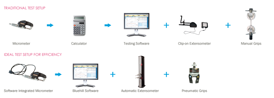
Test Setup and Method Development

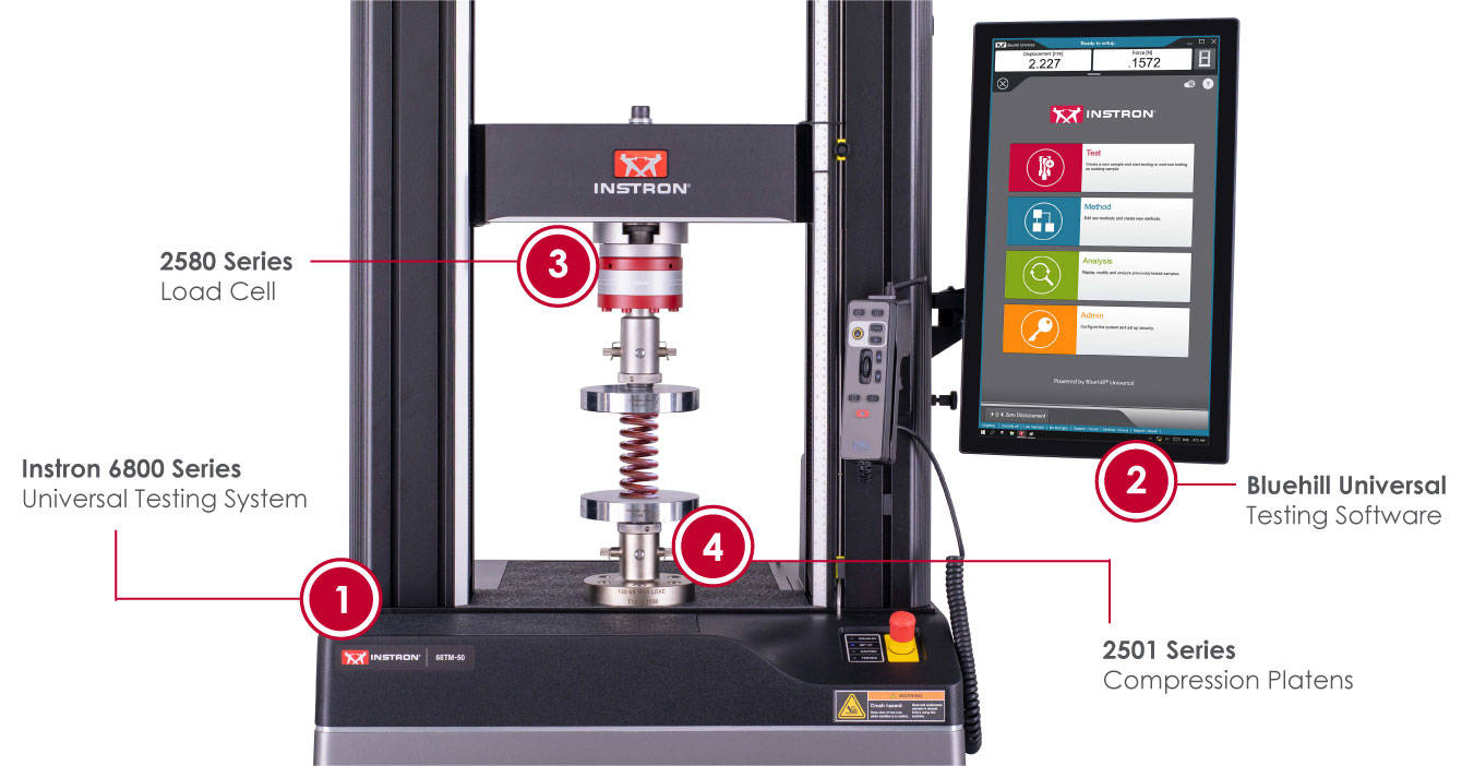
Instron’s new 6800 Series systems are ideal for simple tensile and compression testing requiring only unidirectional force analysis. The system capacities range from 500 N to 300 kN and are capable of testing springs of most common sizes. The 6800 Series utilizes a feature called Auto Positioning, which leverages an absolute encoder to create and save global system configurations. This ensures that an operator can be confident that the fixtures will always move to the correct starting position, depending on the measured spring height.

Using the rich feature set of Bluehill Universal, a method can be created to accommodate helical compression springs regardless of size or stiffness. The operator inputs are configured to require the measured spring height, which is used to determine where the upper platen should be positioned before the test. Using Auto Positioning, the system can be set up to require the platen to always move to a set distance above the measured spring height, allowing the operator to easily place the spring between the platens. This distance can be made greater if the operator needs to access a locating rod or feature to set the spring in place.

spring testing system setup

Measurements

Most manufacturers will use a set preload before determining the free height of the spring. The deflection realistically should not begin until the free height is reached, as this will provide the most accurate force deflection profile possible. Within the Test Profiler workflow in Bluehill Universal, an initial “Ramp to Free Height” step is utilized in order to reach the preload value. At the conclusion of this step, a variable is set equivalent to the displacement at that moment. A virtual measurement subtracts this variable from the displacement to create a “Corrected Spring Deflection,” which will artificially zero the deflection after reaching the free height.

Test Control

Spring testing is typically performed using a monotonic test with an end-of-test criteria. The test rate is manufacturer-dependent and will depend on the end use of the spring. The primary challenge in setting up a spring test is determining when to end the test. The standard options are to use a set load or deflection to indicate the end of the test, but this can be an imprecise method that needs to be modified for each spring sample, and neglecting to set it properly could result in damage to the spring or the testing machine. Some precision machined springs can cost thousands of dollars per part and cannot afford to be damaged during testing. The key to creating a universal end-of-test criteria is to use the live force rate, or the derivative of the force measurement over time. The underlying logic is that a perfect spring will have a near constant force rate during the deflection, which will exponentially increase once the solid height is reached. While deflecting, the force rate should be modeled by the following equation:

Force Rate ((lbfover min)) = Spring Constant ((lbf over in)) * Test Speed ((in over min))

This equation falls apart once the solid height is reached, and the slope of the force rate approaches a vertical line as the spring becomes infinitely stiff. To end the test, a measurement is performed indicating when the force rate is equivalent to twice its measured value early in the spring travel. This measurement will calculate regardless of the spring stiffness and does not require modification for different spring sizes. After this criterion is met, the crosshead will automatically return to the starting position, allowing for easy removal of the specimen.

Results

The reported results can be adjusted based on the customer's preference, but will often consist of the spring constant, free height, solid height, and the force at the solid height. As mentioned earlier, a segment slope is used to determine the spring constant on the force-deflection curve. The graph below shows the curve as well as the applied slope line. The marker at the top of the graph indicates the solid height time. This can be visually confirmed considering it is also the inflection point of the curve transitioning to a higher slope.

corrected spring deflection graph

The free height is determined by capturing the displacement at the preload value and then subtracting it from the measured spring height using a user calculation. The solid height is somewhat more complex, and is identified by analyzing the curve of the force rate versus time. As mentioned earlier, the force rate will plateau and then change drastically once the solid height is reached. The intersection point of those two approximated slopes is the calculated time at which the solid height is reached. From that time, we can determine the actual height of the spring as well as the force required to reach solid height.

spring testing results