ELECTRONICS AND MICROELECTRONICS TESTING
With over 75 years of experience and more than 75,000 testing systems supplied worldwide, Instron is a global leader in the materials testing industry. For decades we have partnered with top innovators in the consumer electronics industry to address testing challenges introduced by new technology such as longer-lasting, fast-charging batteries; innovative displays that flex and fold; devices with increasing touch capabilities; high-density packaging that increase portability; and much more. As part of our partnership, we’ve designed our testing systems with flexibility in mind, making it easier to adapt our systems to test cutting edge technology for years to come.

- Challenges and Solutions for Testing Consumer Electronics
- Challenges and Solutions for Testing Microelectronics
- Mechanical Testing of Electric Vehicle Batteries White Paper
- How To Choose the Right Test Machine for Your Electric Vehicle Battery Application E-Guide
- MIL STD 883: Department of Defense Test Method Standards for Microcircuits
- JEDEC JESD22B113
- EN 14477 Puncture Resistance of Flexible Packaging Material
RECOMMENDED ACCESSORIES
For Testing a Wide Range of Electronics and Microelectronic Components
Instron offers a full spectrum of electromechanical universal testing systems to meet the low to mid-force testing needs of electronics and microelectronics manufacturers. The 68SC single column systems can test forces as low as 0.02 N up to 5 kN, while the 68TM dual column systems have a testing range up to 50 kN. Each of these systems can be equipped with a wide range of accessories to perform tensile, compression, bend, peel, and shear tests. Instron’s Engineered Solutions Group is also available to develop custom fixturing to accommodate abnormal specimen shapes and sizes. The dual column testing frames are available in custom widths and can be outfitted with heating and cooling chambers for temperature testing.

| Test Smarter | |
|---|---|
| 1) | Test All Your Products on One Machine Class-leading load cell accuracy down to 1/1000 of the load cell capacity |
| 2) | Simple to Use Touch-operated Bluehill® Universal software guides users through entire testing process with step-by-step instructions |
| 3) | Consistency in Testing Test methods in Bluehill Universal are easy to transfer from system to system and lab to lab |
| 4) | Test at Temperature Standard solutions from -100°C to +350°C compatible with dual column test frames |
| 5) | Improve Throughput Standard test systems can be outfitted with a range of automation solutions |
| 6) | Grip All Specimen Types & Geometries Wide range of interchangeable grips and fixtures for testing everything from tiny microelectronic assemblies to final products |
| 7) | Adaptable Systems can be adapted to accommodate custom fixturing |

High testing volumes can be made more manageable by incorporating some degree of automation. This can include everything from automated specimen measurement devices to automated XY stages and completely automated robotic testing systems. Our dedicated team of experienced automation engineers work with you to develop a system that meets your throughput requirements.


RECOMMENDED SYSTEMS
To Perform the Most Common Test Types for Electronics and Microelectronics

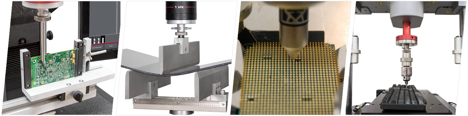
Instron table model universal testing machines can perform tensile, compression, bend, peel, shear, and other mechanical tests on materials, components, and products to ASTM, ISO, and other industry standards.

Instron ElectroPuls® systems with force ranges from 1 kN to 10 kN are ideal for dynamic testing of electronics and microelectronics.

Drop towers qualify the impact resistance of materials, components, and final products and are available from basic un-instrumented to fully instrumented systems with ultra-high speed data acquisition. Learn how drop towers can be used for tensile impact testing for high strain rate measurements.

Instron’s worldwide service and support team is committed to helping you maintain your investment regardless of your location. Dedicated to keeping our customers operating at peak efficiency, Instron has more than 250 accredited service personnel around the globe who have trained extensively on Instron systems. Our technicians are ready to answer your questions, provide training, install systems, repair and upgrade existing machines, provide calibration and verification services per NIST traceable standards, and make sure your equipment complies with global testing standards.