A Guide to Cyclic Fatigue Testing of Tibial Tray Components in accordance with ASTM F1800 and ISO 14879
Written by Toby Lane
A summary of the common parameters in the standardsFatigue fracture of knee tibial trays has been one of the most commonly reported failure mechanisms of Total Knee Replacements (TKR). It is caused by loss of underlying bone support resulting from biological reactions, such as wear-induced osteolysis. Under these conditions, the tibial tray becomes mechanically unstable, and cyclic loading imparted by normal walking causes fatigue cracks, ultimately leading to catastrophic failure.
We recommend that you review ISO 14879-1 and ASTM F1800 to fully understand the full requirements.

TEST FIXTUREA clamping fixture is used to secure one half of the tibial tray, simulating a fully supported condyle. The other unsupported condyle is then subjected to physiologically representative loading. By using our patented Dynacell™ load cell, dynamic inertial errors (such as those caused by the fixturing and from hydro-dynamics that result when testing in an environmental bath) can be removed, allowing for a more accurate measurement of load being applied to the specimen.
TEST FIXTURETibial tray tests are carried out in force control with the peak force set to 10% of the maximum force the tray can withstand. 900N is a typical value, but depending on the material, the force used is often in excess of 2000N. The number of cycles is determined by the user, but a typical value is 10 million. 10 Hz is the prescribed frequency for this test (although higher frequencies can be used if evidence that test results match those obtained at 10Hz is provided). Tests are run until either the spacer thickness is reduced to 3 mm or fragments, the tibial tray fails, cracks are detected in the specimen following visual inspection or non-destructive inspection or finally, if the maximum number of cycles is reached.
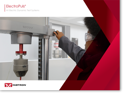
ElectroPuls
With more than ten years of running tests over billions of cycles, ElectroPuls systems are the established materials testing machines using patented linear motor technology. With model capacities up to 20 kN, ElectroPuls systems offer slow-speed static testing and high-frequency dynamic fatigue testing with hundreds of hertz capability. The Linear-Torsion models feature a patented actuator for bi-axial tests on materials and components.
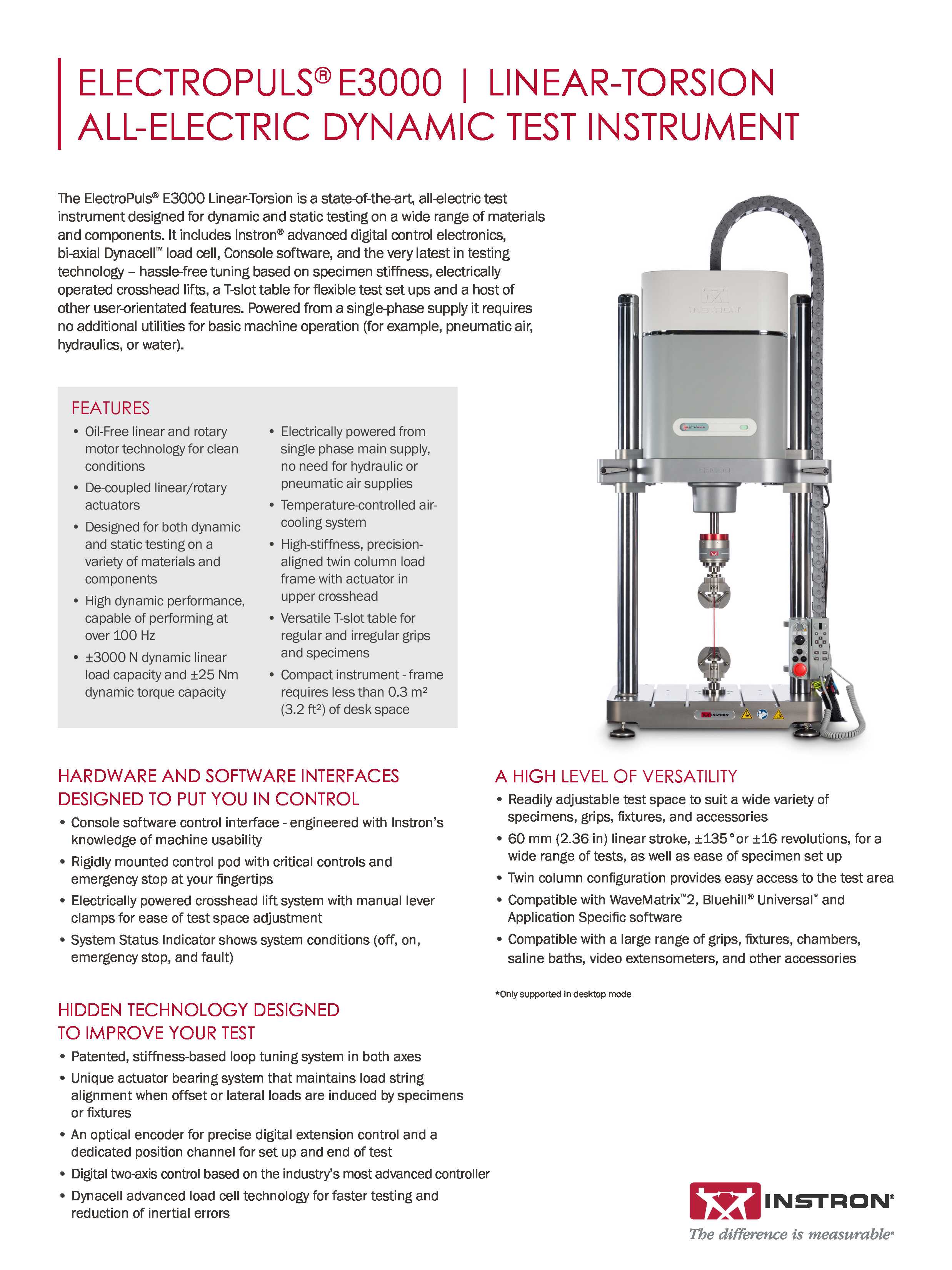
ElectroPuls E3000®
The ElectroPuls® E3000 Linear-Torsion is a state-of-the-art, all-electric test instrument designed for dynamic and static testing on a wide range of materials and components. It includes Instron® advanced digital control electronics, bi-axial DynacellTM load cell, Console software, and the very latest in testing technology – hassle-free tuning based on specimen stiffness, electrically operated crosshead lifts, a T-slot table for flexible test set ups and a host of other user-orientated features. Powered from a single-phase supply it requires no additional utilities for basic machine operation (for example, pneumatic air, hydraulics, or water).