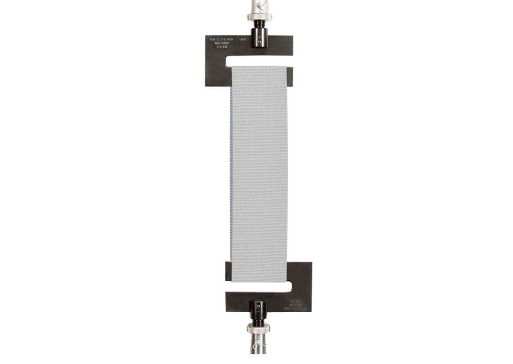
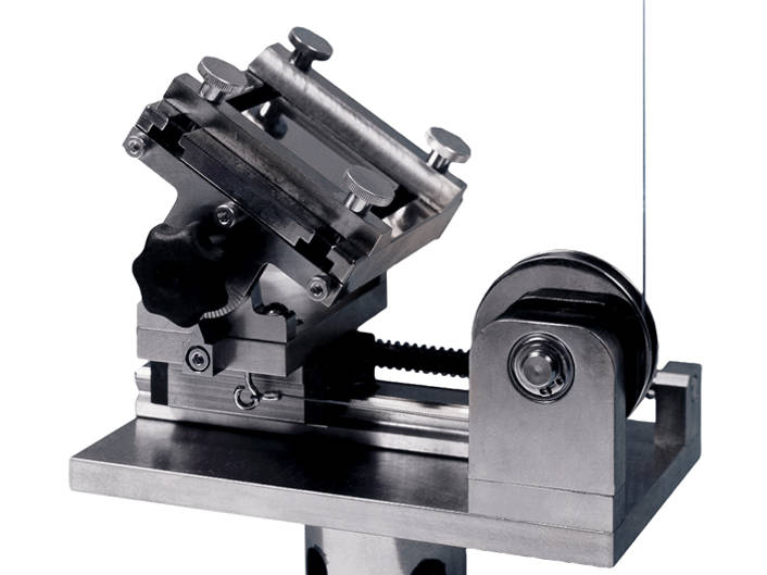
Guided-Bend/Weld Bend Test Fixture; specimen width to 76 mm (3.0 in)

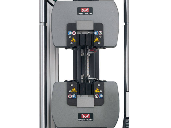
Two types of bend fixtures are available for evaluating the ductility of plate specimens and welded ferrous and non-ferrous materials. The main difference between the two fixtures is in the base, the guided bend test fixture has a fixed span base, while the weld bend test fixture has an adjustable span base.
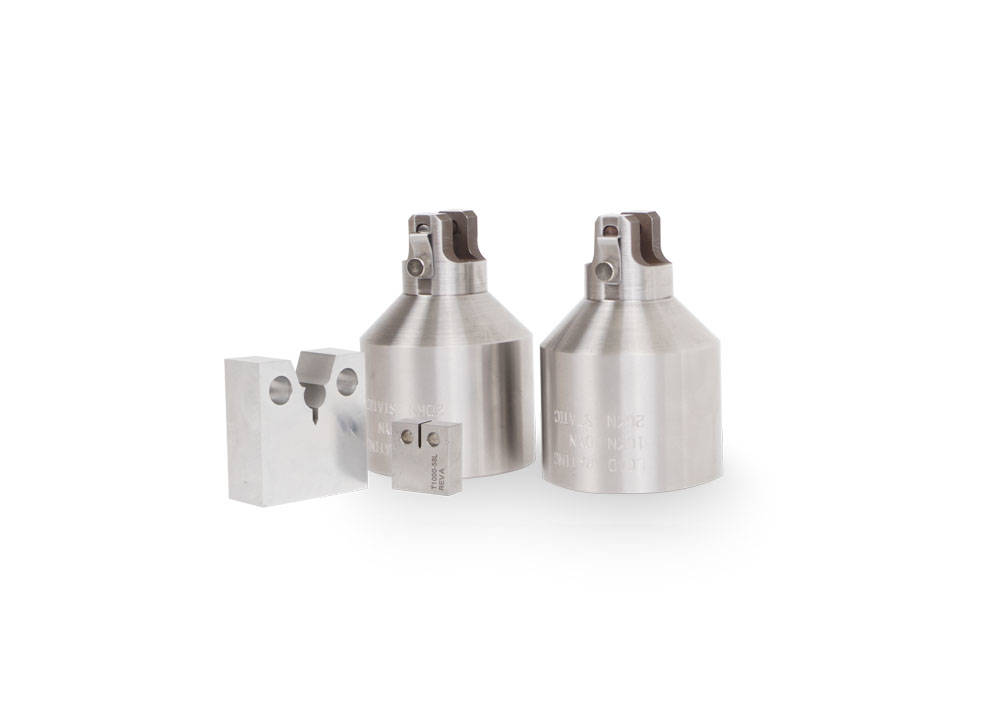
Both fixtures use plungers or loading struts with a fixed diameter nose for testing a particular specimen thickness. The plungers are attached to the adjustable crosshead using the grip bumper plate or a threaded adapter.
The base is equipped with a dowel hole in the center so that it can be doweled to the compression table and kept from sliding during a test. This also will maintain the alignment of the plunger in relation to base so that the force is applied in the center of the span.
The hardened rollers in the base are captured but free to rotate to allow the specimen to slide as the plunger moves between the rollers. The depth of the base will typically allow up to a full 180 degree bend in the specimen.
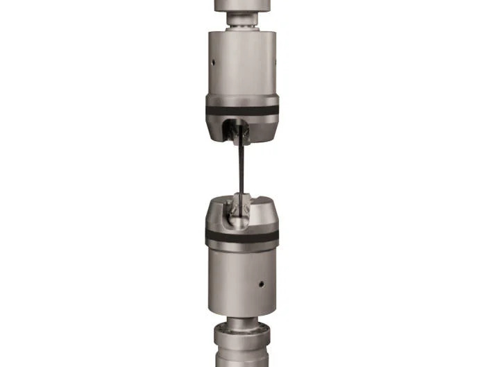
Principle of Operation
The bending force is applied as the specimen is forced against the plunger, either as the base is raised with the table or as the crosshead moves down depending on the frame being used. The plunger forces the specimen into a 180 degree bend against the rollers on the base.
On the weld bend test fixture, one half of the base can be adjusted to one of four different positions to allow for testing different thickness specimens. A separate plunger or strut is required for each thickness specimen, several struts are available depending on the fixture.
Guided bend fixtures have a fixed span base and a single diameter loading strut or plunger to form a complete assembly. Specimen loading is carried the same as with the weld bend fixture though a separate assembly must be purchased for each specimen thickness.
Application Range
- Type of Loading: compression bend
- Specimen Material: wrought or cast steel, non-ferrous materials
- Specimen Types: flat, flat welded
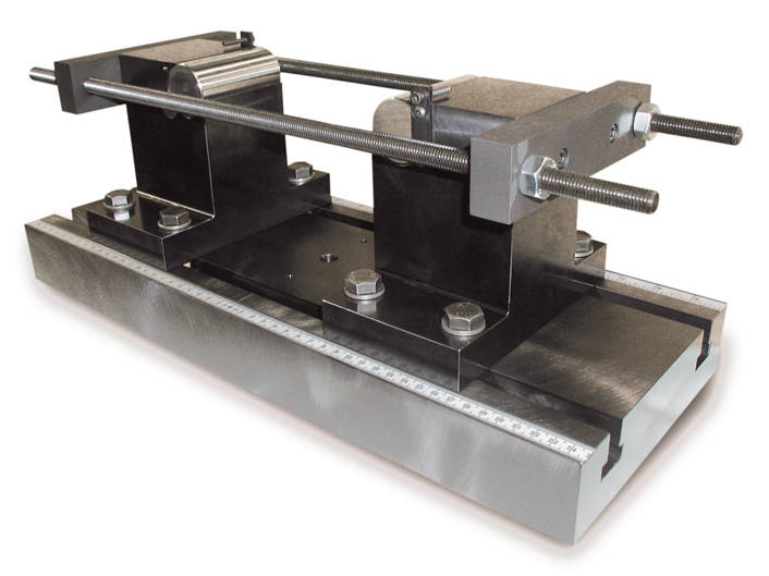
W-6810 | Guided-Bend/Weld Bend Test Fixture
Guided-Bend / Weld Bend Test Fixture, Adjustable Span for "U" bend tests of plane plate or welded flat specimens.
Fixture consists of a t-slot base with adjustable span supports supported by two tie rods.
Fixture specifications:
- Span - 0 to 254 mm (10.0 in)
- Specimen width - up to 76 mm (3.0 in)
- Support diameter - 38.1 mm (1.5 in) roller
- Support depth - 135 mm (5.3 in)
- Maximum Capacity - 100 kN (22,500 lbf)
- Fixture Capacity
100kN (22,500 lbf) if installed fully supported
If installed with overhang, capacity is rated per below
Capacity = 100kN (22,500 lbf) where x < 125mm (5 in)
Capacity (kN) = 12,600/x when x > 125 mm
Capacity (lbf) = 111,900/x when x > 5 in
Where x = distance from end of machine loading table
to lower flexure support
- Lower connection - 12.7 mm (0.5 in) centering pin
- Weight: 59 kg (130 lb) not including loading noses
- Effective height with loading nose - 357 mm (14.06 in)
not including specimen thickness.
Fixture meets the following US and International standards:
ASTM A370-07a, ASTM E190-92, ASTM E290-97a, ANSI/AWS B4.0-98, API 1104, API 5L, AS 2205.3.1, ASME IX 2004, JIS Z2248, GOST 14019 (for specimens 19 to 38.1 mm thick), ISO 5173, ISO 7438, EN ISO 15630-1, EN 910.
Notes:
- Fixture requires loading noses (sold separately) of appropriate size for material being tested and standard being used.
- The bend fixture cannot bend the specimen to a complete 180 degrees due to necessary clearances between the loading nose and supports.
W-6810-A | US Customary Loading Nose Set for Guided/Weld Bend Test Fixture
Includes 0.5, 1.0, 1.5, 2.0 inch diameter loading noses.
- Loading nose width: 51 mm (2 in)
- Loading nose height: 171 mm (6.75 in)
- Attachment: Type R1m (1.0 in holding button)
CAUTION:
Most standards require loading nose diameters of 4 x specimen thickness. However, some standards allow for other diameter loading noses to be specified locally or as agreed between vendor and customer. It is the customer's responsibility to ensure the proper size loading noses are ordered.
Note: Other size loading noses available individually or in sets as special order.
W-6810-B | Loading Nose Set for Guided-Bend/Weld-Bend Test Fixture
Metric Loading Nose Set for Guided Bend / Weld Bend Test Fixture. Includes 12, 16, 20, 24, 32, 40, 48 mm diameter loading noses.
- Loading nose width: 51 mm (2 in)
- Loading nose length: 171 mm (6.75 in)
- Attachment: Type R1m (1.0 in holding button)
CAUTION:
Most standards require loading nose diameters of 4 x specimen thickness. However, some standards allow for other diameter loading noses to be specified locally or as agreed between vendor and customer. It is the customer's responsibility to ensure the proper size loading noses are ordered.
Note: Other size loading noses available individually or in sets as special order.
| Anvil Diameter | 38.1 mm (1.5 in) |
| Capacity | 100 kN (22,500 lbf) |
| Lower Fitting | 12.7 mm (0.5 in) ( ) |
| Specimen Width | up to 76 mm (up to 3.0 in) |
| Support Span | 0-250 mm (0-10 in) |
| Upper Fitting | Refer to W-6810-A/-B ( ) |