How to Connect Transducers to Instron Systems: Four Methods
Instron users can integrate third-party sensors and transducers into their test systems — for example, strain, temperature, pressure, displacement, or electrical resistance. The four most effective methods for connecting sensors and transducers to Instron testing systems are:
- Analog (0–10 volts) signals
- Rationalized connection (recommended)
- Custom polynomial calibration
- Raw and digital data via third-party equipment
Analog (0–10 volts) Input Method
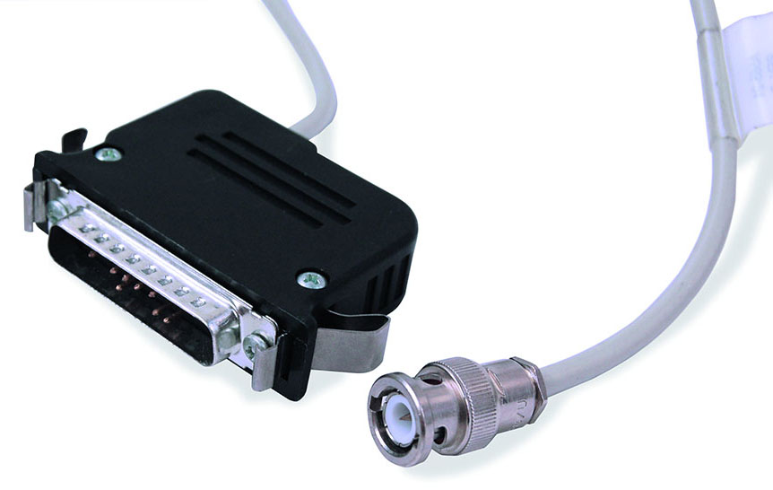
Analog signals may be the simplest and can be directly connected to any 25-pin sensor conditioning module (SCM) using the 2210-877 BNC to 25-pin adapter cable. Most devices with analog outputs use a BNC coaxial twist-lock connection and are externally powered or conditioned.
Rationalization Method (Most Direct and Recommended)
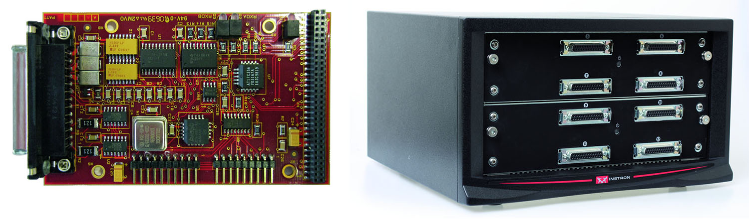
Instron can install a 25-pin connector with a Cal & ID board on the transducer to connect to any SCM. This allows it to easily connect to the controller and provides self-identification and automatic calibration from the Bluehill® Universal software. Power for the transducer is provided from the frame 25-pin connection and is typically low-voltage (mV) AC current.
Self-identification tells the software the type (force, strain, pressure, etc.) and capacity of the transducer. This allows for easy test method setup and over-limit protection.
Auto-calibration allows for a software calibration and linearization of the transducer. This calibrates the transducer to the controller electronics to provide an accurate measurement during testing.
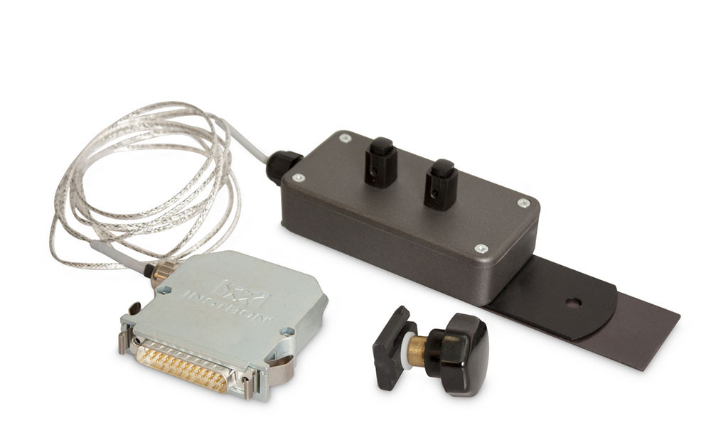
Strain gauges require external bridge completion. For single strain gauges (quarter-bridge), typically bonded to a composite specimen, Instron 2210-891/892 bridge completion adapters provide a quick-connection for the bonded gauge and a rationalized 25-pin connector to the frame.
Custom adapters are available to complete half-bridge configurations, as well as an adapter for full-bridge, which is primarily a convenient means of quick-connection for the strain gauge since no bridge completion is needed, and it provides a rationalized connection to the frame.
Note: The rationalization service needs to be done at the Instron factory in Norwood, MA (USA).
Custom Polynomial Calibration of a Transducer Method
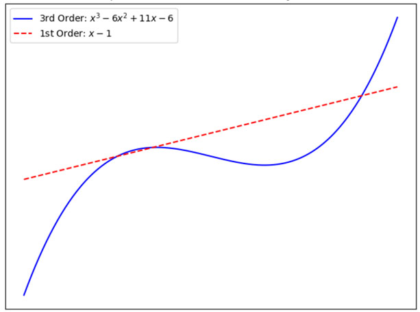
Custom Bluehill Universal (CP139390) is available for third order polynomial calibration of a single transducer. The standard calibration linearizes the transducer between two points (first order), zero and full-scale (clip-on extensometers), or zero and half-scale (load cells). A polynomial is used in many industries to improve the linearity of transducers.
Instron load cells are specifically designed for materials testing, mounted on frames, in mostly ideal environments. This feature is for customers using Instron equipment to test non-Instron load cells, with the Instron load cell being the “known-good” measurement. The user enters the three coefficients in the transducer dialog window for the software to use when creating the calibration file.
The plot illustration shows examples of first and third order polynomials.
External Digital Data Input Method
External raw data and digital data both require the third-party equipment source to import into Bluehill. Digital data is represented as discrete values. The controller converts analog inputs into digital data to be read into the software and saved on a computer. Focusing on transducers used in materials testing, the most common would be an encoder for measuring linear or rotational displacement.
Other examples include sensors for temperature, pressure, acceleration, light, humidity, etc. The challenge is that in this case for digital data, we are not referring to digital pulses, where each pulse equals some increment of the measurement. We want to report the actual value to the software and not count pulses.
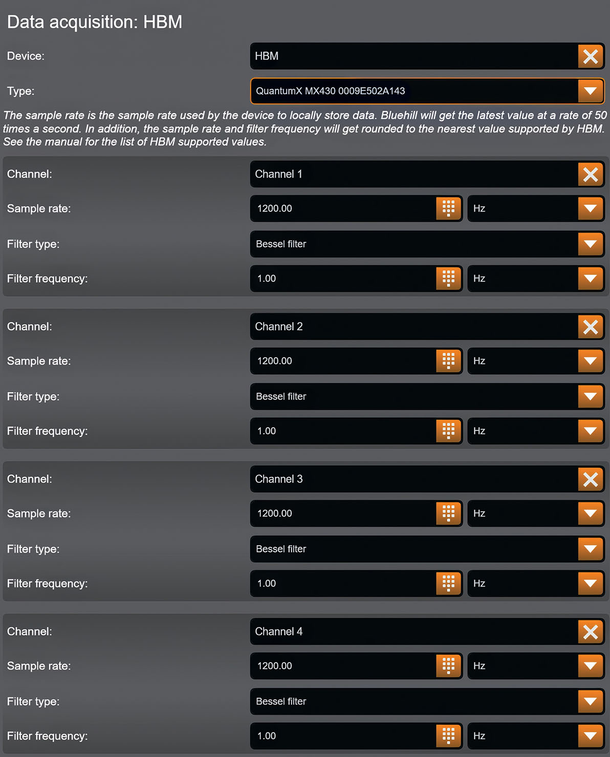
As part of the load cell manufacturing process, Instron uses HBM’s QuantumX MX430B, a four-channel measurement amplifier, which communicates directly with Bluehill Universal through the computer’s USB COM port. This QuantumX integration with Bluehill Universal is available as custom (CP136632). The HBM’s four channels are configured in Bluehill as Named Transducers, with options for sample rate and filtering type and frequency, including “No Filter,” thus providing raw data. There are other devices in the QuantumX family that can accept digital data.
What Is Digital Data for Instron systems?
- Digital data refers to discrete numerical values that represent physical measurements (e.g., force, displacement, temperature).
- It is not just a stream of digital pulses (e.g., from a quadrature encoder), but rather actual measurement values communicated digitally.
- Digital data is typically converted from analog signals by the controller.
Why Digital Data Matters
- Precision: Digital data avoids analog signal degradation.
- Integration: Enables use of advanced sensors (e.g., encoders, temperature sensors).
- Flexibility: Supports non-Instron transducers in custom setups.
Note on External Raw Data
Raw data is uncalibrated, since the action of calibrating would linearize it, and converting from an analog to digital signal would inherently result in some filtering, thus it would no longer be “raw data.” All data that is brought in through the Instron’s Controller must be calibrated.
Summary of Methods to Connect Transducers to Instron Systems
Analog (0–10 V) Signals
- Simple and direct
- Requires a BNC to 25-pin adapter
- External power supply needed
Rationalized Connection (Recommended)
- Uses a 25-pin connector with a Cal & ID board
- Enables self-identification and auto-calibration in Bluehill Universal
- Supports strain gauges with bridge completion adapters
Custom Polynomial Calibration
- Primarily used for non-Instron force transducers
- Supports third-order polynomial calibration for improved accuracy
- Useful when comparing to a “known-good” Instron load cell
Raw and Digital Data via Third-Party Equipment
- Requires devices like the HBM QuantumX MX430B
- Currently requires a custom version of Bluehill Universal
- Supports raw data through configurable filtering and sample rates
Instron’s ecosystem of adapters, software, and calibration options is built for flexibility. Whether you are working with non-Instron extensometers, load cells, or environmental sensors, there is a solution that fits your needs.
Do you have unique sensors or lab data workflows? Let us know — we will help you unlock even more value from your testing equipment.