Instron

Intervertebral Disc Testing

Biomedical Testing » Orthopedics

Intervertebral Disc Testing

The Challenge

Intervertebral Disc

Intervertebral disc replacement is a surgical technique for the treatment of lower back pain related to degenerative disc disease. The advantage of this technique over traditional spinal fusion is that it preserves or restores motion in the spine, and has the potential to delay the onset of degeneration of healthy discs at adjacent levels in the spine. Disc prostheses are designed to be load bearing over the physiological range of disc motion, and to give years of pain-free and trouble-free operation in the body. Understanding the static and dynamic characteristics of a particular device allows manufacturers and designers to ensure their product is proven and accepted. ASTM F2346 provides a methodology for characterizing the static strength and dynamic fatigue behavior of disc prostheses. The rigorous testing regimes in this standard aim to scientifically validate any prosthesis design. With a typical test run lasting for 10 million cycles and requiring both axial and torsional loading, it is vital that a testing system copes with these performance demands and delivers the highest quality of results. In addition, the requirement to conduct these tests in a wet environment adds to the complexity of the system.

Our Solution 

Intervertebral Disc Testing

An 8874 axial-torsional system, with the addition of a temperature controller and re-circulator unit, allows device manufacturers and contract research laboratories to conduct both static and cyclic testing on a range of implant designs. The bath, in which saline flow and temperature are controlled, provides a stable environment. With the use of specialized test fixtures, the 8874 system's combined axial-torsional actuator allows for characterization to be conducted in axial compression, compression-shear, and compression-torsion test modes for both articulating discs of traditional metal-on-metal or metal-on-polyethylene design. It's also used for the next generation of prostheses, which feature an elastomeric component to give axial compliance under load that mimic the biomechanics of the natural disc.

Knee Testing

Biomedical Testing » Orthopedics

Knee Testing

The Challenge

Knee Joint

Knee replacements are among the top surgical procedures worldwide for improving quality of life. Fatigue fracture of knee tibial trays is one of the most commonly reported failure mechanisms of total knee replacements (TKR). It is caused by the loss of underlying bone support resulting from biological reactions, such as wear-induced osteolysis. Under these conditions, the tibial tray becomes mechanically unstable, and cyclic loading imparted by normal walking causes fatigue cracks, ultimately leading to catastrophic failure.

Our Solution 

Knee Joint Testing

The ElectroPuls™ All-Electric Dynamic Test Instrument assists designers, manufacturers, and researchers through the product life-cycle process, from deriving fundamental material properties, such as resistance to fatigue crack propagation, to testing the entire tibial tray and beyond. We use a clamping fixture to secure one half of the tibial tray, simulating a fully supported condyle. The other unsupported condyle is then subjected to physiologically representative loading. By using our unique Dynacell™ load cell, dynamic inertial errors, such as those caused by the fixturing and from hydro-dynamics that result when testing in an environmental bath, can be removed. This allows for a more accurate measurement of load being applied to the specimen.

Hip Implant Testing

Biomedical Testing » Orthopedics

Hip Implant Testing

The Challenge

Hip Implant

Following surgery, proximal loosening and stress shielding can occur as a result of normal activity and can lead to abnormal loading profiles. Therefore, the real-life environment and loads that the specimen will experience while in the body need to be replicated in testing. Hip femoral fatigue testing can be challenging due to the importance of precisely embedding the specimen. The fixture needs to be capable of supporting compression, bending, and torsional stresses in order to meet ISO 7206 standards. The high-frequency rates of these tests also pose a challenge as they can cause the specimen to heat up beyond an acceptable limit.

Our Solution

Hip Implant Testing

Instron® provides a specimen embedding device that ensures the required offset angles and embedding depth is achieved. The purpose-built corrosion resistant fixture allows for in vivo testing. The assembly comes complete with a temperature controller and a recirculating pump to ensure the temperature never exceeds the acceptable limit by automatically reducing the frequency of the test. The easy-to-install fixture includes a low-friction loading head and adapters for mounting it to an ElectroPuls™ system. The Instron WaveMatrix™ software allows a number of test-end criteria to be used, such as running a specific number of cycles or until specimen fail is detected, which can be determined in a number of ways. With one package you can confidently test to and exceed the requirements for ISO 7206-4, 7206-6, and 7206-8.

Bone Screw Testing

Biomedical Testing » Orthopedics

Bone Screw Testing

The  Challenge

Bone Screw

Bone screws are used in surgical procedures for securing implants, osteosynthesis devices, and fracture fixation plates to the skeletal system. In normal clinical use, a surgeon applies combined axial and torsional forces to the bone screw as it is implanted within the body. Manufacturers and scientists test bone screws to determine various mechanical properties when evaluating new materials and designs. The most common standard for testing bone screws is ASTM F534. The standard consists of a total of four testing annexes: axial tests, torsion only tests, or a combination of both linear and torsion tests. ASTM F543-17 Test A1 - Test Method for Determining the Torsional Properties of Metallic Bone Screws requires the screw to be sufficiently clamped and a rotational velocity between 1 and 5 rpm to be applied until specimen failure, and to measure the torque profile and the rotational angle. ASTM F534-17 Test A2 - Test Method for Driving Torque of Medical Bone Screws measures the torque required to insert and remove the screw with a constant rotational velocity between 1 and 5 rpm while maintaining an axial load of no more than 10 N in compression. ASTM F543-17 Test A3 - Test Method for Determining the Axial Pull-Out Strength of Medical Bone Screws measures the force required to axially remove the screw that has been fully inserted in the test block using the method from Test A2. The pull-out fixture then applies a tensile load at a constant rate of 5 mm/min until the failure of the bone screw or removal from the test block. ASTM F543-17 Test A4 - Test Method for Determining the Self-Tapping Performance of Self-Tapping Medical Bone Screws specifies the procedure to evaluate the axial loading required to engage a self-tapping bone screw into a standard laboratory material. Although considered a simple clinical procedure, reproduction of this in vitro results in a relatively complex motion due to the interaction between the rotation and linear axes of a test machine. The test requires a continuous rotational velocity of up to 30 rpm while the axial load is incremented during the insertion at a rate of 2 N/s. The objective of this test is to record the torque profile as the bone screw is inserted into the material and then removed.

Our Solution 

Bone Screw Testing

To perform bone screw testing to ASTM F543, either an electromechanical system with a Torsion Add-On 3.0 , or an ElectroPuls™ Linear-Torsion system can be used. The Torsion Add-On 3.0 can be added to any new or existing 6800 Series single column or dual column table top testing machine to add rotational capabilities. The ElectroPuls E10000 and E3000 Linear-Torsion test systems are all-electric dynamic testing systems that provide a unique linear and torsion actuator system that is capable of synchronized linear and multi-rotation testing, which makes them ideal platforms for performing the full range of tests prescribed by the standard. For both the electromechanical system and ElectroPuls system, a bi-axial Dynacell load cell is mounted to the base of the machine. Using WaveMatrix™ dynamic test software on the ElectroPuls system, a user is able to control both axial and rotational axis in closed-loop control. This gives the user the ability to easily set up the multi-axial tests as a series of steps, and displays the required information as the test proceeds. Special fixtures are used to clamp the material to the biaxial load cell, and a drill chuck is used for the drive bits.

Fracture Fixation Device Testing

Biomedical Testing » Orthopedics

Fracture Fixation Device Testing

The Challenge

Fracture Fixation

Fracture fixation plates are used to immobilize bones that have been fractured or severely broken. These plates are most commonly made from titanium or stainless steel. Both have similar mechanical properties, including stiffness and ultimate tensile strength, as native bone. These plates are often irregular geometries and come in a variety of sizes to accommodate different size bone fractures in the body. For example, a plate used to immobilize a fractured bone in a femur will be very different than one used in an ankle, finger, or jaw. The irregular geometry and size range of fracture fixation plates makes them challenging components to test. In addition, in most cases, these plates remain within a patient for life and must be able to withstand the dynamic motion of the body over decades of time.

Our Solution 

Fracture Fixation Device Testing

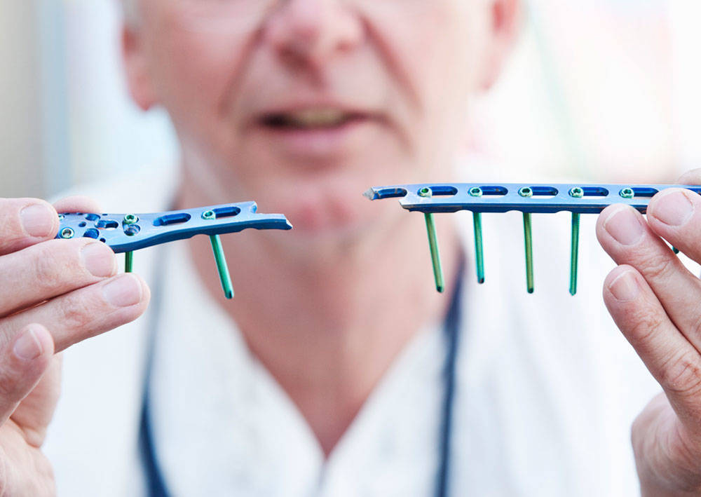
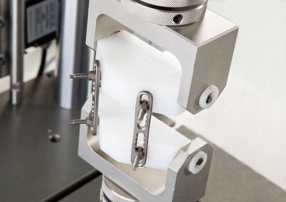
In order to understand the mechanical properties of fracture fixation plates, a range of both static and dynamic tests are required. Monotonic flexural, tension, and compression testing is necessary to understand modulus and ultimate tensile strength. Given the irregular geometry of fracture fixation plates, measuring strain is a challenge. 2D and 3D modeling techniques, such as finite element analysis, are often conducted to understand full-field stress and strain properties of fracture fixation plates. For monotonic tensile, compression, or flexural testing, our Digital Image Correlation software paired with our Advanced Video Extensometer allows researchers and scientists to visualize and quantify the full-field strain properties of these plates. For all fatigue tests, we recommend using our ElectroPuls™ systems. Specifically, we recommend either the E3000 or E10000 Linear-Torsion test system. The ability to test plates simultaneously in axial loading and torsional loading best represents realistic loading conditions in the human body.

Spinal Implant Testing

Biomedical Testing » Orthopedics

Spinal Implant Testing

The Challenge

Spinal Implant Testing

Service life testing of spinal constructs is critical as fatigue failure is more common than catastrophic failure. During normal patient activity, spinal constructs can be subjected to high in vivo loading, which may result in catastrophic failure. Cyclic testing is performed in order to evaluate the number of cycles it takes for fatigue failure to occur. Loading is typically applied with a constant-amplitude load-controlled sinusoidal waveform running in excess of five million cycles. Simple static testing is also performed to evaluate the load required to result in spinal fracture.

Our Solution

Spinal Implant Testing

The Instron® Linear-Torsion ElectroPuls™ system is recommended as it allows the user to complete both static and dynamic tests according to ASTM F1717-12 standards on a single machine. A dedicated spinal fixture can easily be mounted to this system with the option of mounting a saline bath onto the base for in vivo testing. When using the bath, the load cell is designed to be mounted onto the actuator utilizing Instron’s patented Dynacell technology for inertia compensation. Instron’s patented stiffness-based turning algorithm ensures excellent waveform fidelity, even with non-linear specimens.