ASTM A615 Testing of Steel Reinforcing Bars
A Guide to ASTM A615 Standard Specification for Deformed and Plain Carbon-Steel Bars for Concrete Reinforcement

Updated: January 28, 2026
What is ASTM A615?
ASTM A615 is a testing standard that defines the dimensional, chemical, and physical requirements for plain and deformed carbon-steel reinforcing bars used in concrete construction. It establishes material grades and performance criteria to ensure reinforcing steel delivers consistent strength, ductility, and reliability in structural applications.
Steel reinforcing bars (rebar) manufactured in accordance with ASTM A615 are designed to absorb the stress and weight of concrete structures, including bridges, buildings, and other infrastructure.
Rebar may be supplied in cut lengths or coils, depending on the application. Deformed reinforcing bars feature patterned surface protrusions that enhance mechanical bonding and prevent longitudinal movement once embedded in concrete, while plain bars have smooth surfaces and are typically used where anchorage demands differ.
Mechanical testing is performed to evaluate physical properties such as tensile strength, elongations, and satisfactory surface condition after bending. The standard references ASTM A370 for tensile testing procedures and ASTM E290 for bend testing.
Rebar produced in accordance with ASTM A706/A706M is also considered compliant with the requirements of ASTM A615.
Recommended System Configuration for Testing to ASTM A615
- 2580 Series load cell with a load measurement accuracy of ± 0.5% of reading down to 1/1000th of load cell capacity
- Advanced Hydraulic Wedge Action Grips, a robust tensile grip built to withstand high shock forces of rebar failures
- Floor model 6800 Series Universal Testing System rated up to 300 kN
- Bluehill Universal® software — includes a pre-built test method for ASTM A615

Key Considerations for ASTM A615 Tensile Testing
Gripping Rebar Specimens
ASTM A615 tensile testing commonly involves high shock forces at specimen failure, especially when testing larger bar diameters or higher-grade materials. Because grips retain the fractured bar halves after failure, they must be capable of safely absorbing this energy without risk of damage or loosening. Hydraulically actuated wedge or side‑acting grips are recommended for this application.


The standard specifies that specimens must be straightened prior to testing, especially when sourced from coils. Because it is common for these specimens to retain some bend, we recommend hydraulic side acting grips, such as Instron’s DuraSync grips. These grips clamp from both sides and maintain consistent centering even when side loads are present, which occurs when the specimen is bent — improving alignment and eliminating the need to ‘reset’ the grips between tests.

Optimal Tensile Grip Jaw Faces for Rebar
Because ASTM A615 tensile specimens are tested using their full cross‑section, the surface deformations on rebar can complicate gripping. Rebar‑specific jaw faces feature optimized tooth geometries designed to prevent slippage without introducing localized stress concentrations that could cause premature failure.
Strain Measurement
ASTM A615 requires elongation to be reported for every tensile test. While elongation can be measured without an extensometer, there are many benefits of using one.
Automatic contacting extensometers, such as the Instron AutoX750, allow for measuring elongation of an 8-inch gauge length and can also calculate offset yield (Rp 0.2). Because the extensometer automatically attaches and removes itself during the test, the operator remains safely outside the test space during specimen failure.

Testing Tip: Gauge length is set automatically from inputs in Bluehill Universal and can be adjusted as needed over the entire travel of the AutoX750, making it suitable for not only ASTM A615 testing but also for other applicable tensile testing standards.
Test Control Methods
The test control method used for tensile testing of ASTM A615 material should be in accordance with ASTM A370, which permits testing by stress rate control, strain rate control, or crosshead displacement control. An important consideration is deciding how to manage testing when the specimen does not exhibit a well-defined yield point, which is a common characteristic of ASTM A615 materials.
Conducting a valid test requires the testing system to be out of strain rate control throughout discontinuous yielding, with the recommended changeover occurring at the 0.2% offset.
Testing Tip: Instron’s Bluehill Universal testing software enables automatic programming of this changeover to improve throughput and prevent invalid tests.
ASTM A615 Tensile Testing Procedure
Testing to ASTM A615 includes 5 basic regions including pretest, preload, elastic region, yielding, and plastic region.
Pretest Setup
During pretest, it is important to verify that the appropriate grips are installed and opening adjustments are made. Prior to installing the specimen, the force (load) measurement should be set to zero. Once the specimen is clamped in the grips, the force reading should not undergo any further ‘zeroing’ as this will affect test results.
If a manual extensometer is used for strain measurement, attach it carefully at the specified gauge length and then zero the strain measurement prior to loading the specimen.
Preloading
A small preload — typically less than 5% of the expected yield strength — is applied to seat the specimen in the grips and pull the specimen straight prior to testing. A plot of stress or force versus crosshead or actuator displacement will typically show significant displacement for a minimal increase in load due to the grips and load string pulling tight (taking up system compliance).
If a preload is not applied and an extensometer is used, many rebar specimens will exhibit negative strain at the beginning of the test as the specimen straightens. Because of this and/or system compliance, the data during the preloading portion of the test is often ignored or not recorded on the stress-strain graph.


On servo-controlled systems, preloading is usually performed slowly using crosshead or actuator displacement feedback for controlling the test speed. Controlling preloading from load, stress, or strain feedback is not recommended as it could lead to rapid acceleration until the specimen is pulled tight in the grips.
Depending on the amount of system compliance or slack reduction during the preload, it may be necessary to zero strain measurement at the end of preloading. However, caution must be taken to avoid adversely affecting the overall strain measurement. In either case, test results that rely on strain from the extensometer should be adjusted so any non-linear behavior at the very beginning of the test curve does not adversely affect any test results.
Elastic Region
The elastic region or straight line portion of the stress-strain curve may initially exhibit some non-linear behavior due to additional straightening of the rebar. If using an extensometer, this may present as slightly negative strain at the start of the test and is generally considered normal for rebar.
When testing to ASTM A615, the latest edition of ASTM A370 should be referenced for proper test control and target speeds in the elastic region and until the onset of yielding.
When running the tests on servo-controlled systems, it is important to keep the following scenarios in mind:
- If using crosshead or actuator displacement control, it is generally acceptable to use the same control and speed through both the elastic and yielding portions of the test.
- However, if stress or strain feedback control is used, the test must switch to crosshead or actuator displacement control just prior to or at the onset of yielding.
Yielding
Many rebar grades exhibit a distinct yield point characterized by an abrupt bend in the strain-strain curve, followed by a period of elongation with little to no increase in force.
Because of this, servo-controlled systems must be controlled using crosshead or actuator displacement feedback to maintain a constant rate of travel throughout yielding.
It is very important to note that using stress control during yielding will cause the test to accelerate excessively, which is in direct violation of the standards. This can also cause the yield point (upper yield) to be masked or smoothed and cause yield strength results to be higher than expected.
Likewise, strain control from an extensometer can also become erratic during yielding and is therefore not recommended when testing rebar.


Plastic Region
After yielding is complete, ASTM A370, and thereby ASTM A615, permits an increase in test speed to reduce overall test duration.
For servo-controlled machines, the best way to control the test during this final region is from crosshead or actuator displacement feedback (same as yielding).
Testing Tip for ASTM A615
It is common in ASTM A615 testing to generate scale and dust on the equipment after each break. Instron 6800 Series floor model universal testing systems are engineered with enhanced ingress protection to protect internal componentry and electronics against dust and debris, allowing it to operate in the most demanding environments.
That said, it is still recommended that you brush away or vacuum scale between tests to maintain good engagement of the specimen between the jaw faces. Neglecting this good housekeeping practice could lead to specimen halves getting stuck in the jaw faces, which may require additional effort to dislodge.

Final Note
This guide provides an overview of key elements involved in an ASTM A615 test, however, it is not a substitute for the official ASTM A615 standard. Anyone planning to perform this test should consult the full standard for complete instructions and compliance requirements.

Additional Metals Testing Resources
Find insights into other metals applications in our Metals and Construction and Building Materials Testing knowledge bases.

6800 Series Premier Testing Systems Brochure
Instron 6800 Series Universal Testing Systems provide unparalleled accuracy and reliability. Built on a patent-pending Operator Protect system architecture with an all-new Smart-Close Air Kit and Collision Mitigation features, the 6800 Series makes materials testing simpler, smarter, and safer than ever before.

Bluehill Universal Brochure
Bluehill Universal is Instron’s advanced materials testing software, designed for intuitive touch interaction and streamlined workflows. It offers pre-loaded test methods, QuickTest for rapid setup, enhanced data exporting, and Instron Connect for direct service communication. Users of Bluehill 2 and Bluehill 3 can easily upgrade to the latest version for improved performance and usability

High Force Universal Testing Machines Brochure
Instron’s high force systems include electromechanical and high-capacity hydraulic testing systems for tension and compression applications. Force capacities range from 100 kN to 2000kN.
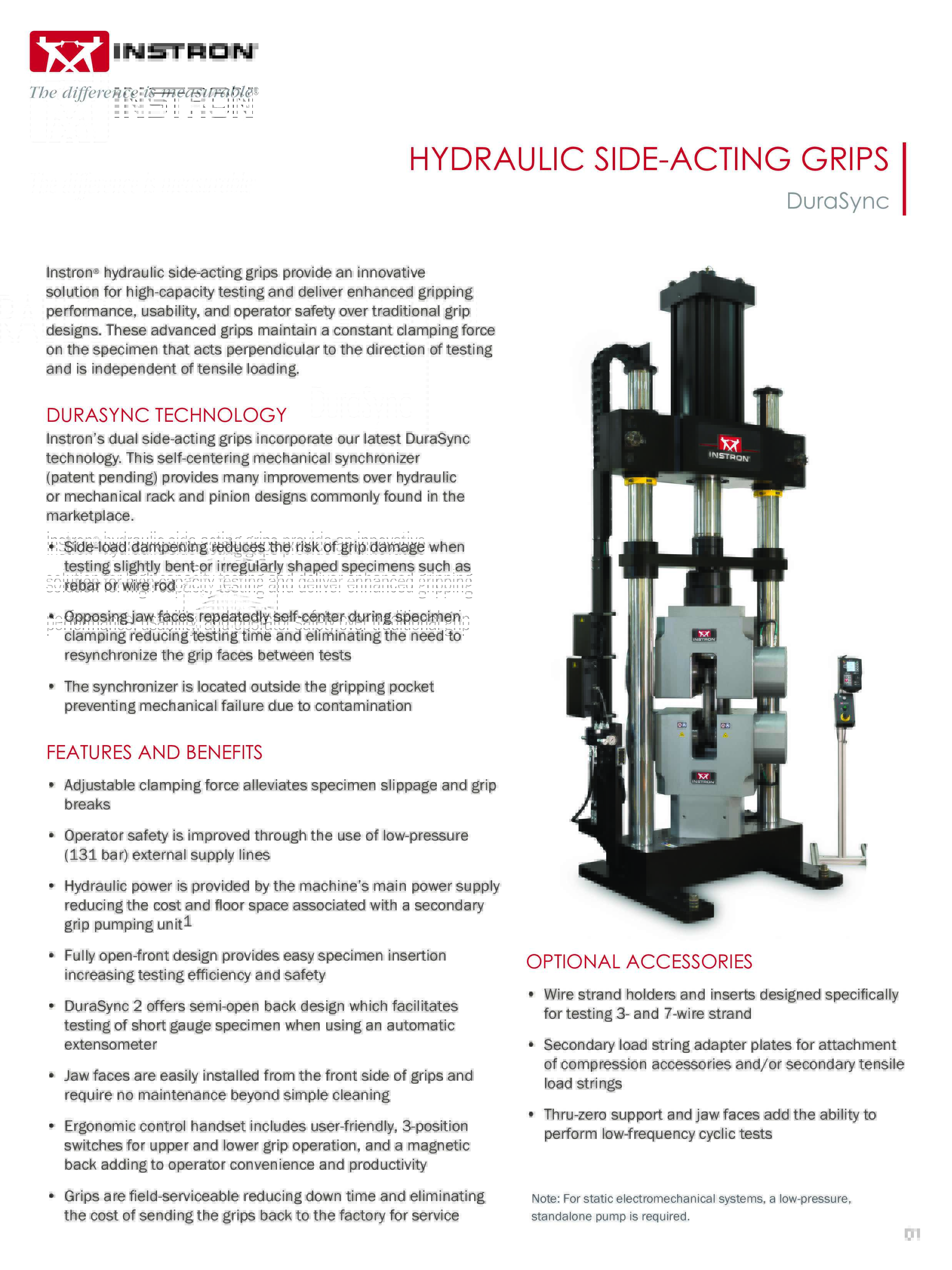
Hydraulic Side-Action Grips (DuraSync)
Instron hydraulic side-action grips are designed for high-capacity testing and maintain a constant clamping force on the specimen that acts perpendicular to the direction of testing and is independent of tensile loading.
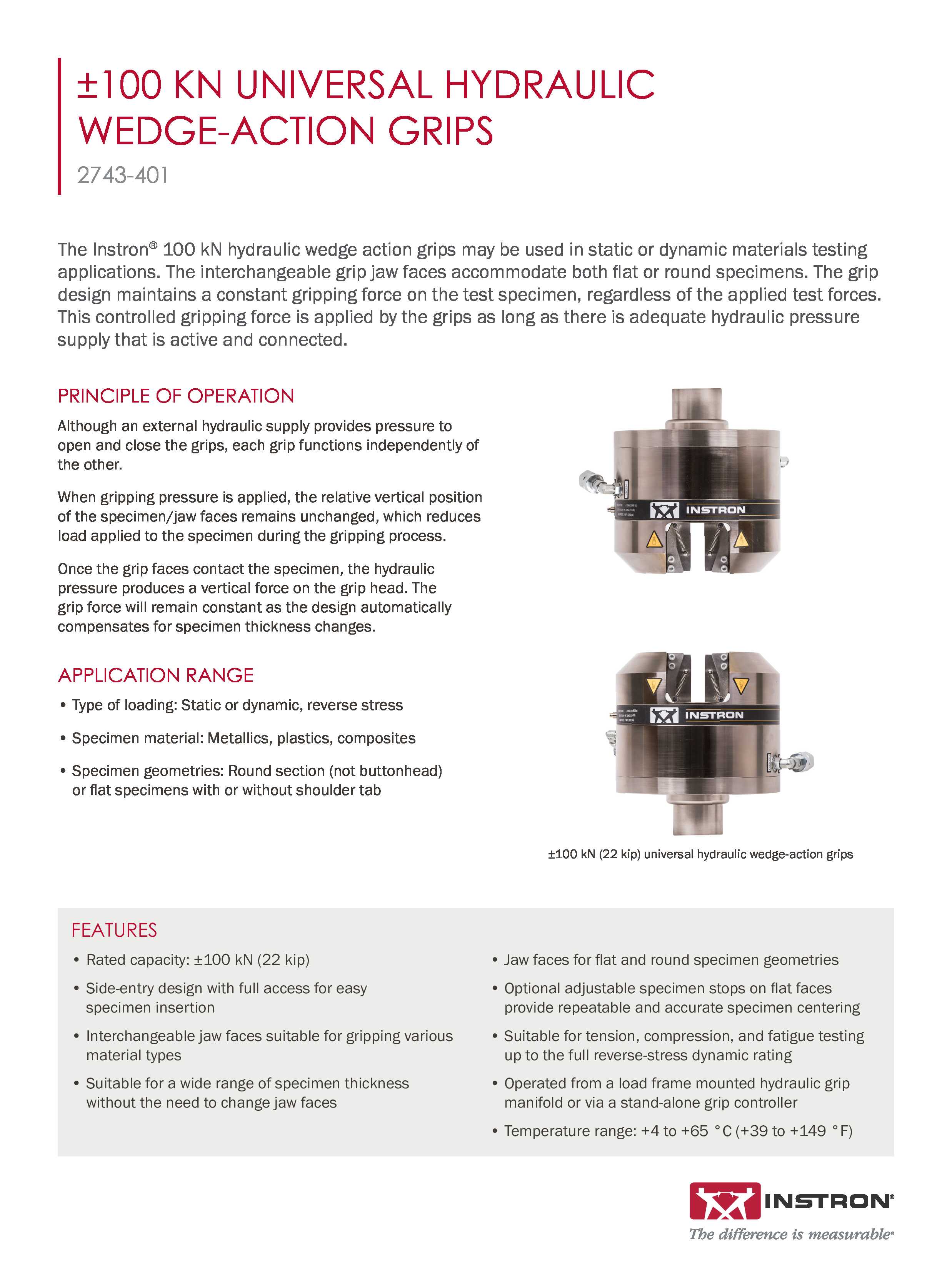
±100 kN Universal Hydraulic Wedge Action Grips Data Sheet
Instron’s 100 kN hydraulic wedge grips (catalog no. 2743-401) provide an innovative solution for high-capacity testing and deliver enhanced gripping performance, usability, and operator safety.
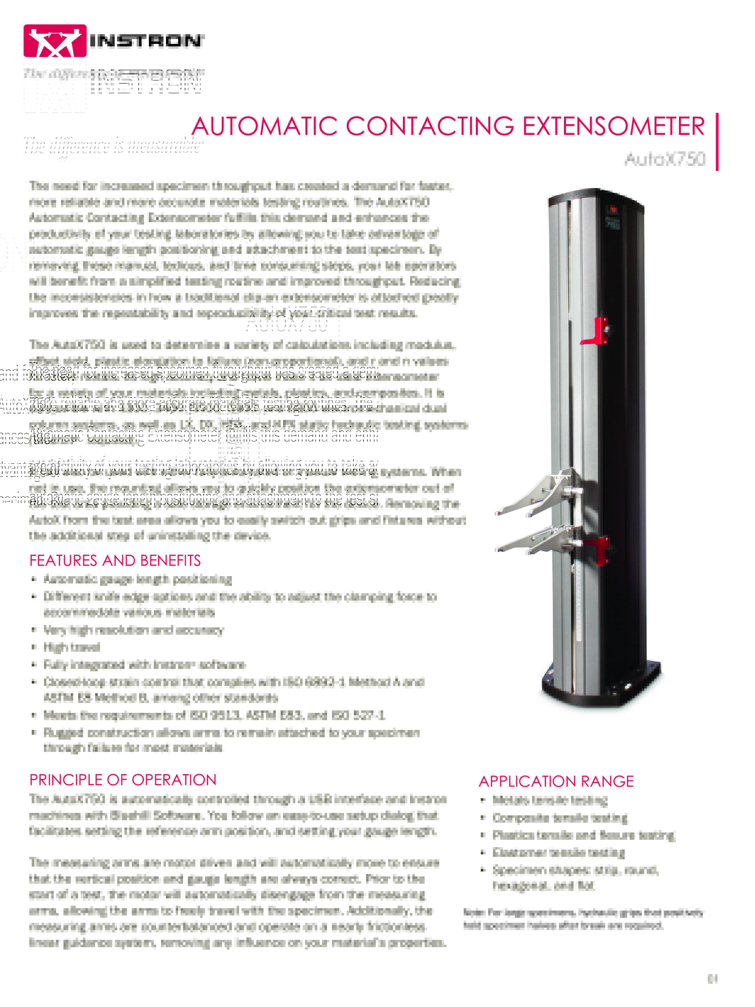
Automatic Contacting Extensometer – Model AutoX 750
The AutoX 750 is a high-resolution, long-travel automatic contacting extensometer. It can be mounted onto any electromechanical 3300, 3400, 5500, 5900, or 6800 Series tabletop or floor model system as well as LX, DX, HDX, and KPX static hydraulic testing systems. It is well suited for applications involving plastics, metals, biomedical, composites, elastomers, and more. The AutoX has a maximum travel of 750 mm and accuracy of ± 1 µm.