Supports, Tup Holders, and Inserts
How Interchangeable Supports, Tup Holders, and Inserts of a Drop Weight Impact Tester Work
Various sizes and capacities of the tups and inserts can be fitted and changed. These accessories are available for many applications, including puncture, compression after impact (CAI), tensile impact, and wedge peel testing.
Use the links below to jump directly to the section you are interested in:
Supports | Tup Holders | Tups and Inserts | Strain Gauge Tups and Inserts | Piezo Tups and Inserts
Puncture Impact Test Supports | Compression After Impact (CAI) Test Supports | Tensile Impact Test Supports
Wedge Peel Impact Test Supports | 3-Point Bending: Charpy and Izod Impact Test Supports | Pipe Testing
Supports
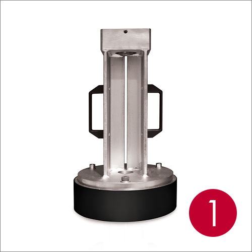
Test supports, a key component of the 9400 Series Drop Weight Testers, are designed to test a wide range of standards, components, and products. The support set includes a stand, where the specimen rests, and clamping mechanisms that push the specimen against the stand and hold it securely in place during an impact test.
Supports can be custom designed to test a wide variety of uniquely sized parts and components. Please ask about options for your application.

Tup Holders
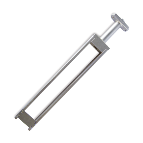
The tup holder joins the tup mechanically to the recovery/release system. One or more weights can be added to increase the impact mass. Tup holders come in three types: Light (for masses from 2 to 5 kg, tup included), Standard (for masses from 5 to 70 kg, tup included), or Reinforced (same as Standard, but used only with the 222 kN tup).
A range of tup holders and additional weight sets are available for the 9400 Series Drop Weight Testers, used to tailor energy requirements to your needs by reducing the minimum energy or adding to the maximum energy available.

| Code | Description | Weight Range | Energy Range | Velocity Range | Drop Tower | |
|---|---|---|---|---|---|---|
| Included with the machine | Standard Tup Holder | 0.5 - 3.00 kg 1.10 - 6.83 lbs |
0.15 - 21 J 0.11 - 15.49 ft-lbs |
0.77 - 3.7 m/s 2.53 - 12.14 ft/s |
9310 | |
| C-7510-022 C-7510-022REP |
Lightweight Tup Holder | 1.0 - 3.5 kg 2.20 - 7.72 lbs |
0.30 - 37.8 J 0.21 - 27.9 ft-lbs |
0.77 - 4.65 m/s 2.53 - 15.3 ft/s |
9440 | |
| C-7510-021 C-7510-021REP |
Standard Weight Tup Holder | 3.0 - 22.5 kg 6.61 - 49.6 lbs |
0.88 - 243 J 0.65 - 179 ft-lbs |
0.77 - 4.65 m/s 2.53 - 15.3 ft/s |
9440 | |
| C-7510-026 C-7510-026REP |
Additional Weight Set for Standard Weight Tup Holder | Up to 37.5 kg Up to 82.7 lbs |
Up to 405 J Up to 299 ft-lbs |
0.77 - 4.65 m/s 2.53 - 15.3 ft/s |
9440 | |
| CP117894* | Ultra Lightweight Tup Holder – used with CP131009 Ultra Light Tup; Piezo Sensor; 22 kN | 0.50 – 0.70 kg 1.10 – 1.54 lbs |
0.15 – 7.55 J 0.11 – 5.57 ft-lbs |
0.77 - 4.65 m/s 2.53 - 15.3 ft/s |
9440 | |
| CP117753* | Ultra Lightweight Tup Holder – used with CP131009 Ultra Light Tup; Piezo Sensor; 22 kN | 0.70 – 0.95 kg 1.54 – 2.09 lbs |
0.22 – 10.25 J 0.16 – 7.6 ft-lbs |
0.77 - 4.65 m/s 2.53 - 15.3 ft/s |
9440 | |
| C-7520-022 C-7520-022REP |
Lightweight Tup Holder | 2.0 - 5.0 kg 4.4 - 11.0 lbs |
0.59 - 54.0 J 0.44 - 39.8 ft-lbs With High Energy 0.59 – 931 J with 5.0 kg 0.44 – 687 ft-lbs with 11.0 lbs |
0.77 - 4.65 m/s 2.53 - 15.3 ft/s With High Energy 0.77 – 24 m/s with 2.0 kg 2.53 – 78.7 ft/s with 4.4 lbs |
9450 | |
| C-7520-021 C-7520-021REP |
Standard Weight Tup Holder | 5.0 - 30.5 kg 11.0 - 67.2 lbs |
1.47 - 329 J 1.08 - 243 ft-lbs With High Energy System: 1.47 – 1,426 J with 30.5 kg 1.08 – 1,052 ft-lbs with 67.2 lbs |
0.77 - 4.65 m/s 2.53 - 15.3 ft/s With High Energy System: 0.77 – 19.3 m/s with 5.0 kg 2.53 – 32.0 ft/s with 67.2 lbs |
9450 | |
| C-7520-026 C-7520-026REP |
Additional Weight Set for Standard and Reinforced Tup Holders | Up to 70.0 kg Up to 154 lbs |
Up to 757 J Up to 558 ft-lbs With High Energy System: Up to 1800 J Up to 1,328 ft-lbs |
0.77 - 4.65 m/s 2.53 - 15.3 ft/s With High Energy System: Up to 7.17 m/s Up to 23.5 ft/s |
9450 | |
| C-7520-027 C-7520-027REP |
Additional Weight Set for Wedge Peel Testing. To be used with C-7520-021 and C-7520-026 | Up to 45 kg Up to 99.2 lbs |
Up to 486 J Up to 358 ft-lbs With High Energy System: Up to 1585 J Up to 1,169 ft-lbs |
0.77 - 4.65 m/s 2.53 - 15.3 ft/s With High Energy System: Up to 8.4 m/s Up to 27.6 ft/s |
9450 | |
| C-7520-935 C-7520-935REP |
Reinforced Tup Holder for 222 kN (50,000 lb) Tup | 9.0 - 35.0 kg 20.0 - 77.0 lbs |
1.77 - 378 J 1.30 - 279 ft-lbs With High Energy System: Up to 1478 J Up to 1,090 ft-lbs |
0.77 - 4.65 m/s 2.53 - 15.3 ft/s With High Energy System: Up to 9.2 m/s Up to 30.3 ft/s |
9450 | |
| CP131572 | Ultra Lightweight Tup Holder w/22 kN Piezo Sensor Tup | 930 g 2.05 lbs |
0.29 – 10.79 J 0.21 – 7.95 ft-lbs With High Energy System: 0.29 – 98 J 0.21 – 72.28 ft-lbs |
0.77 – 4.65 m/s 2.53 – 15.3 ft/s With High Energy System: 0.77 – 14 m/s 2.53 – 45.9 ft/s |
9450 |
Tups and Inserts
The tup impacts the specimen surface when the impact test is carried out. This mechanical component comes in diverse shapes, sizes, and weights. Interchangeable inserts (the head of the tup) complete the tup configuration; their shapes can follow international standards or be custom designed. The required capacity depends on the application and is based on the expected maximum load, not the machine's energy capacity.
Instrumented tups are designed with either a strain gauge or piezoelectric sensor embedded in the tup insert. These devices capture the impact and transform it into an electric signal, which is collected by a data acquisition system so the user can see a picture of the impact.
Strain Gauge or Piezoelectric
Tups with a strain gauge sensor or piezoelectric sensor are chosen depending on the material type. Typically, strain gauge sensors are recommended for impact testing of materials made from composites, that fail in a ductile mode, and that are anticipated to have load values greater than 5 kN (1,124 lbs). Piezoelectric sensors are ideal when testing fairly brittle or light-load materials, such as thin films.
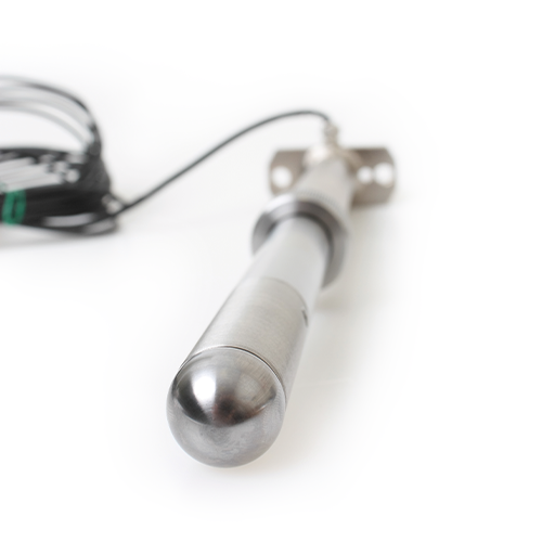
Strain Gauge Tups and Inserts
Strain Gauge Tups
| Code | Description | Maximum Force Capacity | Minimum Insert Diameter (For Puncturing Test) | Drop Tower |
|---|---|---|---|---|
| C-7519-301 | Strain Gauge Tups | 22 kN 5,000 lbs |
10 mm 0.394 in |
9440 |
| C-7519-302 | Strain Gauge Tups | 45 kN 10,000 lbs |
20 mm 0.787 in |
9440 |
| C-7519-303 | Strain Gauge Tups | 90 kN 20,000 lbs |
20 mm 0.787 in |
9440 |
| C-7529-301 | Strain Gauge Tups | 22 kN 5,000 lbs |
10 mm 0.394 in |
9450 |
| C-7529-302 | Strain Gauge Tups | 45 kN 10,000 lbs |
20 mm 0.787 in |
9450 |
| C-7529-303 | Strain Gauge Tups | 90 kN 20,000 lbs |
20 mm 0.787 in |
9450 |
| C-7529-304 | Strain Gauge Tups | 222 kN 50,000 lbs |
20 mm 0.787 in |
9450 |
Strain Gauge Tup Inserts
Piezo Tups and Inserts
Piezo Tups
| Code | Description | Maximum Force Capacity | Minimum Insert Diameter | Drop Tower |
|---|---|---|---|---|
| C-7519-794 | Piezo Tup | 4.5 kN 1,000 lbs |
12.7 mm 0.50 in |
9440 |
| C-7519-796 | Piezo Tup | 22 kN 5,000 lbs |
12.7 mm 0.50 in |
9440 |
| C-7519-701 | Piezo Tup | 0.45 kN 100 lbs |
20 mm 0.787 in |
9440 |
| C-7519-704 | Piezo Tup | 4.5 kN 1,000 lbs |
20 mm 0.787 in |
9440 |
| C-7519-706 | Piezo Tup | 22 kN 5,000 lbs |
20 mm 0.787 in |
9440 |
| C-7529-794 | Piezo Tup | 4.5 kN 1,000 lbs |
12.7 mm 0.50 in |
9450 |
| C-7529-796 | Piezo Tup | 22 kN 5,000 lbs |
12.7 mm 0.50 in |
9450 |
| C-7529-701 | Piezo Tup | 0.45 kN 100 lbs |
20 mm 0.787 in |
9450 |
| C-7529-704 | Piezo Tup | 4.5 kN 1,000 lbs |
20 mm 0.787 in |
9450 |
| C-7529-706 | Piezo Tup | 22 kN 5,000 lbs |
20 mm 0.787 in |
9450 |
Piezo Tup Inserts
| Code | Description | Testing Standard | Tup Compatibility | Adaptor** |
|---|---|---|---|---|
| C-7529-402 | 12.7 mm (1/2 in) Ø Hemispherical |
ASTM D3763, ASTM D7192, ASTM D5628, Method FD | C-7529-794 C-7519-794 C-7529-796 C-7519-796 |
N/A |
| C-7519-425 | 16 mm (5/8 in) Ø Hemispherical With CAI dedicated extender |
ASTM D7136/7136M, Airbus AITM 1.0010, PR-EN 6038, ISO 18352, Boeing BSS 7260, SACMA 2R-94 | C-7519-794 C-7519-796 |
N/A |
| C-7519-426 | 16 mm (5/8 in) Ø Hemispherical (For non-puncturing test) With CAI dedicated extender |
ASTM D7136/7136M, Airbus AITM 1.0010, PR-EN 6038, ISO 18352, Boeing BSS 7260, SACMA 2R-94 | All C-7519-7XX Piezo Tups | C-7529-494 |
| C-7529-404 | 20 mm (0.787 in) Ø Hemispherical |
ISO 6603-1, -2, ISO 7765-1, -2, ASTM D5628 Method FE | All C-7519-7XX and C-7529-7XX Piezo Tups | C-7529-494 |
| C-7529-430 | 50 mm Ø Flat Faced | - | All C-7519-7XX and C-7529-7XX Piezo Tups | C-7529-494 |
| C-7529-406 | 25.4 mm (1 in) Ø Hemispherical | - | All C-7519-7XX and C-7529-7XX Piezo Tups | C-7529-496 |
| C-7529-407 | 38.1 mm (1.5 in) Ø Hemispherical |
ASTM D5628 Method FC; ASTM D1709; ISO 7765-1 | All C-7519-7XX and C-7529-7XX Piezo Tups | C-7529-497 |
| C-7529-412* | Plastic Charpy Insert | ISO 179-2 | All C-7519-7XX and C-7529-7XX Piezo Tups | C-7529-494 |
| C-7529-410* | Plastics IZOD Insert | ISO 180, ASTM D256 | All C-7519-7XX and C-7529-7XX Piezo Tups | C-7529-494 |
| C-7529-421* | Metals Charpy Insert | ASTM E23; ISO 148 | All C-7519-7XX and C-7529-7XX Piezo Tups | C-7529-494 |
| C-7529-425 | 16 mm (5/8 in) Ø Hemispherical |
ASTM D7136/7136M, Airbus AITM 1.0010, PR-EN 6038, ISO 18352, Boeing BSS 7260, SACMA 2R-94 |
C-7529-794 C-7529-796 |
N/A |
| C-7529-426 | 16 mm (5/8 in) Ø Hemispherical (For non-puncturing test) |
ASTM D7136/7136M, Airbus AITM 1.0010, PR-EN 6038, ISO 18352, Boeing BSS 7260, SACMA 2R-94 | All C-7529-7XX Piezo Tups for 9450/9350 | C-7529-494 |
*Note: Tup/Insert Alignment Tool Required. C-7529-050 for 9450/9350; C-7519-050 for 9440/9340
**Note: Adaptor is required and not included

Instron® 9450 Tup Anti-Rebound System (option):
Stops the tup after impact to avoid a secondary impact on the specimen. This system only engages when the tup rebounds a minimum of 25 mm (1 inch) or higher.

Instron 9450 Tup Lubricating and Cleaning Device (option):
Used to lubricate the tup insert prior to testing. This small oil tank has a pneumatic cylinder with a sprayer to lubricate the insert, and a nozzle for a jet of compressed air to remove residual debris.
Puncture Impact Test Supports
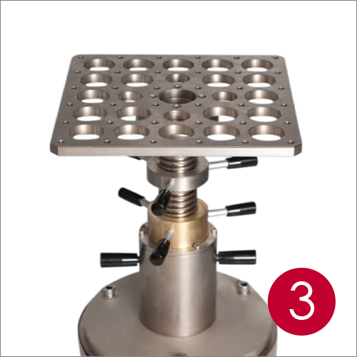
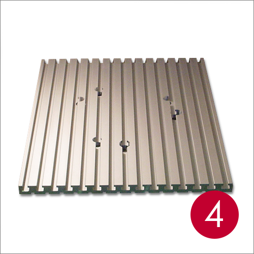
Clamping plates for the Instron 9440 and 9450 use a pneumatic system to push the sample against the test stand, holding it securely in place during the impact test.
Customized plates are available upon request.
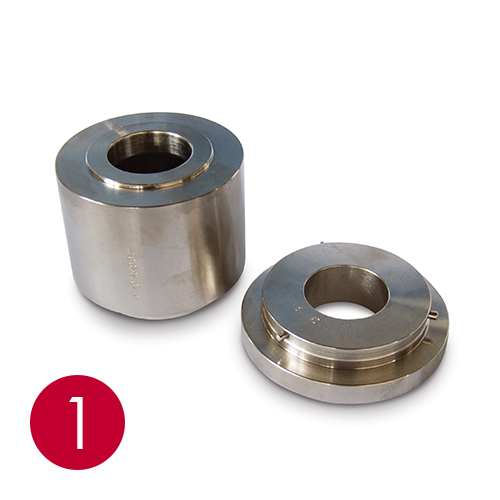
Puncture Test Accessories
Compression After Impact (CAI) Test Supports
Compression After Impact (CAI) testing is common for composite materials, to standards including Boeing BMS-7260, SACMA 2R-94, ASTM D7136/M, and Airbus AITM 1.0010. The fixture and insert vary for each test, and crosshead weight is very important. The anti-rebound system is required for all standards, while a tup and insert are required to complete the configuration and must be chosen based on the expected maximum load.
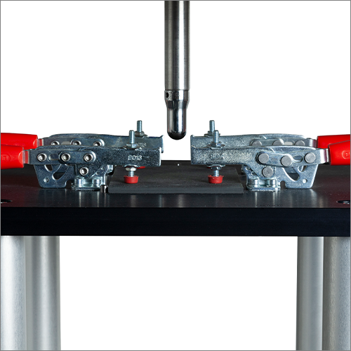
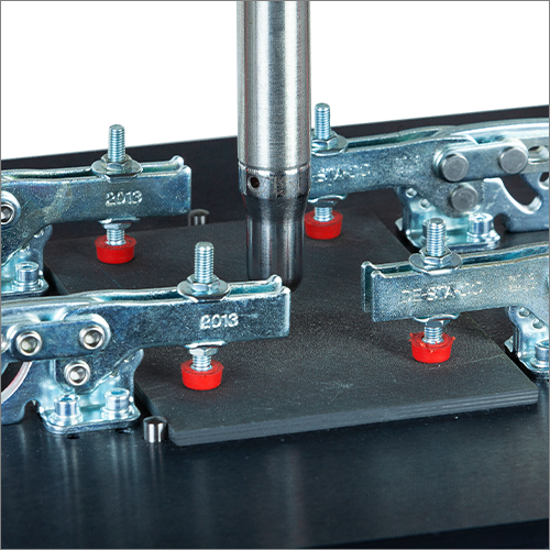
CAI Testing Accessories
Tensile Impact Test Supports
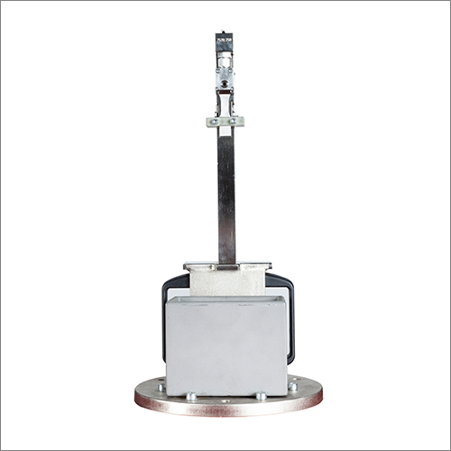
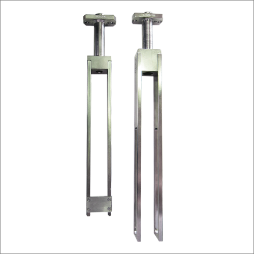
This instrumented vice is designed to meet ISO 8256 A for tensile impact tests. The fixture is suitable for specimen types 1–5 and equivalents, and includes fixed-height vice supports. The complete fixture requires selecting a piezoelectric force sensor, a clamping device, and a vice.
Tensile Impact Testing Accessories
Wedge Peel Impact Test Supports
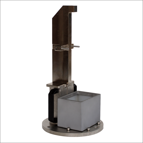
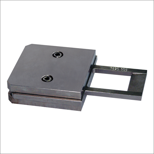
The wedge peel impact test (also known as the adhesive peel impact test) is an ISO test method used to measure the resistance of structural adhesives to cleavage fracture at various temperatures and test speeds of 2 and 3 m/s. This common test is used in both the development of new adhesives and the quality control of product batches.
Adhesive Peel Impact Testing Accessories
3-Point Bending: Charpy and Izod Impact Test Supports
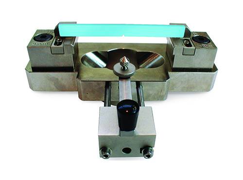
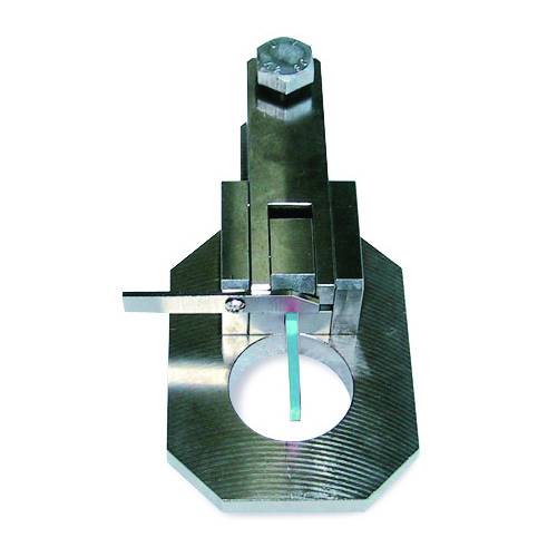
Fixtures are available for testing to ASTM D6110 (formerly ASTM D256), ISO 179, and ASTM E23 Charpy standards, and ASTM D256 and ISO 180 Izod standards. The tup is chosen based on the maximum load expected and is not related to the energy absorbed by the sample.
Charpy Testing Accessories
| Code | Description | Specimen Size | Span | Testing Standards | Drop Tower |
|---|---|---|---|---|---|
| C-7520-060 | Vice | - | - | ASTM D6110 (formerly ASTM D256), ISO 179, and ASTM E23 | 9440; 9340 9450; 9350 |
| C-7520-063 | Shoulders for Flatwise Specimen Positioning | 4 × 10 × 80 mm 1.57 in |
62 mm 2.44 in |
ISO 179 | 9440; 9340 9450; 9350 |
| C-7520-064 | Shoulders for Edgewise Specimen Positioning | 4 × 10 × 80 mm 1.57 in |
62 mm 2.44 in |
ISO 179 | 9440; 9340 9450; 9350 |
| C-7520-066* | Shoulders | 3.17 × 12.7 × 127 mm 0.125 × 0.50 × 5.00 in |
101.6 mm 4.00 in |
ASTM D6110 | 9440; 9340 9450; 9350 |
| C-7520-066* | Shoulders | 6.35 × 12.7 × 127 mm 0.25 × 0.50 × 5.00 in |
101.6 mm 4.00 in |
ASTM D6110 | 9440; 9340 9450; 9350 |
| C-7520-066* | Shoulders | 12.7 × 12.7 × 127 mm 0.50 × 0.50 × 5.00 in |
101.6 mm 4.00 in |
ASTM D6110 | 9440; 9340 9450; 9350 |
| C-7520-069 | Shoulders | 10 × 10 × 55 mm 0.39 × 0.39 × 2.17 in |
40 mm 1.57 in |
ASTM E23 | 9440; 9340 9450; 9350 |
| CP124590 | Anvil for 3-point bend test. Includes 2 sets of cylindrical shoulders. To be used with tup insert CP124589. | - | Adjustable from 40 mm up to 100 mm | - | 9440; 9340 9450; 9350 |
Izod Testing Accessories
Pipe Testing
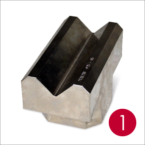
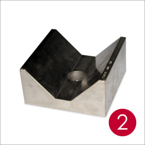
Our pipe testing fixtures feature a V-grooved design to hold cylindrical specimens up to 160 mm (6.30 in) and comply with ASTM D2444. A tup and insert are required to complete the configuration and must be chosen based on the expected maximum load.
Pipe Testing Accessories
| Code | Description | Specimen Size | Testing Standards | Drop Tower | |
|---|---|---|---|---|---|
| C-7520-210 | V-Groove Pipe Testing Fixture | 25.0 to 65.0 mm 0.98 to 2.56 in |
ASTM D2444 | 9440; 9450 9340; 9350 |
|
| C-7520-212 | V-Groove Pipe Testing Fixture | 80.0 to 160.0 mm 3.15 to 6.30 in |
ASTM D2444 | 9440; 9450 9340; 9350 |
|
| C-7520-215 | Flat Plate Pipe Testing Fixture | Small Pipes and Fittings | ASTM D2444 Type B | 9440; 9450 9340; 9350 |

Talk to an Instron Expert
Not sure which supports, tup holders, or inserts fit your 9400 Series testing application? Tell us about your requirements and we will help you find the right solution.
Talk to an Applications Engineer
Tell us about your testing needs, and we'll help you configure the right frame, load cell, grips, and software for your lab. Please complete the form below, and we'll respond within 1-2 business days. For a faster response, call +1-800-473-7838 or +1 781 828 2500 if you are outside of the US.

Resources
- 9400 Series Drop Weight Impact Testing System - Brochure
- 9400 Series Drop Weight Impact Testing System - Product Page
- Bluehill Impact for Drop Weight Impact Testing Systems
- 9400 Series Drop Weight Impact Testing System Low/High Temperature Chambers and Large Impact Areas
- Accessories for Materials Testing Catalog