Anvils

Anvils » Page 2

Anvils

Anvils are testing machine fixtures that hold specimens in-place during testing.  Many different styles are available to accommodate various test specifications and techniques.
Related Content

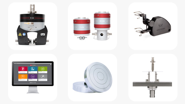
Testing Accessories

Find the right grip, sensor, fixture, or chamber for your testing needs — Instron's accessories are compatible with all Instron test systems.

3400 Series Universal Testing Systems Brochure

Instron 3400 Series universal testing systems for tensile, compression, bend, and other material property tests.
6800 Series Premier Testing Systems Brochure

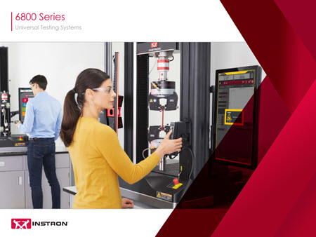
Instron 6800 Series Universal Testing Systems provide unparalleled accuracy and reliability. Built on a patent-pending Operator Protect system architecture with an all-new Smart-Close Air Kit and Collision Mitigation features, the 6800 Series makes materials testing simpler, smarter, and safer than ever before.
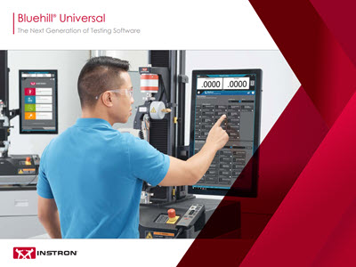
Bluehill Universal Brochure

Bluehill Universal is Instron’s advanced materials testing software, designed for intuitive touch interaction and streamlined workflows. It offers pre-loaded test methods, QuickTest for rapid setup, enhanced data exporting, and Instron Connect for direct service communication. Users of Bluehill 2 and Bluehill 3 can easily upgrade to the latest version for improved performance and usability.
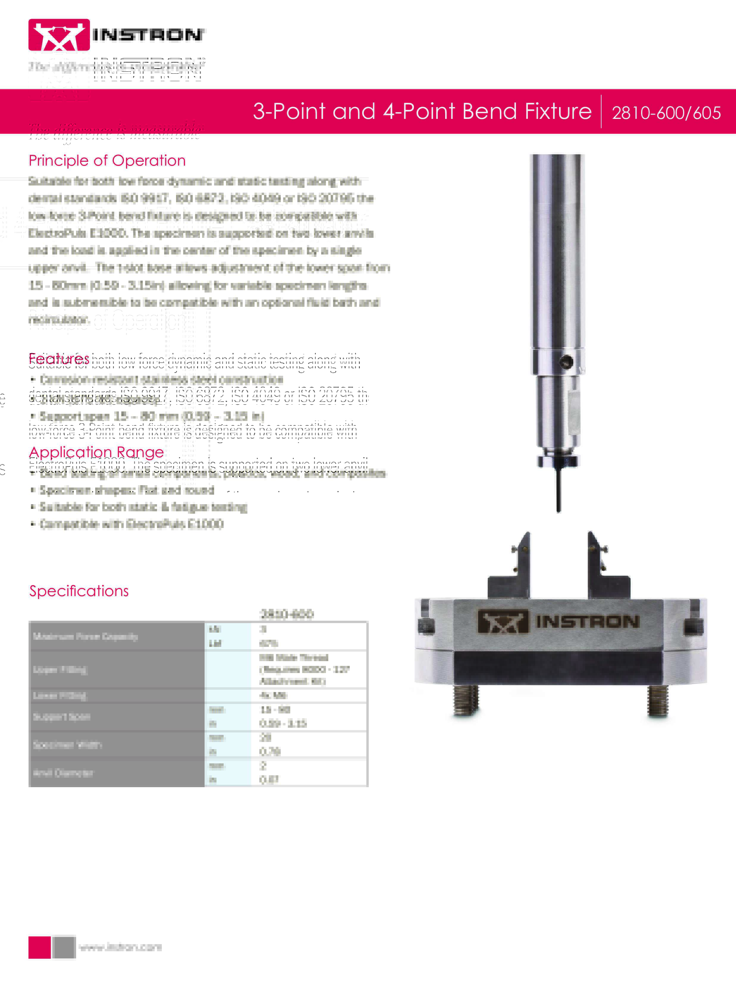
3 Point 4 Point Bend Fixture 2810-600

The 3-Point bend fixture is designed to easily provide the capability of a 3-point flexure test; it is suitable for both Dynamic & Static testing. The specimen is supported on two lower anvils and the load is applied in the centre of the specimen by a single upper anvil. The fixture has a variable span from 15 – 80 mm (0.59 – 3.15 in).
Anisotropic or Anisotropy

Anisotropic or Anisotropy

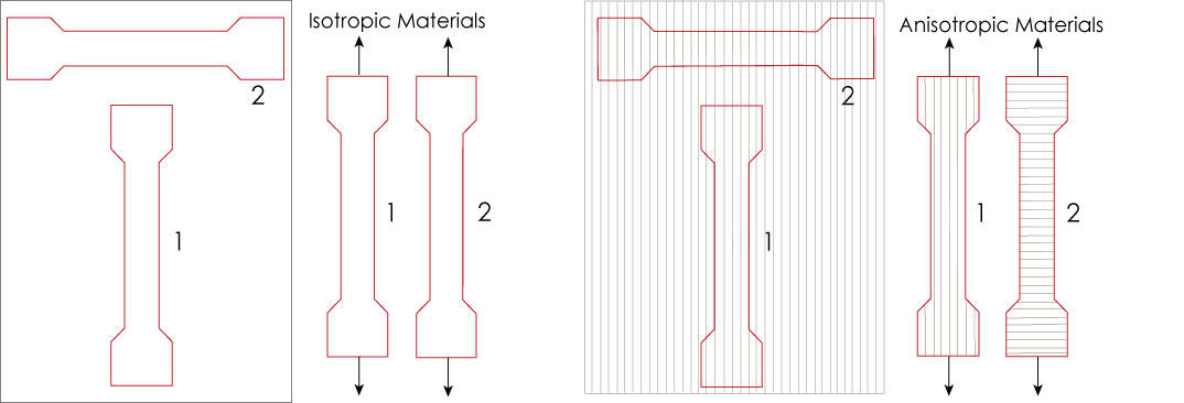
Anisotropic materials are materials whose properties vary when measured in different directions. Fiber-reinforced materials such as composites frequently display anisotropic properties and can demonstrate great strength when force is applied in the same direction as the fibers, and much less strength when force is applied in the opposite direction. Anisotropy can also be observed in other materials like metals, where processing or forming operations such as rolling or deep drawing have been performed. Materials with uniform directional strength are referred to as "isotropic".

anisotropic vs isotropic

Related Content

3400 Series Universal Testing Systems Brochure

Instron 3400 Series universal testing systems for tensile, compression, bend, and other material property tests.

6800 Series Premier Testing Systems Brochure

Instron 6800 Series Universal Testing Systems provide unparalleled accuracy and reliability. Built on a patent-pending Operator Protect system architecture with an all-new Smart-Close Air Kit and Collision Mitigation features, the 6800 Series makes materials testing simpler, smarter, and safer than ever before.

Bluehill Universal Brochure

Bluehill Universal is Instron’s advanced materials testing software, designed for intuitive touch interaction and streamlined workflows. It offers pre-loaded test methods, QuickTest for rapid setup, enhanced data exporting, and Instron Connect for direct service communication. Users of Bluehill 2 and Bluehill 3 can easily upgrade to the latest version for improved performance and usability.

Actuator


Actuator
»
Page 2


Actuator

A rod, mounted on the load frame that is driven up or down using servohydraulic force. The force required to drive the actuator is transferred to the specimen through the grips. Actuator applies to servohydraulic systems only. Note that the crosshead is fixed during a test on a servohydraulic system.

Related Content

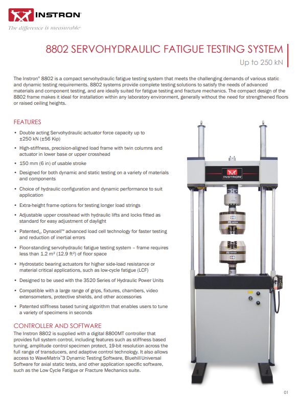
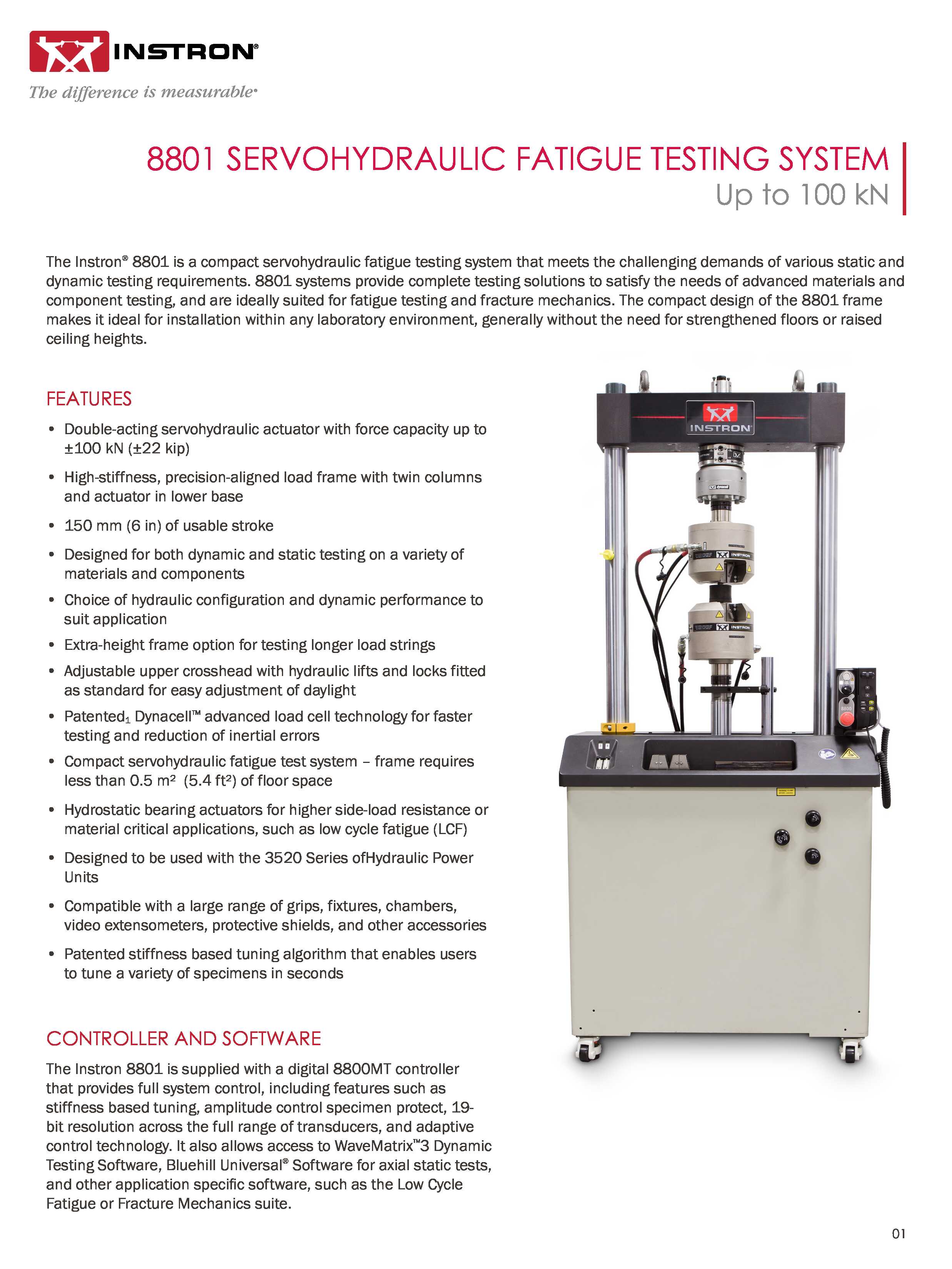
8801 Series Servohydraulic Fatigue Testing Systems

The Instron® 8801 is a compact servohydraulic fatigue testing system that meets the challenging demands of various static and dynamic testing requirements. 8801 systems provide complete testing solutions to satisfy the needs of advanced materials and component testing, and are ideally suited for fatigue testing and fracture mechanics. The compact design of the 8801 frame makes it ideal for installation within any laboratory environment, generally without the need for strengthened floors or raised ceiling heights.

8802 Servohydraulic Fatigue Testing System

The Instron® 8802 is a versatile servohydraulic fatigue testing system that meets the challenging demands of a varied range
of static and dynamic testing requirements. 8802 systems provide complete testing solutions to satisfy the needs of advanced
materials and component testing, and are ideally suited for fatigue testing and fracture mechanics. With a large number of
configurations and options available, the 8802 system provides a versatile platform for any laboratory.

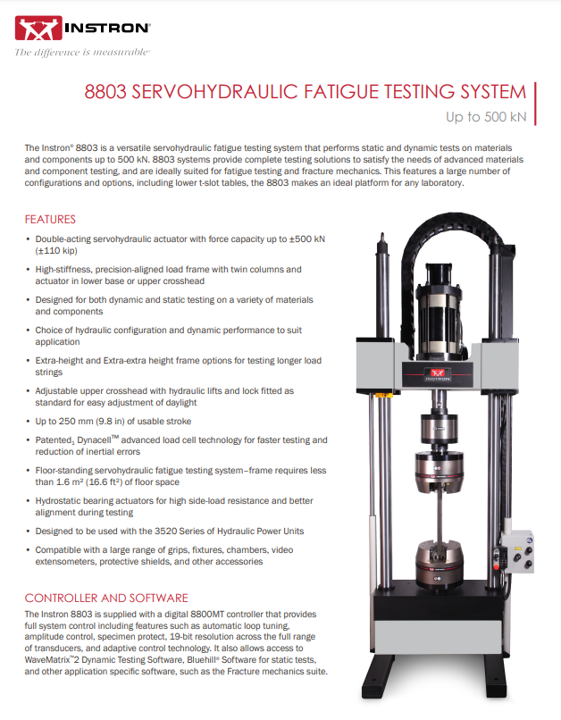
8803 Servohydraulic Fatigue Testing System

The Instron® 8803 is a versatile servohydraulic fatigue testing system that performs static and dynamic tests on materials and
components up to 500 kN. 8803 systems provide complete testing solutions to satisfy the needs of advanced materials
and component testing, and are ideally suited for fatigue testing and fracture mechanics. With a large number of configurations
and options, including lower t-slot tables, the 8803 makes an ideal platform for any laboratory.

8872 Servohydraulic Fatigue Testing System

The Instron® 8872 is a compact tabletop servohydraulic testing system that meets the challenging demands of various static
and dynamic testing requirements. With the actuator in the upper crosshead and a lower t-slot table, the 8872 makes an ideal
platform for a variety of medical devices, biomaterials, advanced materials, and other component testing.

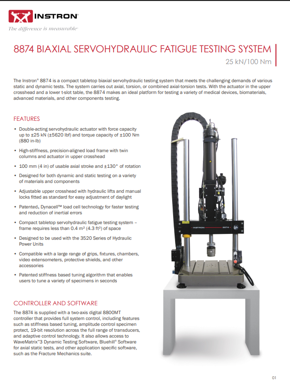
8874 Servohydraulic Fatigue Testing System

The Instron® 8874 is a compact tabletop axial-torsion servohydraulic testing system that meets the challenging demands various static and dynamic tests requires. The system carries out axial, torsion, or combined axial-torsion tests. With the actuator in the upper crosshead and a lower t-slot table, the 8874 makes an ideal platform for testing a variety of medical devices, biomaterials, advanced materials, and other components testing.

Secant Modulus of Elasticity

Secant Modulus of Elasticity

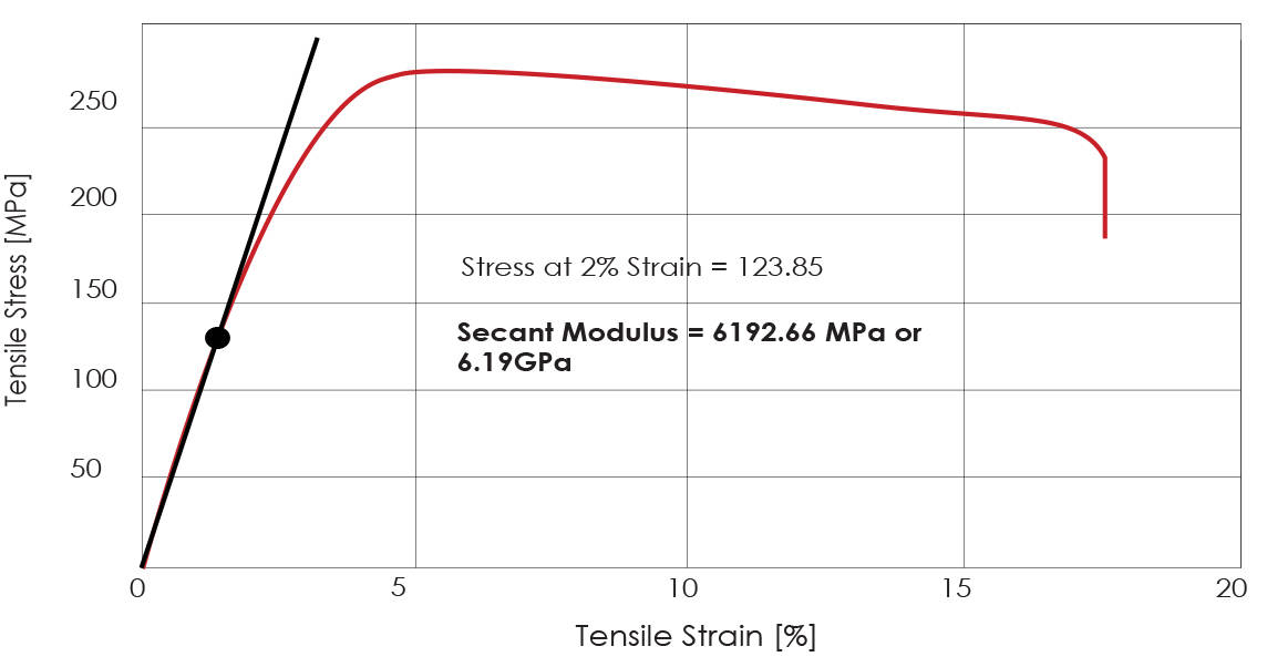
Secant modulus is one of several methods used to calculate modulus of elasticity, which is a measurement of a material's elasticity. Calculating secant modulus involves using two points on a stress-strain curve to calculate the slope of the stress/strain. When using this method, the first point is always zero and the second is always a non-zero value. For example, if secant modulus is calculated at 2% tensile strain, the formula for the calculation is: Secant Modulus = (σ2 - σ1) / (ε2 - ε1) = (Stress @ 2% Strain - 0) / (2% Strain – 0)

secant modulus

Related Content

3400 Series Universal Testing Systems Brochure

Instron 3400 Series universal testing systems for tensile, compression, bend, and other material property tests.

6800 Series Premier Testing Systems Brochure

Instron 6800 Series Universal Testing Systems provide unparalleled accuracy and reliability. Built on a patent-pending Operator Protect system architecture with an all-new Smart-Close Air Kit and Collision Mitigation features, the 6800 Series makes materials testing simpler, smarter, and safer than ever before.

Bluehill Universal Brochure

Bluehill Universal is Instron’s advanced materials testing software, designed for intuitive touch interaction and streamlined workflows. It offers pre-loaded test methods, QuickTest for rapid setup, enhanced data exporting, and Instron Connect for direct service communication. Users of Bluehill 2 and Bluehill 3 can easily upgrade to the latest version for improved performance and usability.

Proportional Limit

Proportional Limit » Page 2

Proportional Limit

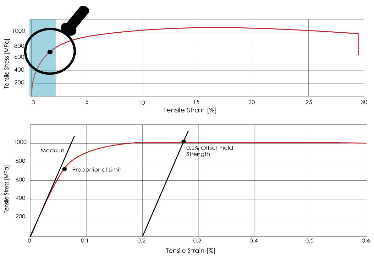
The proportional limit is the point on a stress-strain curve where the linear, elastic deformation region transitions into a non-linear, plastic deformation region. In other words, the proportional limit determines the greatest stress that is directly proportional to strain. The transition point can be calculated by a specified percent change in slope. Because the proportional limit is not required by many test standards,  it is often used for educational purposes rather than in practice by the materials testing industry.

How is Proportional Limit Different from Elastic Limit?

The elastic limit is the greatest stress that can be applied to a material without causing plastic (permanent) deformation. For many materials the elastic limit is equivalent or nearly equivalent to the proportional limit. For other materials, such as elastomers, the stress-strain relationship is non-linear and the material will still be within its elastic region long after it has passed through its proportional limit. The elastic limit is essentially a theoretical value that is difficult to determine using a universal testing machine, and for this reason is used mainly for educational purposes rather than in practice by the materials testing industry.

How is Proportional Limit Different from Yield Strength?

Similar to the elastic limit, the yield strength of a material can also occur beyond the material’s proportional limit. Unlike the elastic limit, the yield strength on a stress-strain curve has been defined by ASTM and ISO test standards. Depending on the material’s stress-strain behavior at yield, a preferred yield calculation is specified by the chosen standard. For instance, metals test standards (ASTM E8 or ISO 6892) have standardized a 0.2% offset yield, which allows the metals industry to objectively evaluate different metals against each other. The stress-strain curve below displays the difference between the proportional limit (4% change in slope) and the 0.2% offset yield point in a metals test.

the difference between the proportional limit example
Related Content

3400 Series Universal Testing Systems Brochure

Instron 3400 Series universal testing systems for tensile, compression, bend, and other material property tests.

6800 Series Premier Testing Systems Brochure

Instron 6800 Series Universal Testing Systems provide unparalleled accuracy and reliability. Built on a patent-pending Operator Protect system architecture with an all-new Smart-Close Air Kit and Collision Mitigation features, the 6800 Series makes materials testing simpler, smarter, and safer than ever before.

Bluehill Universal Brochure

Bluehill Universal is Instron’s advanced materials testing software, designed for intuitive touch interaction and streamlined workflows. It offers pre-loaded test methods, QuickTest for rapid setup, enhanced data exporting, and Instron Connect for direct service communication. Users of Bluehill 2 and Bluehill 3 can easily upgrade to the latest version for improved performance and usability.

Offset Yield Strength

Offset Yield Strength

Offset yield strength is an arbitrary approximation of a material's elastic limit. It is the stress that corresponds to a point at the intersection of a stress-strain curve and a line which is parallel to a specified modulus of elasticity line. This parallel line is horizontally offset by a predetermined amount. The intersection point represents the yield point of the material being tested. The value of the offset (expressed as a percentage of strain) is arbitrarily defined by the material testing standard (ASTM or ISO) being used. The most common offset is 0.2%, but this can vary depending on the material. By the time the material reaches its offset yield point, it usually will have surpassed its elastic limit and experienced a small percentage of plastic strain approximately equivalent to the offset value. The testing industry has accepted this standardized approach as one method to determine the yield strength of materials that do not have an easily discernible yield point.

How is Offset Yield Strength Different from Elastic Limit?

The elastic limit is the greatest stress that can be applied to a material without causing plastic deformation. The offset yield point differs from the elastic limit, as offset yield will generally occur beyond the material's elastic limit.

How is Offset Yield Strength Different from Proportional Limit?

The proportional limit is the point on a stress-strain curve where the linear, elastic deformation region transitions into a non-linear, plastic deformation region. Offset yield strength differs from the proportional limit as offset yield can be beyond a material's linear region.

proportional limit illustration

Related Content

3400 Series Universal Testing Systems Brochure

Instron 3400 Series universal testing systems for tensile, compression, bend, and other material property tests.

6800 Series Premier Testing Systems Brochure

Instron 6800 Series Universal Testing Systems provide unparalleled accuracy and reliability. Built on a patent-pending Operator Protect system architecture with an all-new Smart-Close Air Kit and Collision Mitigation features, the 6800 Series makes materials testing simpler, smarter, and safer than ever before.

Bluehill Universal Brochure

Bluehill Universal is Instron’s advanced materials testing software, designed for intuitive touch interaction and streamlined workflows. It offers pre-loaded test methods, QuickTest for rapid setup, enhanced data exporting, and Instron Connect for direct service communication. Users of Bluehill 2 and Bluehill 3 can easily upgrade to the latest version for improved performance and usability.

Izod (Impact)

Izod (Impact) » Page 2

Izod (Impact)

What is an Izod pendulum impact test?

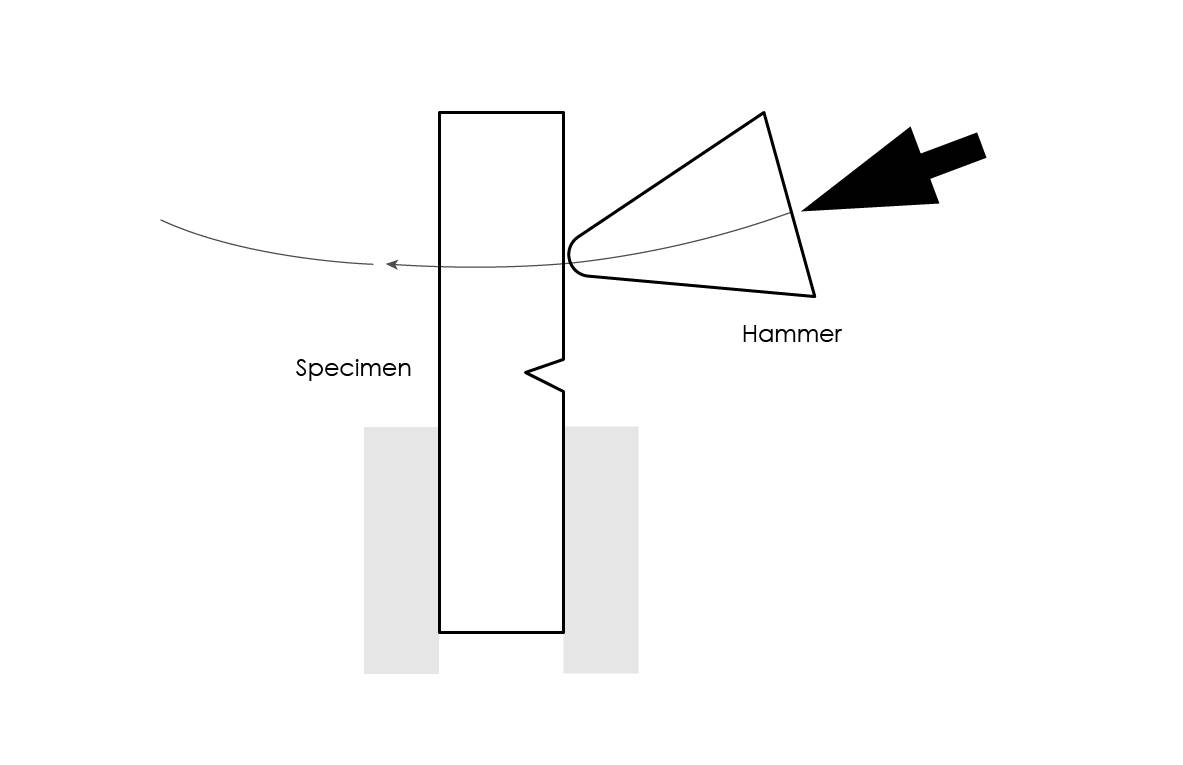
A test for determining toughness, or the tendency of a material to resist breaking on being subjected to sudden shock. It involves notching a bar on the test specimen, clamping one end (in a cantilever beam configuration) and striking the other end so it breaks off.

Izod pendulum impact test being performed

How is an Izod pendulum impact test performed?

Typically executed on a pendulum testing machine, Izod impact test can be performed on both notched or unnotched specimens by the support. It is standardized in the ISO 180 and ASTM D256. The test specimen is clamped into the specimen support in a position so that the notched end of the specimen is facing the striking edge of the pendulum. A properly positioned test specimen is showed in the following figure.

Once the pendulum is released, it strikes the specimen and swing through. If the specimen does not break, a higher energy hammer has to be used and the test should be repeated until failure is observed. For the Izod test, pendulum hammers according to standard ISO 13802 are used with a nominal impact energy range from 0.5J to 50J and impact velocities of 3.5 m/s. The impact strength (resilience) is calculated directly by dividing the impact value obtained from the measure by the thickness of the specimen (dimension J/m) or by the residual area under the notch (dimension kJ/m2).

This test method gives a higher stress than a Charpy test and may require a controlled clamping force for good repeatability. The manual specimen support can be tightened using a torque wrench while the clamping force can be adjusted using the lever or pneumatically-operated specimen supports.

Related Content

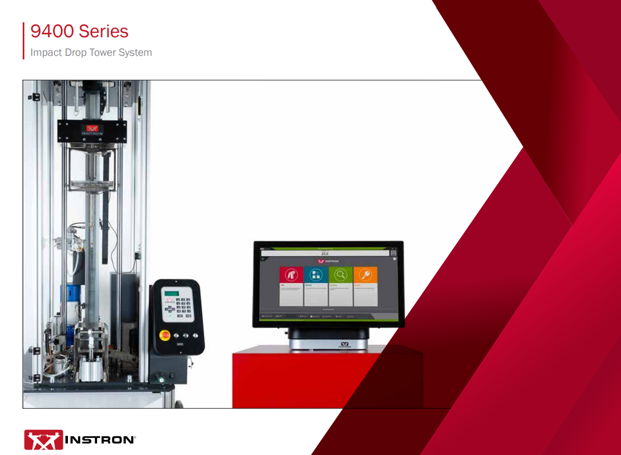
9400 Series Drop Tower Brochure

Instron Drop Towers are used to develop, fine tune, and validate material models. Testing materials under real impact conditions is a crucial step prior of product design. Using the characterization data obtained with the Instron 9400, coupled with customer supplied high-speed video, you can have confidence in your results and deliver new materials to your customers faster. Our Drop Tower impact systems, fixtures, and tups are designed to meet a wide range of applications and testing standards including: ISO, ASTM, ANSI, Airbus, Boeing, BSI, DIN, EN, FDA, Ford, GM, JIS, NASA, GOST, and more.

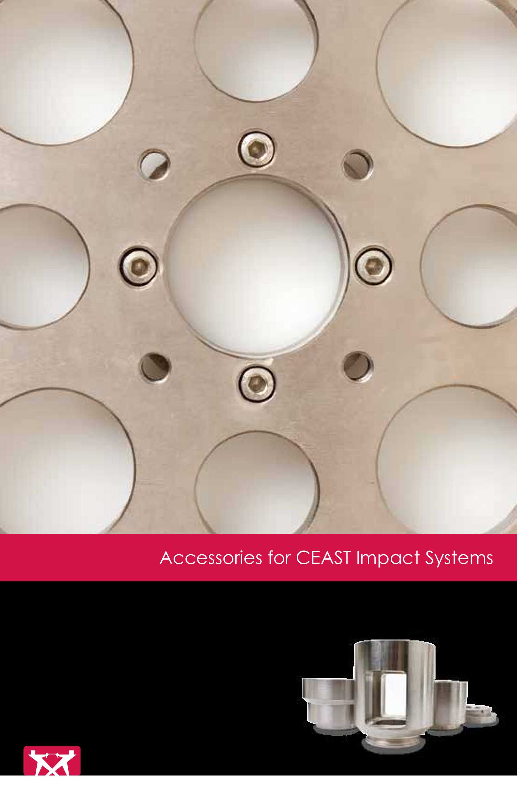
Accessories for CEAST Impact Systems

Accessories for CEAST Drop Tower and Pendulum Impact Testers.

Capillary Rheometer Die

Dies (Rheology)

A die is a solid piece of hardened steel or tungsten carbide that is finely machined into a cylindrical shape before a cylindrical hole (capillary) is bored through its center, normally by means of electro-erosion techniques. The term ‘capillary’ is sometimes used to indicate the whole die. Dies can be made of different materials such as stainless steel (Stavax) or nickel alloys (Hastelloy) for use with corrosive samples. The sample under test flows out through the capillary. Dies for rheology are used in melt flow instruments and capillary rheometers. They come in a range of different “geometries” to suit different applications and meet the requirements of different standards.

Dies are described by the length and diameter of the capillary, and by the shape of the capillary inlet. Dies are often described by their ‘length over diameter ratio’ or ‘L/D’ and entry angle: e.g. if the capillary length is 20 mm and the diameter is 1 mm, with an inlet consisting of a 90°-opening cone, it will be described as a die with 1-mm diameter capillary, L/D= 20, conical 90° inlet. A flat inlet corresponds to 180°. Special dies can be machined having a very short capillary, normally in the range of 0.25 mm: they are called ‘orifice dies’ or ‘zero-length dies’ and can be used for direct measurement of entrance pressure drop.

The standard die for melt flow tests has a capillary with a diameter of 2.095 mm and a length of 8 mm, with a flat inlet. Special methods call for longer dies, also with conical inlet (ASTM D3364 for tests on PVC).

Dies for capillary rheometers range in diameter from less than 0.5 mm to more than 2 mm, from ‘zero-length’ up to 40 mm or more in length. Inlet shape is normally flat or 90° conical.

Standards recommend for Bagley correction at least two different dies with same capillary diameter and different lengths, while other combinations are required for different applications (e.g. two dies with same L/D for Mooney wall slip evaluation).

References

  • ISO 11443: 2005 “Determination of the fluidity of plastics using capillary and slit-die rheometers”
  • ISO 1133:2005 "Plastics - Determination of the Melt Mass-Flow Rate (MFR) and Melt Volume-Flow Rate (MVR) of Thermoplastics”
  • ASTM D3835-09 “Standard Test Method for Determination of Properties of Polymeric Materials by Means of a Capillary Rheometer”
  • ASTM D1238-10 "Standard Test Method for Melt Flow Rates of Thermoplastics by Extrusion Plastometer“

Related Content

Capillary Rheometer Systems

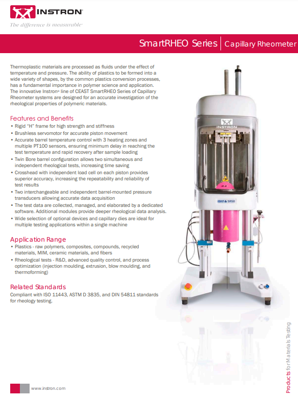
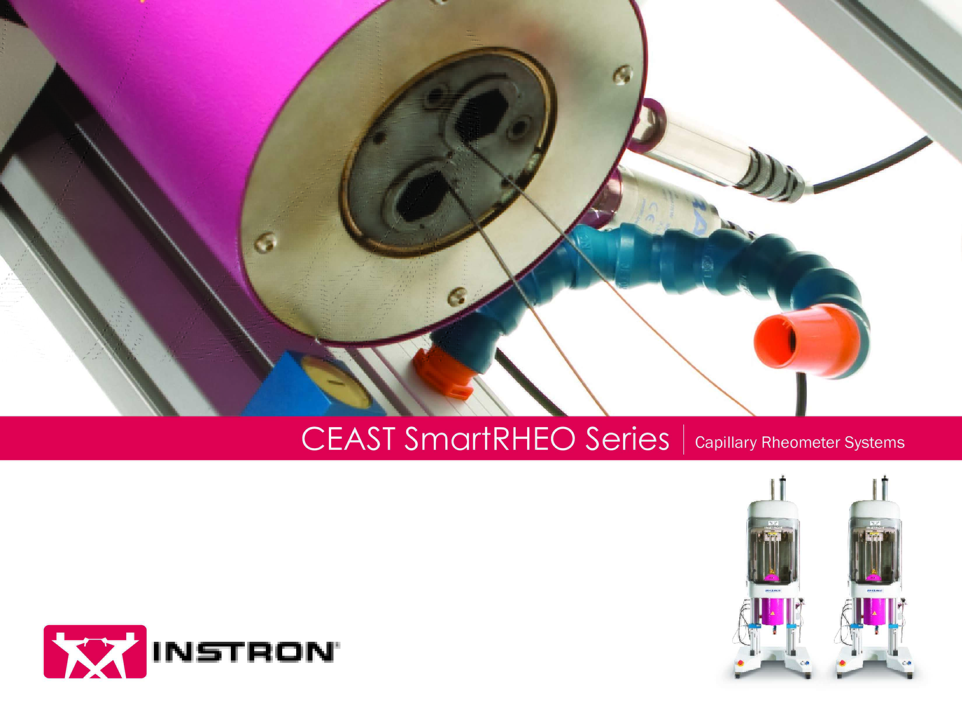
The innovative Instron® line of CEAST SmartRHEO Series of Capillary Rheometer systems are designed for an accurate investigation of the rheological properties of polymeric materials.

CEAST SmartRHEO Series: Capillary Rheometer Systems

Thermoplastic materials are processed as fluids under the effect of temperature and pressure. The ability of plastics to be formed into a wide variety of shapes, by the common plastics conversion processes, has a fundamental importance in polymer science and application. The innovative Instron® line of CEAST SmartRHEO Series of Capillary Rheometer systems are designed for an accurate investigation of the rheological properties of polymeric materials.

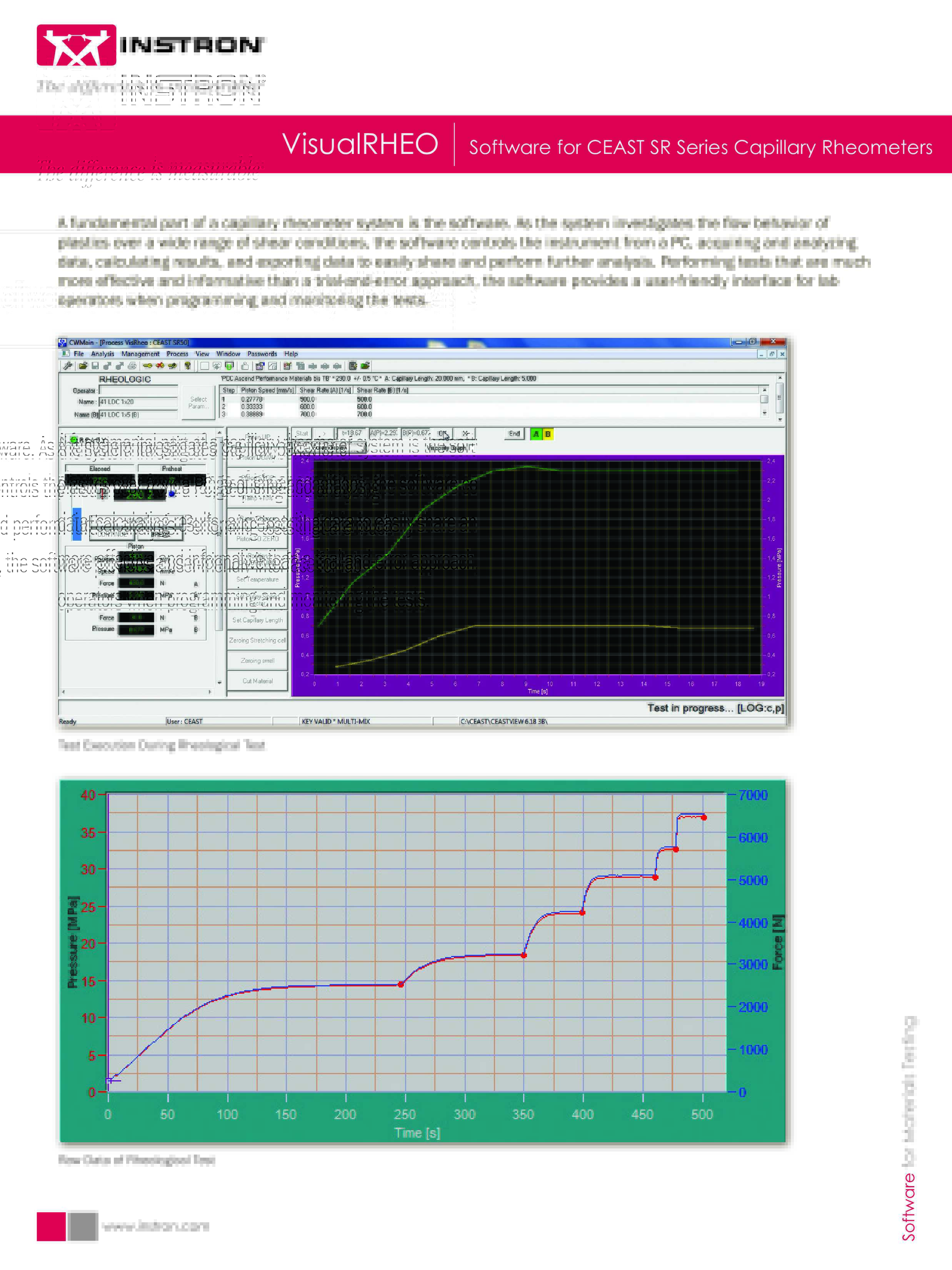
VisualRHEO | Software for CEAST SR Series Capillary Rheometers

A fundamental part of a capillary rheometer system is the software. As the system investigates the flow behavior of
plastics over a wide range of shear conditions, the software controls the instrument from a PC, acquiring and analyzing
data, calculating results, and exporting data to easily share and perform further analysis. Performing tests that are much
more effective and informative than a trial-and-error approach, the software provides a user-friendly interface for lab
operators when programming and monitoring the tests.

Melt Flow


Melt Flow
»
Page 2


Melt Flow Rate (MFR, MVR)

The Melt Flow Rate is a measure of the ease of flow of melted plastic and represents a typical index for Quality Control of thermoplastics. Originally called Melt Flow Index or Melt Index (typically for polyethylene, but applied to a variety of materials), the standard designation today is Melt Mass-Flow Rate or MFR, which is a mass flow expressed (SI units) in g/10min. An alternative quantity is the volume flow expressed (SI units) in cm3/10min, called Melt Volume-Flow Rate or MVR. MVR multiplied by the melt density (i.e. density of the material in the melted state) gives MFR.

Typical Melt Flow instruments are compact and easy to use. The basic principle is that a thermoplastic sample (originally in the shape of granules, powder or flakes) is made fluid by heating and forced to flow out of a cylinder through a capillary die. The extruding piston is loaded with dead weights, normally up to 21.6 kg. MFR (and MVR) are obtained under standard conditions of temperature and applied load, defined for each type of material, and normally using a fixed type of die (inner diameter 2.095 mm, length 8 mm). The result must always specify the test conditions because it’s strongly dependent on those.

MFR and MVR are typically used in Quality Control labs and Production Control labs. The basic procedure foresees a manual timing, cutting and weighing of the extruded material, giving directly a value of MFR. Semi-automatic procedures allowed by modern instruments are based on direct measurements of piston displacement, hence they give directly a value of MVR. Melt density can be typed in or measured, and therefore MFR results are also obtained. Semi-automatic procedures can achieve a much higher accuracy and guarantee a wider range of measurable flow rates. More advanced methods foresee the application of several loads during the same test, each one giving a MFR (MVR) result. This is called a multiweight test and gives additional information on the sample, with some insight on the shear dependence of viscosity. A single-weight MFR test can be correlated with average molecular mass, while the shear dependence depends on the molecular mass distribution.

Melt flow rate is a quick tool to compare batches of the same material or to estimate flow properties of different materials (typically for extrusion processes), when a deep understanding of material properties is not required. A true rheological characterization can be carried out by means of rheometers. Melt flow rate is inversely proportional to (shear) viscosity, but is not used to determine the latter (can give just a rough estimation).

References:

  • ISO 1133:2005 "Plastics - Determination of the Melt Mass-Flow Rate (MFR) and Melt Volume-Flow Rate (MVR) of Thermoplastics”
  • ASTM D1238-10 "Standard Test Method for Melt Flow Rates of Thermoplastics by Extrusion Plastometer“

Testing Equipment

Melt Flow tests are performed on melt flow testers table top machines such as Instron's MF20 and MF30. These machines are available in a variety of different sizes. Depending on the number of masses needed for your material, the machines can be equipped with automatic weight lifter.

Related Content

CEAST Melt Flow Series Brochure

Flow properties of molten plastics are a critical characteristic requiring good knowledge and control. The Instron® Melt Flow Testers are specifically designed for easy
and accurate measuring of the Melt Mass-Flow Rate (MFR) and the Melt Volume-Flow Rate (MVR). CEAST Melt Flow Testers range from systems that perform a simple
manual test procedure to semi-automated testing systems performing multiple weight tests.

CEAST Melt Flow Testers (MF20 and MF30)

The CEAST line of melt flow testers now includes the MF20 and MF30 Melt Flow Testers, which meet the stricter requirements imposed by ISO 1133-2 with regard to temperature control for highly sensitive materials.

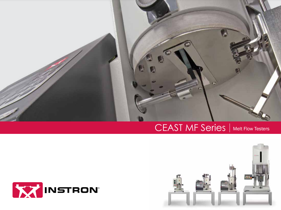
CEAST MF Series Brochure

Flow properties of molten plastics are a critical characteristic requiring good knowledge and control. The Instron® Melt Flow Testers are specifically designed for easy and accurate measuring of the Melt Mass-Flow Rate (MFR) and the Melt Volume-Flow Rate (MVR). CEAST Melt Flow Testers range from systems that perform a simple manual test procedure to semi-automated testing systems performing multiple weight tests.

Instron® Professional Services CEAST Melt Flow and HDT Vicat Verification Services

Preventative maintenance and verification of your Melt Flow or HDT Vicat Testing System helps avoid potential risk exposure from inaccurate test results that can affect the quality of your product to market.To report accurate and repeatable results, it is important to ensure your materials testing system is operating at peak performance and verified in conformance with the relevant material testing standards.

Uncertainty of Measurement

Uncertainty of Measurement

If measurements cannot be perfectly exact, we need to know the size of the imperfection; this is Uncertainty of Measurement.

To best try to explain what Uncertainty of Measurement is, let us consider a simple task. Imagine measuring the length of a piece of string. If we gave our piece of string to a group of 10 people and asked them to measure it we would most likely receive 10 different answers. The reason for this would be due to Sources of Uncertainty. This could include:

  • Straightness of the string
  • End flatness of string (raggedness of the end fibers)
  • Tension of the string
  • Humidity affecting the string
  • Temperature affecting the string
  • Resolution of the ruler (the smallest division on the ruler)
  • Correctness of the ruler (how perfect was the ruler when it was calibrated)
  • Correctness of measurement of the master device used to calibrate the ruler
  • How many readings taken to determine the measurement length
  • Repeatability of the measurements

As you can now see the environment, method, and equipment all contribute opportunities for variations and doubt. And we have to conclude that:

  • Nothing is CERTAIN in measurement
  • The only certainty is that any measurement will not be perfectly exact

Quantifying the Uncertainty of a Measurement can be a complicated, but methodical task. The International Standards Organisation (ISO) has produced a document called The Guide to the Uncertainty of Measurement (GUM), which provides internationally recognized methods for determination of Uncertainty Budgets and associated calculations. More recently, many ISO and ASTM standards also include appendices detailing how to work out uncertainty of measurement. Because measurement variation is a major contribution in any Uncertainty Budget, probability as well as size of variation has to be defined when expressing Uncertainty of Measurement.

Related Content

3400 Series Universal Testing Systems Brochure

Instron 3400 Series universal testing systems for tensile, compression, bend, and other material property tests.

6800 Series Premier Testing Systems Brochure

Instron 6800 Series Universal Testing Systems provide unparalleled accuracy and reliability. Built on a patent-pending Operator Protect system architecture with an all-new Smart-Close Air Kit and Collision Mitigation features, the 6800 Series makes materials testing simpler, smarter, and safer than ever before.

Bluehill Universal Brochure

Bluehill Universal is Instron’s advanced materials testing software, designed for intuitive touch interaction and streamlined workflows. It offers pre-loaded test methods, QuickTest for rapid setup, enhanced data exporting, and Instron Connect for direct service communication. Users of Bluehill 2 and Bluehill 3 can easily upgrade to the latest version for improved performance and usability.

Transducer


Transducer
»
Page 2


Transducer

A device which converts a physical property such as force, motion, temperature, and so on, into a proportional electrical signal which is used to measure the property. A load transducer, or load cell, converts load into an electrical signal, and an extensometer converts specimen extension into an electrical signal.

Related Content

3400 Series Universal Testing Systems Brochure

Instron 3400 Series universal testing systems for tensile, compression, bend, and other material property tests.

6800 Series Premier Testing Systems Brochure

Instron 6800 Series Universal Testing Systems provide unparalleled accuracy and reliability. Built on a patent-pending Operator Protect system architecture with an all-new Smart-Close Air Kit and Collision Mitigation features, the 6800 Series makes materials testing simpler, smarter, and safer than ever before.

Bluehill Universal Brochure

Bluehill Universal is Instron’s advanced materials testing software, designed for intuitive touch interaction and streamlined workflows. It offers pre-loaded test methods, QuickTest for rapid setup, enhanced data exporting, and Instron Connect for direct service communication. Users of Bluehill 2 and Bluehill 3 can easily upgrade to the latest version for improved performance and usability.

True Stress


True Stress
»
Page 2


True Stress

Applied load divided by actual area of the cross section through which load operates. It takes into account the change in cross section that occurs with changing load.

Related Content

3400 Series Universal Testing Systems Brochure

Instron 3400 Series universal testing systems for tensile, compression, bend, and other material property tests.

6800 Series Premier Testing Systems Brochure

Instron 6800 Series Universal Testing Systems provide unparalleled accuracy and reliability. Built on a patent-pending Operator Protect system architecture with an all-new Smart-Close Air Kit and Collision Mitigation features, the 6800 Series makes materials testing simpler, smarter, and safer than ever before.

Bluehill Universal Brochure

Bluehill Universal is Instron’s advanced materials testing software, designed for intuitive touch interaction and streamlined workflows. It offers pre-loaded test methods, QuickTest for rapid setup, enhanced data exporting, and Instron Connect for direct service communication. Users of Bluehill 2 and Bluehill 3 can easily upgrade to the latest version for improved performance and usability.