Extensometer

Extensometer » Page 5

Extensometer

Instrument to measure deformation of a test piece, based on changes from an initial reference geometry (typically with a fixed gauge length, such as 25mm or 50mm). This provides more accurate test piece extension than using overall machine movement, since it is not influenced by deformations outside the actual specimen, such as machine and grip compliance.

Related Content

AVE 2 Non-Contacting Video Extensometer

The second generation Advanced Video Extensometer (AVE 2) utilizes patented measurement technology in the fastest, most accurate non-contacting strain measurement device commercially available.
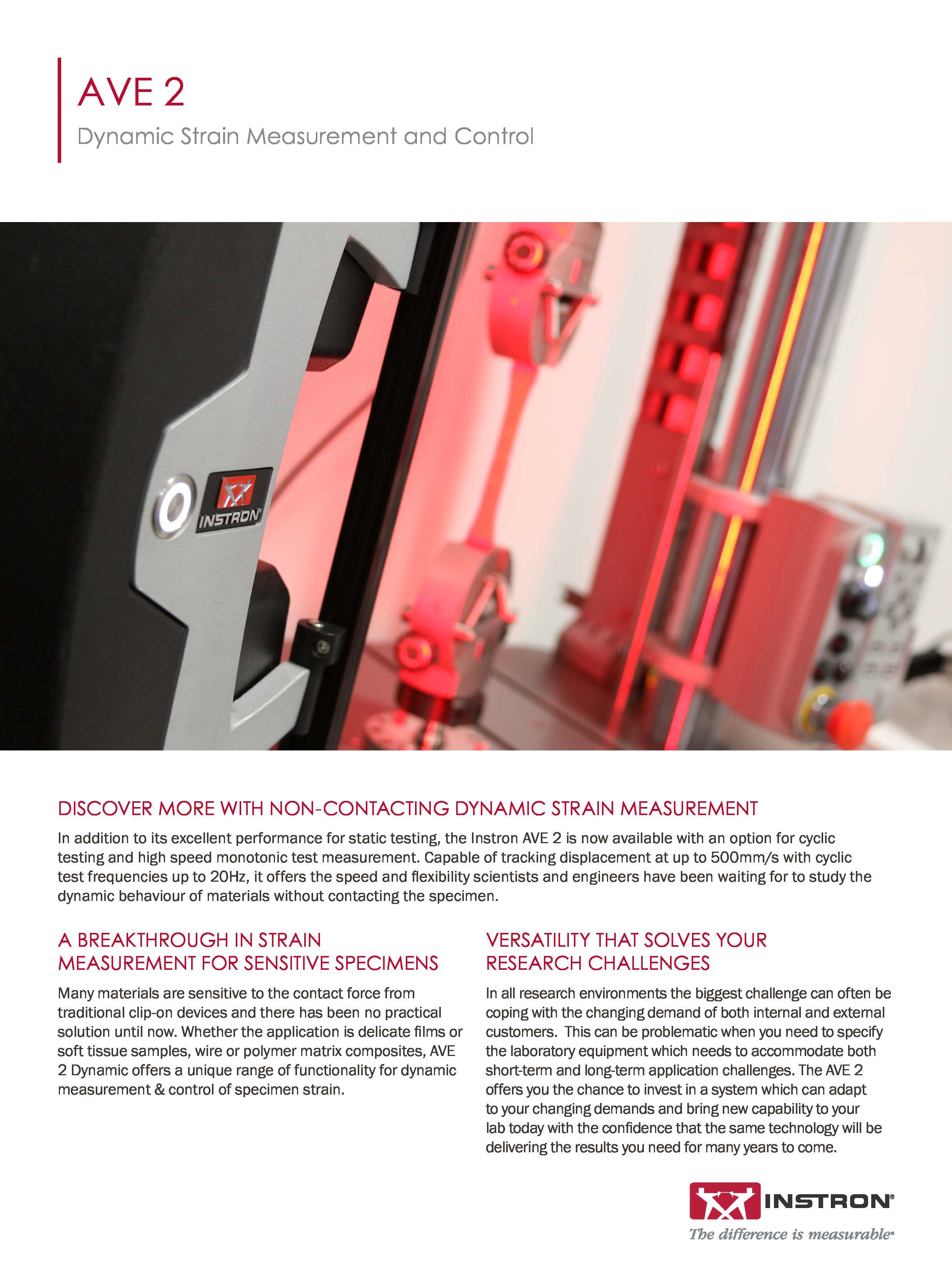
AVE2 Dynamic Strain Measurement

In addition to its excellent performance for static testing, the Instron AVE 2 is now available with an option for cyclic testing and high speed monotonic test measurement. Capable of tracking displacement at up to 500mm/s with cyclic test frequencies up to 20Hz, it offers the speed and flexibility scientists and engineers have been waiting for to study the dynamic behaviour of materials without contacting the specimen.

2603-080 Long Travel Extensometer

The Instron model XL (long travel) extensometer is a precise device for measuring strain in highly extensible materials such as elastomers, semi-rigid plastics, and films.
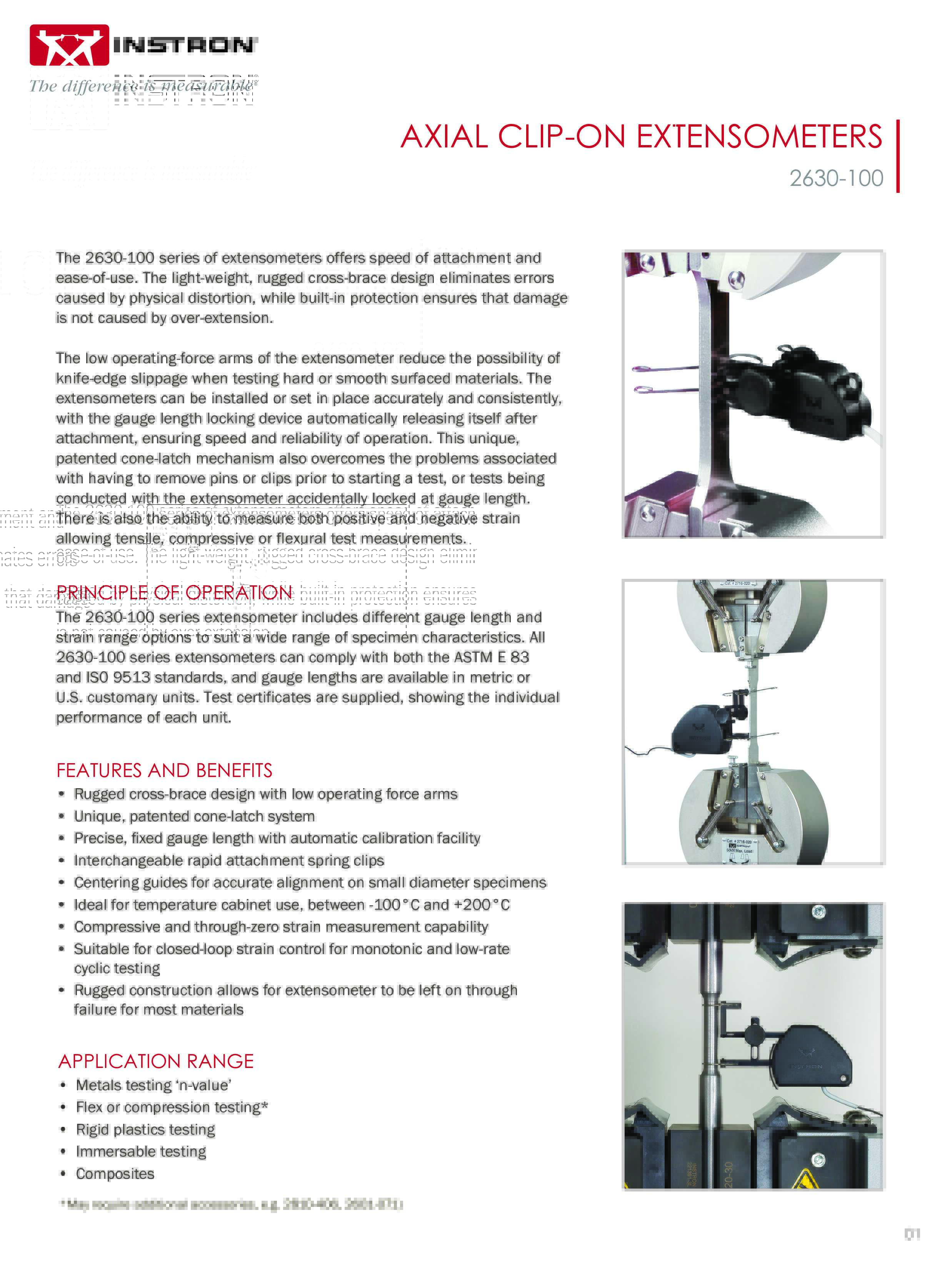
2630 Series Strain Gauge Extensometers

The 2630-100 series of extensometers offers speed of attachment and ease-of-use. The light-weight, rugged cross-brace design eliminates errors caused by physical distortion, while built-in protection ensures that damage is not caused by over-extension.
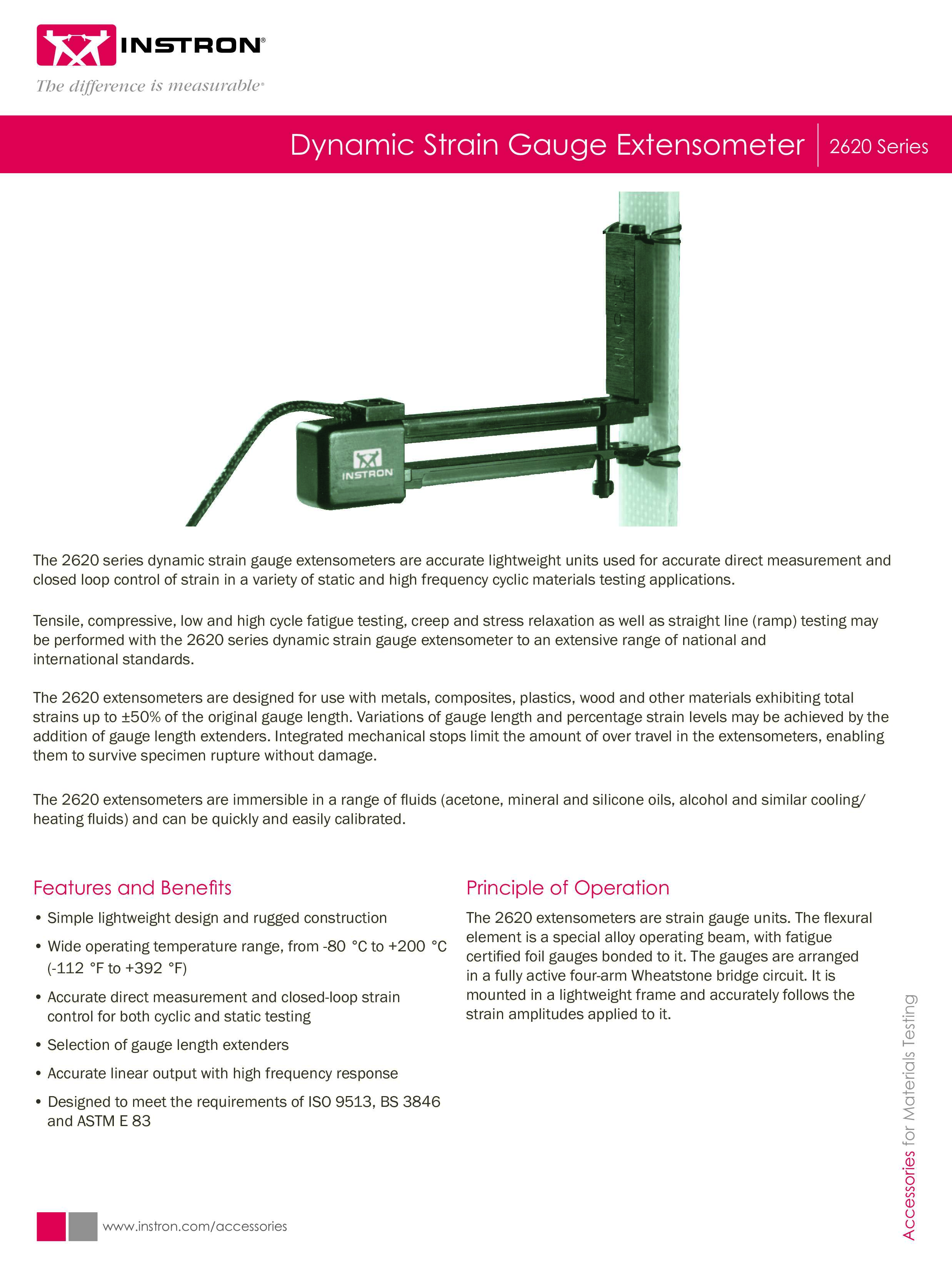
2620 Series Dynamic Strain Gauge Extensometer

Wide operating temperature range, from -80 °C to 200 °C (-112 °F to 392 °F)
Designed to meet the requirements of ISO 9513, BS 3846 and ASTM E 83

2630-100 Series Clip-On Extensometer – Reference Manual

These instructions describe the function, operation and maintenance for various models of the 2630-100 Series of Clip-On Extensometers.

2632 Series High Temperature Extensometers

The Instron strain-gauged extensometer measures small changes in length of test specimens at very high temperatures. It has been developed in conjunction with a number of advanced programs throughout the world investigating the properties of materials including alumina, silicon carbide, silicon nitride, carbon/carbon composites and other advanced ceramics.
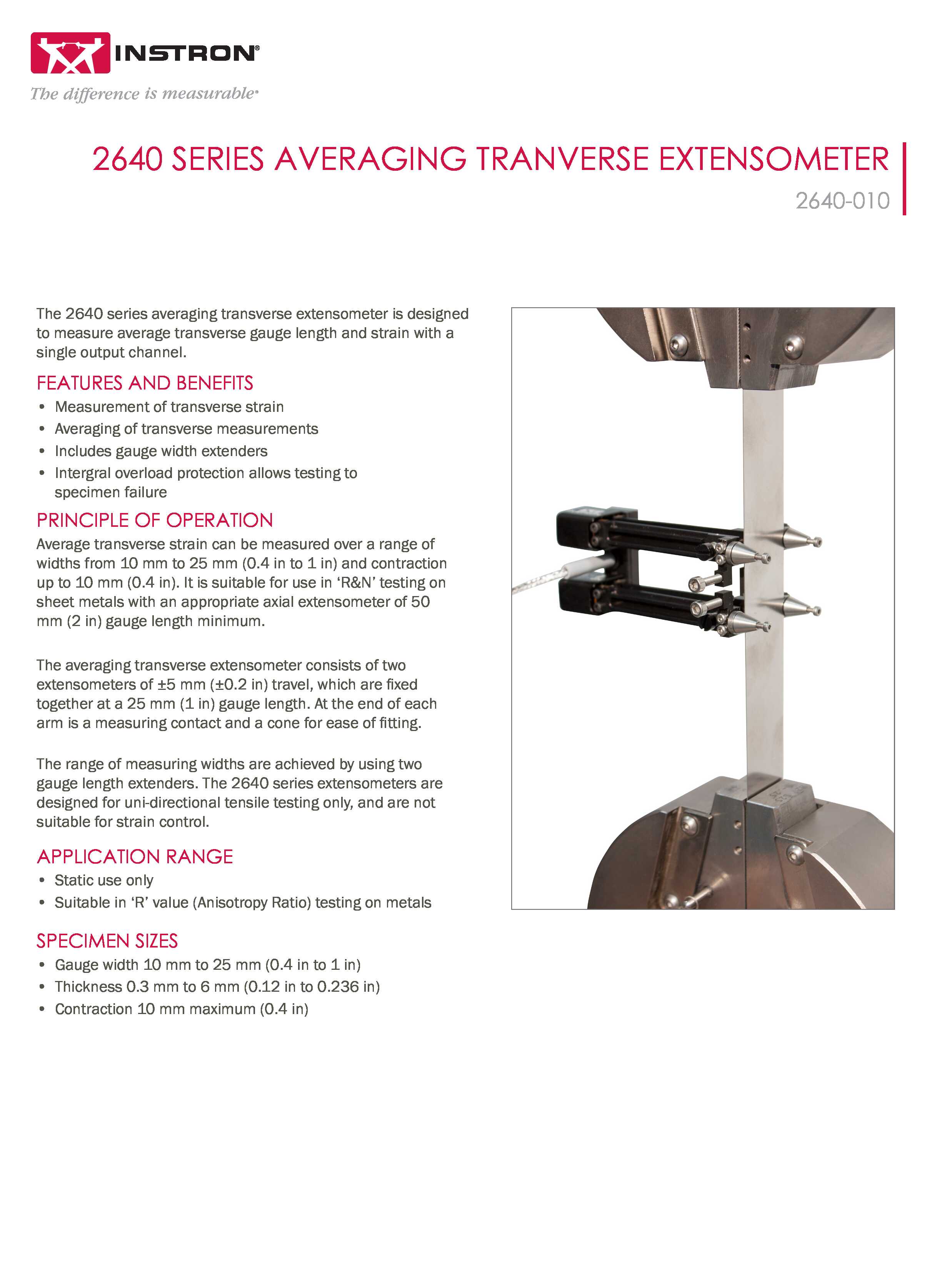
2640 Series Averaging Transverse Extensometer | 2640-010

The 2640 series averaging transverse extensometer is designed to measure average transverse gauge length and strain with a single output channel.

Fatigue

Fatigue » Page 5

Fatigue

Permanent structural change that occurs in a material subjected to fluctuating stress and strain. However, in the case of glass, fatigue is determined by long-term static testing and is analogous to stress rupture in other materials. In general, fatigue failure can occur with stress levels below the elastic limit.

Related Content

3400 Series Universal Testing Systems Brochure

Instron 3400 Series universal testing systems for tensile, compression, bend, and other material property tests.

6800 Series Premier Testing Systems Brochure

Instron 6800 Series Universal Testing Systems provide unparalleled accuracy and reliability. Built on a patent-pending Operator Protect system architecture with an all-new Smart-Close Air Kit and Collision Mitigation features, the 6800 Series makes materials testing simpler, smarter, and safer than ever before.

Bluehill Universal Brochure

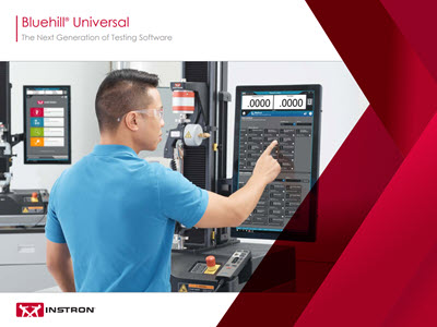
Bluehill Universal is Instron’s advanced materials testing software, designed for intuitive touch interaction and streamlined workflows. It offers pre-loaded test methods, QuickTest for rapid setup, enhanced data exporting, and Instron Connect for direct service communication. Users of Bluehill 2 and Bluehill 3 can easily upgrade to the latest version for improved performance and usability.

Elastic Limit

Elastic Limit » Page 5

Elastic Limit

A material's elastic limit is the greatest stress that can be applied to it without causing plastic (permanent) deformation. When a material is stressed to a point below its elastic limit, it will return to its original length once the stress is removed.  Once a material is stressed to a point exceeding its elastic limit, it begins to permanently yield, and when the stress is removed the material will not fully return to its original length. The elastic limit is difficult to accurately determine using a universal testing machine, which is why it is generally used for educational purposes rather than in practice by the materials testing industry.

How is Elastic Limit Different from Proportional Limit?

The proportional limit of a material is the point on a stress/strain curve where the linear, elastic deformation region transitions into the non-linear, plastic deformation region. A material's elastic limit can be equivalent to its proportional limit for certain materials, but for others, the stress/strain relationship will become nonlinear before reaching the material's elastic limit.

How is Elastic Limit Different from Yield Strength?

Similar to the elastic limit, the yield strength of a material is the stress that represents the transition point between elastic and plastic deformation. Unlike the elastic limit, which is impractical to precisely determine with a universal testing machine, yield strength can be determined through using various calculation methods accepted by the testing industry and outlined in a material's ASTM or ISO testing standard.

Related Content

3400 Series Universal Testing Systems Brochure

Instron 3400 Series universal testing systems for tensile, compression, bend, and other material property tests.

6800 Series Premier Testing Systems Brochure

Instron 6800 Series Universal Testing Systems provide unparalleled accuracy and reliability. Built on a patent-pending Operator Protect system architecture with an all-new Smart-Close Air Kit and Collision Mitigation features, the 6800 Series makes materials testing simpler, smarter, and safer than ever before.

Bluehill Universal Brochure

Bluehill Universal is Instron’s advanced materials testing software, designed for intuitive touch interaction and streamlined workflows. It offers pre-loaded test methods, QuickTest for rapid setup, enhanced data exporting, and Instron Connect for direct service communication. Users of Bluehill 2 and Bluehill 3 can easily upgrade to the latest version for improved performance and usability.

Contact Us

Connect with Instron's Sales, Service, Technical, or Training Support teams- our product and application experts are ready to assist you.

Elastic Hysteresis

Elastic Hysteresis » Page 5

Elastic Hysteresis

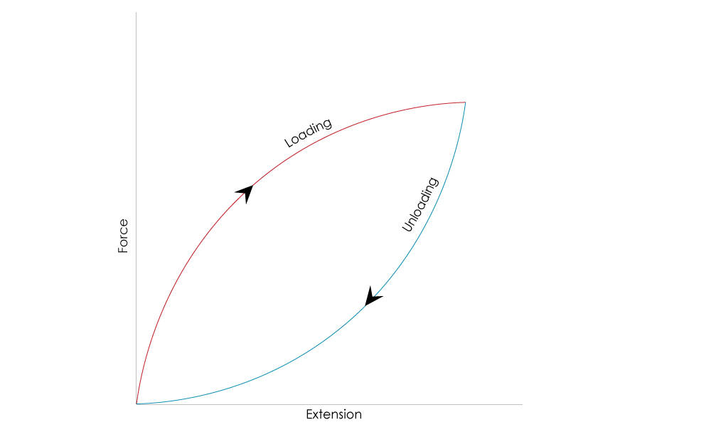
Elastic Hysteresis is the difference between the strain energy required to generate a given stress in a material, and the material's elastic energy at that stress. This energy is dissipated as internal friction (heat) in a material during one cycle of testing (loading and unloading).

When mechanical test data is plotted on a stress/strain curve, a material exhibiting elastic hysteresis will display one path during the loading phase of the test, and a different path during the unloading phase. The two paths will clearly diverge due to hysteresis loss (energy loss in the form of heat), with the area between the curves representing the energy dissipated.

Different materials display varying degrees of elastic hysteresis. Hard metals, for example, display less hysteresis than high-elongation materials such as elastomers. High-speed testing tends to generate the most noticeable results, as forces on the specimen will be greater over a shorter elongation, followed by a much quicker drop in load when unloading over that same elongation.

The damping capacity of a material can be found by dividing a material’s elastic hysteresis by its elastic deformation energy. By comparing the elastic hysteresis and damping capacities of different materials, engineers can make sure they are using a material appropriate for their intended application. For instance, a rubber with a more pronounced hysteresis is able to disperse a large amount of energy and might be a good choice for absorbing vibrations or sound.

elastic hysteresis
Related Content

3400 Series Universal Testing Systems Brochure

Instron 3400 Series universal testing systems for tensile, compression, bend, and other material property tests.

6800 Series Premier Testing Systems Brochure

Instron 6800 Series Universal Testing Systems provide unparalleled accuracy and reliability. Built on a patent-pending Operator Protect system architecture with an all-new Smart-Close Air Kit and Collision Mitigation features, the 6800 Series makes materials testing simpler, smarter, and safer than ever before.

Bluehill Universal Brochure

Bluehill Universal is Instron’s advanced materials testing software, designed for intuitive touch interaction and streamlined workflows. It offers pre-loaded test methods, QuickTest for rapid setup, enhanced data exporting, and Instron Connect for direct service communication. Users of Bluehill 2 and Bluehill 3 can easily upgrade to the latest version for improved performance and usability.

Contact Us

Connect with Instron's Sales, Service, Technical, or Training Support teams- our product and application experts are ready to assist you.

Elongation


Elongation
»
Page 5


Elongation

Measure of the ductility of a material determined in a tensile test. It is the increase in gage length (measured after rupture) divided by original gage length. Higher elongation indicates higher ductility. Elongation cannot be used to predict behavior of materials subjected to sudden or repeated loading.

Related Content

3400 Series Universal Testing Systems Brochure

Instron 3400 Series universal testing systems for tensile, compression, bend, and other material property tests.

6800 Series Premier Testing Systems Brochure

Instron 6800 Series Universal Testing Systems provide unparalleled accuracy and reliability. Built on a patent-pending Operator Protect system architecture with an all-new Smart-Close Air Kit and Collision Mitigation features, the 6800 Series makes materials testing simpler, smarter, and safer than ever before.

Bluehill Universal Brochure

Bluehill Universal is Instron’s advanced materials testing software, designed for intuitive touch interaction and streamlined workflows. It offers pre-loaded test methods, QuickTest for rapid setup, enhanced data exporting, and Instron Connect for direct service communication. Users of Bluehill 2 and Bluehill 3 can easily upgrade to the latest version for improved performance and usability.

Dynamic Mechanical Analysis (DMA)

Dynamic Mechanical Analysis (DMA)

Dynamic Mechanical Analysis (DMA) is a testing technique and related analytical instrument that measures the physical properties of solids and polymer melts, reports modulus and damping, and is programmable to measure force, stress, strain, frequency and temperature. DMA is also described as rheology of solids and also Dynamic Mechanical Thermal Analysis (DMTA) when combining the information with temperature response.

Theory

DMA instruments apply an oscillating force (stress) and record an oscillating sample response. Modulus is calculated from the elastic response; e.g. sample response “in phase” with applied oscillatory stress. Damping is calculated from the viscous response; e.g. sample response “out of phase” with applied oscillatory stress.

Equipment

A sample is held in place between two grips or confining elements. Next, an oscillatory (dynamic) force is applied to the sample. This is applied using an electric motor moving rotationally (typically back and forth) and linearly (typically up and down), and contains a frequency (speed of oscillation), and contains a force (energy input into sample).

Resulting strain (displacement) is measured typically using LVDT measurement but can also be a force transducer. Typically plots Storage Modulus and Tan Delta (damping) vs. Temperature.

Typically calculates Tg (the “glass transition”, typically melting of amorphous phase) and Beta transitions (low temperature declines in Modulus).

Methods

  1. Temperature Scan: Modulus and damping is recorded as the sample is heated
  2. Frequency Scan: Modulus and damping is recorded as the sample is vibrated at increasing speeds
  3. Stress Scan: Modulus and damping is recorded as the sample stress is increased
  4. Strain Scan: Modulus and damping is recorded as the sample strain is increased
  5. Transient Testing (not oscillatory): Creep-Relaxation and Stress-Recovery
  6. Multiplexed Scan: Combinations of above methods

Samples: Solid ASTM test bars / Films / Fibers, Melted polymers, Fluids.

Related Content

6800 Series | Safety Without Sacrificing Throughput

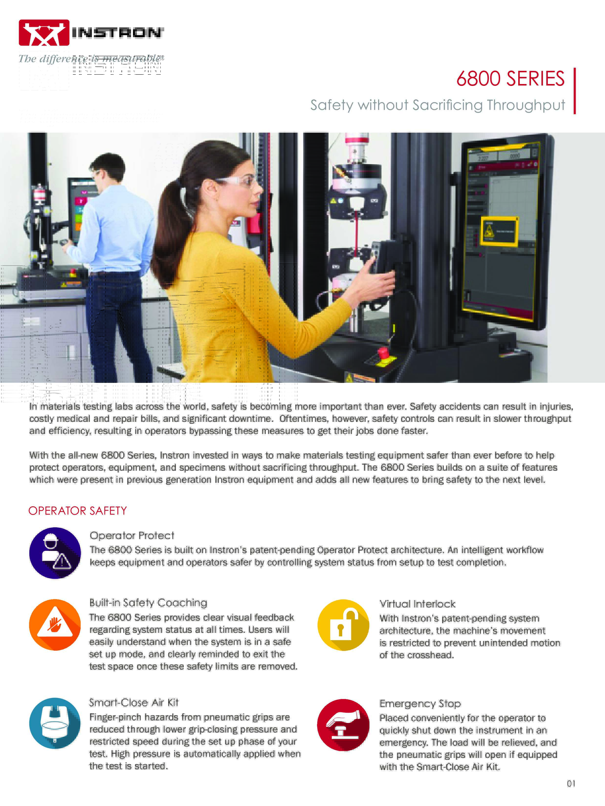
With the all-new 6800 Series, Instron invested in ways to make materials testing equipment safer than ever before to help protect operators, equipment, and specimens without sacrificing throughput.

6800 Series Premier Testing Systems Brochure

Instron 6800 Series Universal Testing Systems provide unparalleled accuracy and reliability. Built on a patent-pending Operator Protect system architecture with an all-new Smart-Close Air Kit and Collision Mitigation features, the 6800 Series makes materials testing simpler, smarter, and safer than ever before.

Crosshead


Crosshead
»
Page 5


Crosshead

A stiff beam, mounted on the load frame, that is driven up or down using electromechanical force. The force required to drive the crosshead is transferred to the specimen through the grips. Crosshead applies to electromechanical systems only.

Related Content

3400 Series Universal Testing Systems Brochure

Instron 3400 Series universal testing systems for tensile, compression, bend, and other material property tests.

6800 Series Premier Testing Systems Brochure

Instron 6800 Series Universal Testing Systems provide unparalleled accuracy and reliability. Built on a patent-pending Operator Protect system architecture with an all-new Smart-Close Air Kit and Collision Mitigation features, the 6800 Series makes materials testing simpler, smarter, and safer than ever before.

Bluehill Universal Brochure

Bluehill Universal is Instron’s advanced materials testing software, designed for intuitive touch interaction and streamlined workflows. It offers pre-loaded test methods, QuickTest for rapid setup, enhanced data exporting, and Instron Connect for direct service communication. Users of Bluehill 2 and Bluehill 3 can easily upgrade to the latest version for improved performance and usability.

Creep Test

Creep Test » Page 5

Creep Test

What Is a Creep Test?

A creep test, sometimes referred to as a stress-relaxation test, is used to determine the amount of deformation a material experiences over time while under a continuous tensile or compressive load at a constant temperature. The term "creep" is defined as deformation that occurs over a period of time when a material is subjected to constant stress at a constant temperature.

Creep tests are fundamental for materials that need to withstand certain operational temperatures under load. By analyzing creep test results, engineers can predict a material’s deformation and design products that avoid failure under varying environmental conditions.

For materials such as metals and alloys, properties can change significantly at elevated or reduced temperatures. Creep in metals typically occurs only at high temperatures, while creep at room temperature — known as cold flow or deformation under load — is more common in plastics.

Creep tests are commonly performed on the following components and materials:

  • Metal Working
  • Springs
  • Soldered Joints
  • High-Temperature Materials

Creep Test Curve Explained

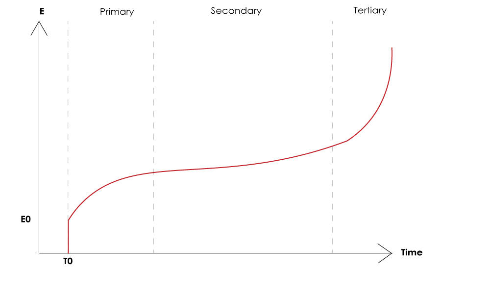
Data obtained in a creep test usually is presented as a plot of creep vs. time with stress and temperature constant. The slope of the curve is creep rate and the end point of the curve is time for rupture.

As indicated in the following diagram, the creep of a material can be divided into three stages.

  • Primary creep starts at a rapid rate and slows with time.
  • Secondary creep has a relatively uniform rate.
  • Tertiary creep has an accelerating creep rate and terminates by failure of material at time for rupture.

If failure occurs, the time for rupture is recorded. If a specimen does not fracture within the creep test period, creep recovery may be measured.

Example Plot of Creep Test

How to Perform a Creep Test

To determine creep properties, a material is subjected to prolonged constant tension or compression loading at a constant elevated temperature. These tests are typically performed on universal testing machines or dynamic testing machines, which are designed to apply controlled loads over extended periods.

While testing, the material's deformation is recorded at specific time intervals and the overall data is plotted on a creep vs. time diagram. The slope at any point on this curve is known as the creep rate, in which units are expressed in terms of in/in/hr or percent(%) elongation/hr.

Maintaining a constant temperature during a creep test is critical due to the possible thermal expansion or shrinkage of the material.

Some examples of standards that require creep testing are ASTM E139, ASTM D2290, ASTM D2291, and ASTM D2294. For more details on testing procedures, please refer to these standards.

How to Determine Stress-Relaxation

To determine the stress-relaxation of a material, the specimen is deformed a given amount and a decrease in stress is recorded over prolonged period of exposure at constant elevated temperature.

The stress-relaxation rate is the slope of the curve at any point.

Related Content

6800 Series Premier Testing Systems Brochure

Instron 6800 Series Universal Testing Systems provide unparalleled accuracy and reliability. Built on a patent-pending Operator Protect system architecture with an all-new Smart-Close Air Kit and Collision Mitigation features, the 6800 Series makes materials testing simpler, smarter, and safer than ever before.

3400 Series Universal Testing Systems Brochure

Instron 3400 Series universal testing systems for tensile, compression, bend, and other material property tests.

Bluehill Universal Brochure

Bluehill Universal is Instron’s advanced materials testing software, designed for intuitive touch interaction and streamlined workflows. It offers pre-loaded test methods, QuickTest for rapid setup, enhanced data exporting, and Instron Connect for direct service communication. Users of Bluehill 2 and Bluehill 3 can easily upgrade to the latest version for improved performance and usability.

Compression Set


Compression Set
»
Page 5


Compression Set

The extent to which rubber is permanently deformed by a prolonged compressive load (ASTM D-395). Should not be confused with low temperature compression set.

Related Content

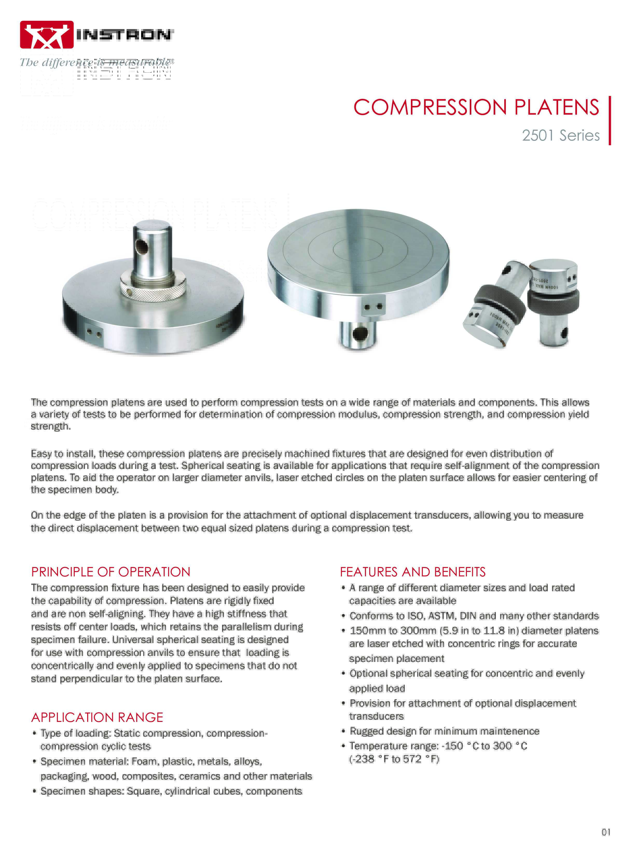
2501 Series Compression Platens

These easy-to-install compression platens are precisely machined fixtures that are designed for even distribution of compression loads during a test.

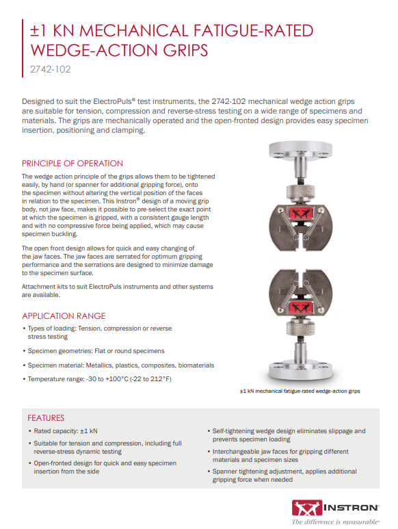
2742-102 MechanicalGrips

Designed to suit ElectroPuls test instruments, the 2742-102 mechanical wedge action grips are suitable for tension, compression and reverse-stress testing on a wide range of specimens and materials. The grips are mechanically operated and the open-fronted design provides easy specimen insertion, positioning and clamping.

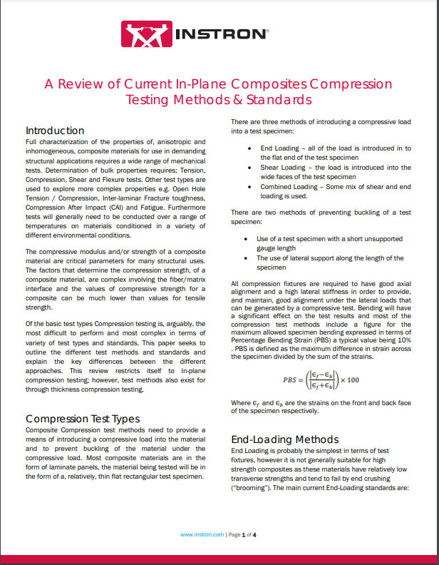
A Review of Current In-Plane Composites Compression Testing

The compressive modulus and/or strength of a composite material are critical parameters for many structural uses. The factors that determine the compression strength are complex and the values of compressive strength for a composite can be much lower than values for tensile strength. One of the challenges in the compression testing of composite laminates is in understanding the various test types and standards. This white paper seeks to document and explain this field.

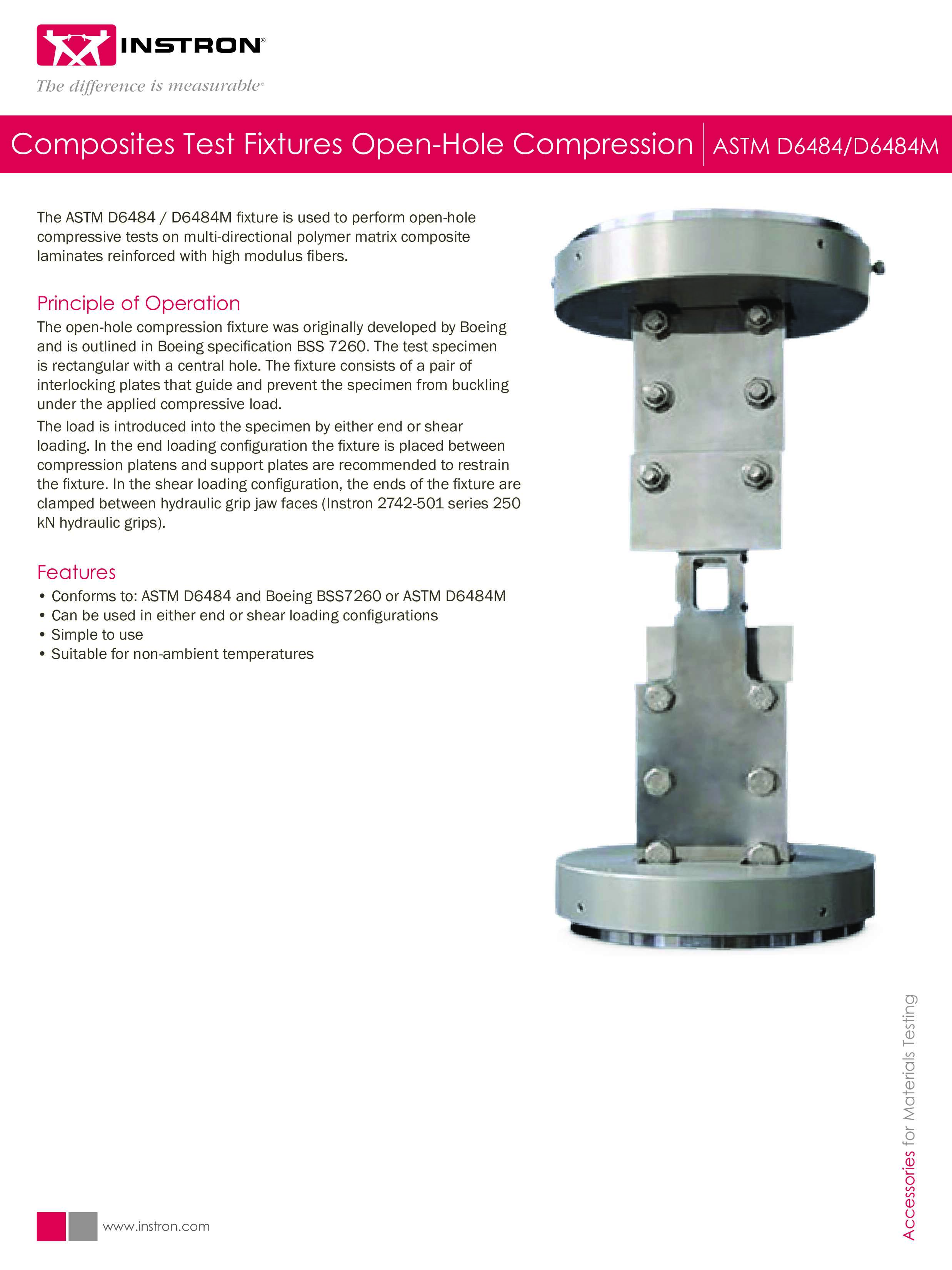
Composites Test Fixtures: Open Hole Compression

Composite Test Fixtures Open-Hole Compression testing is preformed on multi-directional polymer matrix composite laminates reinforced with high modulus fibers.

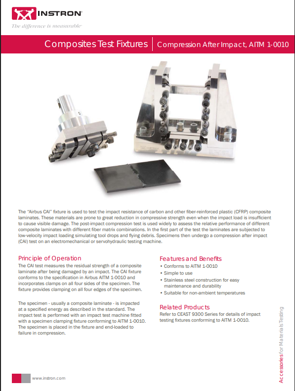
Composites Test Fixture Compression After Impact

The “Airbus CAI” fi xture is used to test the impact resistance of carbon and other fi ber-reinforced plastic (CFRP) composite laminates. These materials are prone to great reduction in compressive strength even when the impact load is insuffi cient to cause visible damage. The post-impact compression test is used widely to assess the relative performance of different composite laminates with different fi ber matrix combinations. In the fi rst part of the test the laminates are subjected to low-velocity impact loading simulating tool drops and fl ying debris. Specimens then undergo a compression after impact(CAI) test on an electromechanical or servohydraulic testing machine.

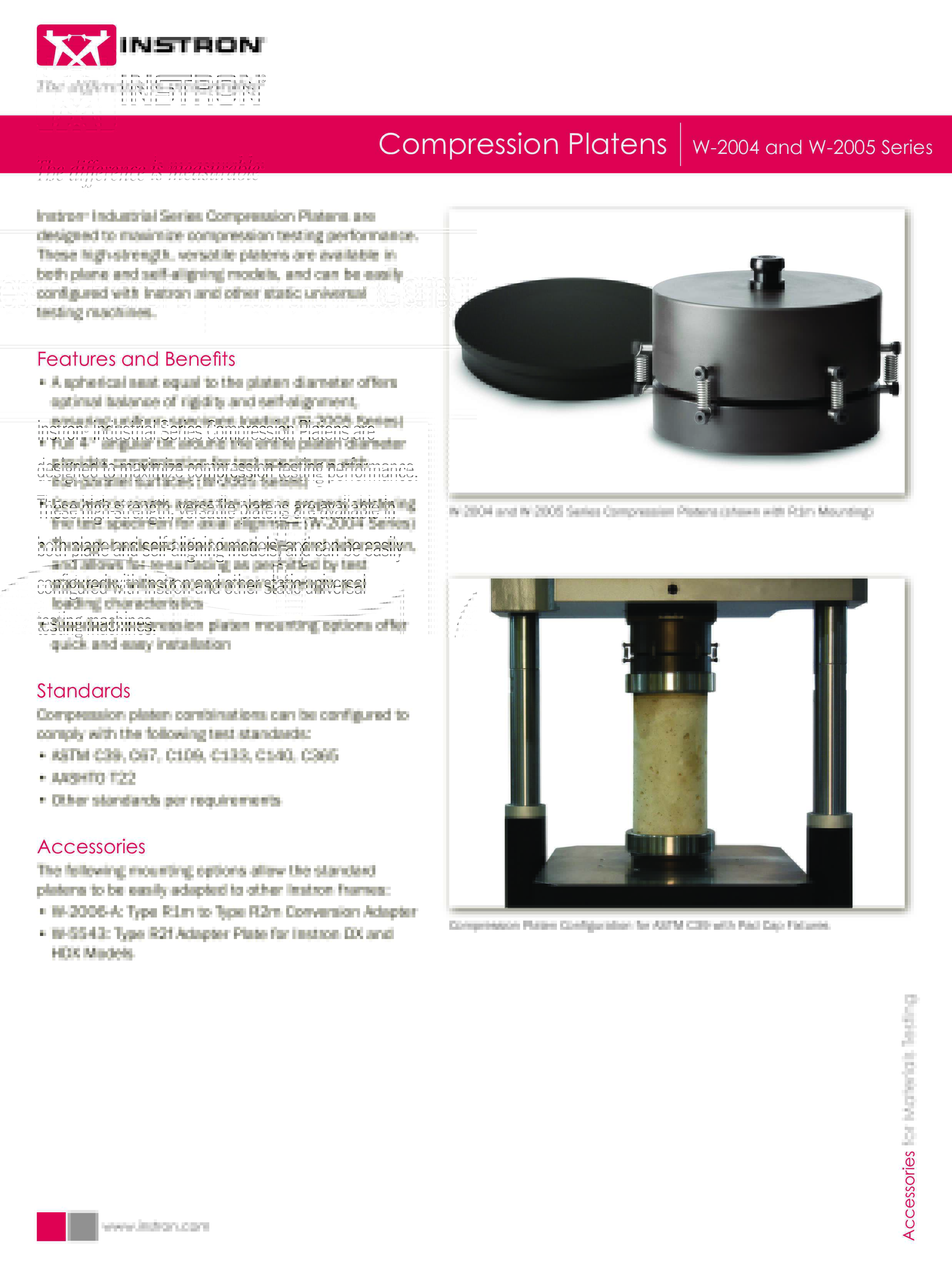
Compression Platens W-2004 and W-2005 Series

Instron® Industrial Series Compression Platens are designed to maximize compression testing performance. These high-strength, versatile platens are available in both plane and self-aligning models, and can be easily configured with Instron and other static universal testing machines.

Anti-Buckling Compression Testing Fixture

This anti-buckling fixture is designed for compression testing of rigid plastics and the shear testing of reinforced plastics. It has also been adapted for use with high strength composites.

Ball Burst Compression Fixture

Burst or puncture fixtures are used to determine the resistance of a material to the penetration of a probe.

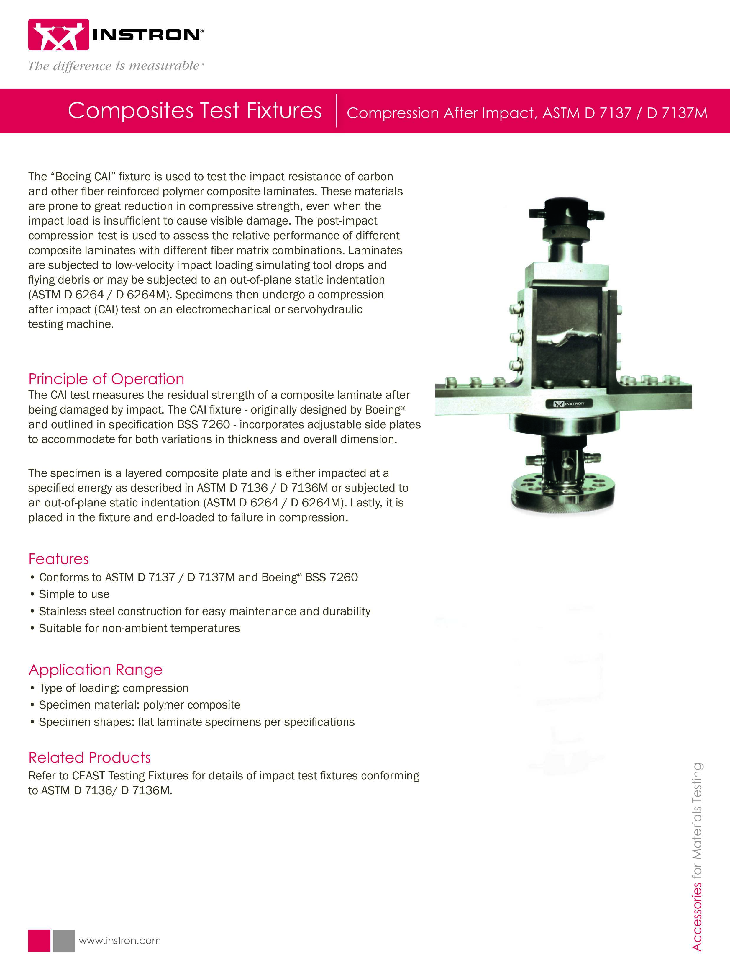
Composite Test Fixtures_Compression After Impact, ASTM D 7137 / D 7137M

The “Boeing CAI” fixture is used to test the impact resistance of carbon and other fiber-reinforced polymer composite laminates. These materials are prone to great reduction in compressive strength, even when the impact load is insufficient to cause visible damage. The post-impact compression test is used to assess the relative performance of different composite laminates with different fiber matrix combinations. Laminates are subjected to low-velocity impact loading simulating tool drops and flying debris or may be subjected to an out-of-plane static indentation (ASTM D 6264 / D 6264M). Specimens then undergo a compression after impact (CAI) test on an electromechanical or servohydraulic testing machine.

CEAST: Compagnia Europea Apparecchi Scientifici Torino (CEAST)

CEAST: Compagnia Europea Apparecchi Scientifici Torino (CEAST)

CEAST stands for Compagnia Europea Apparecchi Scientifici, Torino.  This is an Italian phrase meaning a European Scientific Instruments Company located in Torino.

From the acronym, you may have guessed that CEAST was founded in Italy.  However, today it is no longer just a European company. CEAST was acquired by Illinois Tool Works (ITW) in 2008 and has been positioned under its Test & Measurement Group’s Instron Division.

Today the CEAST product lines are sold around the world through Instron's sales & service team as well as a local agencies.

The company was originally founded in 1953 by Dr. Mario Grosso. CEAST supplied instruments for the Italian Petrochemical Industry that had been destroyed by the World War II. CEAST starting then to develop instruments for polymers characterization, research and quality control, collaborating with Dr. Giulio Natta (Nobel Prize winner for the first synthesis of Polypropylene). CEAST was known for supplying advanced testing equipment for mechanical, physical and rheological characterization of all polymer types with the first Melt Flow instrument in 1960.

Today, CEAST products are still designed and manufactured in Italy.

Related Content

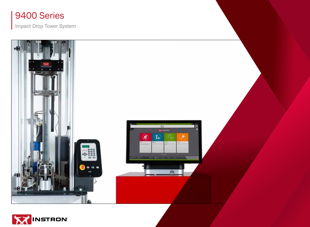
9400 Series Drop Tower Brochure

Instron Drop Towers are used to develop, fine tune, and validate material models. Testing materials under real impact conditions is a crucial step prior of product design. Using the characterization data obtained with the Instron 9400, coupled with customer supplied high-speed video, you can have confidence in your results and deliver new materials to your customers faster. Our Drop Tower impact systems, fixtures, and tups are designed to meet a wide range of applications and testing standards including: ISO, ASTM, ANSI, Airbus, Boeing, BSI, DIN, EN, FDA, Ford, GM, JIS, NASA, GOST, and more.

9000 Series Pendulum Impact Testers POD

The Instron 9000 Series of pendulum impact testers are designed for determining the impact resilience of thermoplastics. Available in capacities from 0,5 to 50 Joules, the 9050 models are reliable and easy to operate.

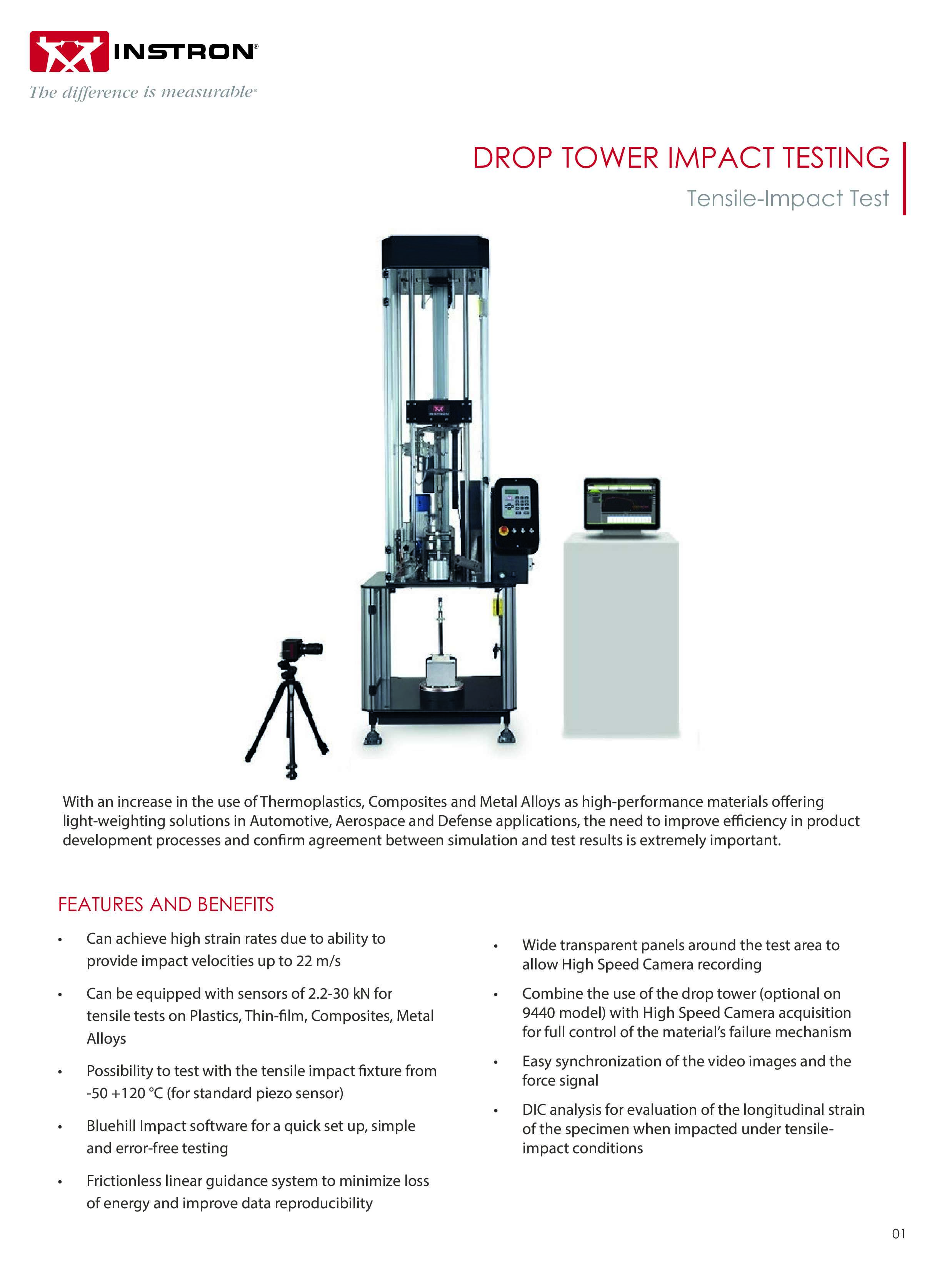
Drop Tower Tensile Impact Testing

With an increase in the use of Thermoplastics, Composites and Metal Alloys as high-performance materials offering light-weighting solutions in Automotive, Aerospace and Defense applications, the need to improve efficiency in product development processes and confirm agreement between simulation and test results is extremely important.

Motorized Impact Testing System (MPX)

The Instron® MPX Series of motorized pendulum impact testers are preferred for metals impact testing to Charpy and Izod standards.

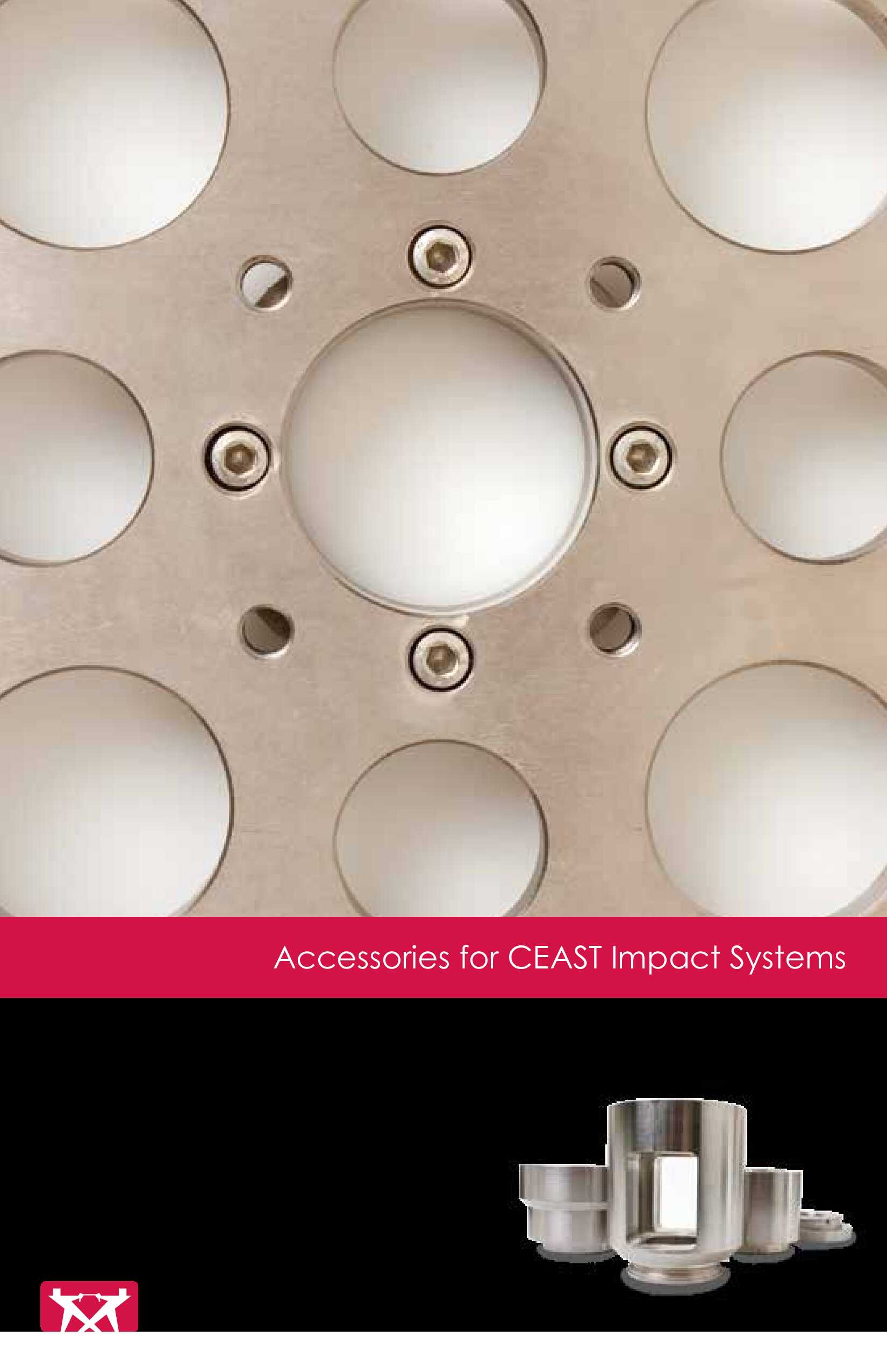
Accessories for CEAST Impact Systems

Accessories for CEAST Drop Tower and Pendulum Impact Testers.

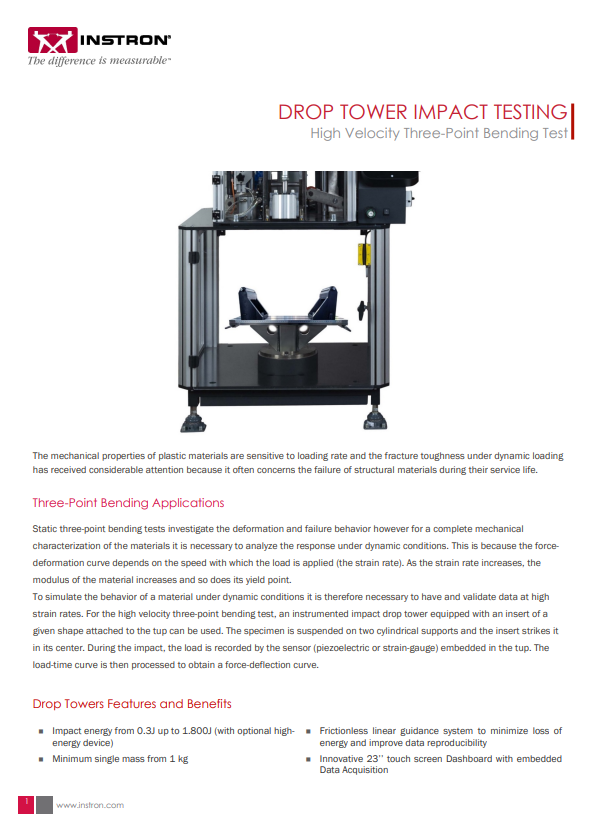
Impact Drop Tower – Three-Point Bending

The mechanical properties of plastic materials are sensitive to loading rate and the fracture toughness under dynamic loading has received considerable attention because it often concerns the failure of structural materials during their service life.

Capillary Rheometer

Capillary Rheometer

A capillary rheometer is an apparatus designed to measure shear viscosity and other rheological (= flow) properties. Capillary rheometers for plastics are piston-die systems designed to measure viscosity of polymer melts as a function of temperature and rate of deformation. They are capable of testing basic polymers, compounds, various composites with small reinforcing particles or fibers, feedstock for metal injection molding and similar materials.

The basic principle is that a thermoplastic sample (originally in the shape of granules, powder or flakes) is made fluid by heating and forced to flow out of a cylinder through a capillary die. The measured quantity is normally the generated pressure under steady state conditions. A flow curve is the typical output, obtained by interpolation of several experimental data. Viscosity is represented as the Greek letter “eta” (η) and expressed (in SI units) in pascal seconds (Pa·s) or newton seconds per square meter (N·s/m2).

Capillary rheometers ensure testing conditions which are truly representative of processing conditions, especially for high-pressure and high-speed techniques like injection molding, therefore they are key for process optimization.

Other rheological properties that can be measured or estimated from capillary rheometers data include extensional viscosity, extrudate swell, thermal stability, wall slip. Ancillary measurements can be carried out for thermal conductivity, density dependence on pressure and temperature (pvT), melt strength.

References

  • Walters K. “Rheometry”, Chapman & Hall (1975)
  • Ferry, J. D. “Viscoelastic Properties of Polymers”, John Wiley & Sons (1980)
  • Dealy, J.M. and Wissbrun K.F. “Melt Rheology and its Role in Plastics Processing”, Van Nostrand Reinhold (1990), Chapman & Hall (1995)
  • Macosko C.W. “Rheology – Principles, Measurements, and Applications”, Wiley-VCH (1994)
  • Malkin A.Y. “Rheology – Concepts, Methods, & Applications”, ChemTec Publishing (2006)

Related Content

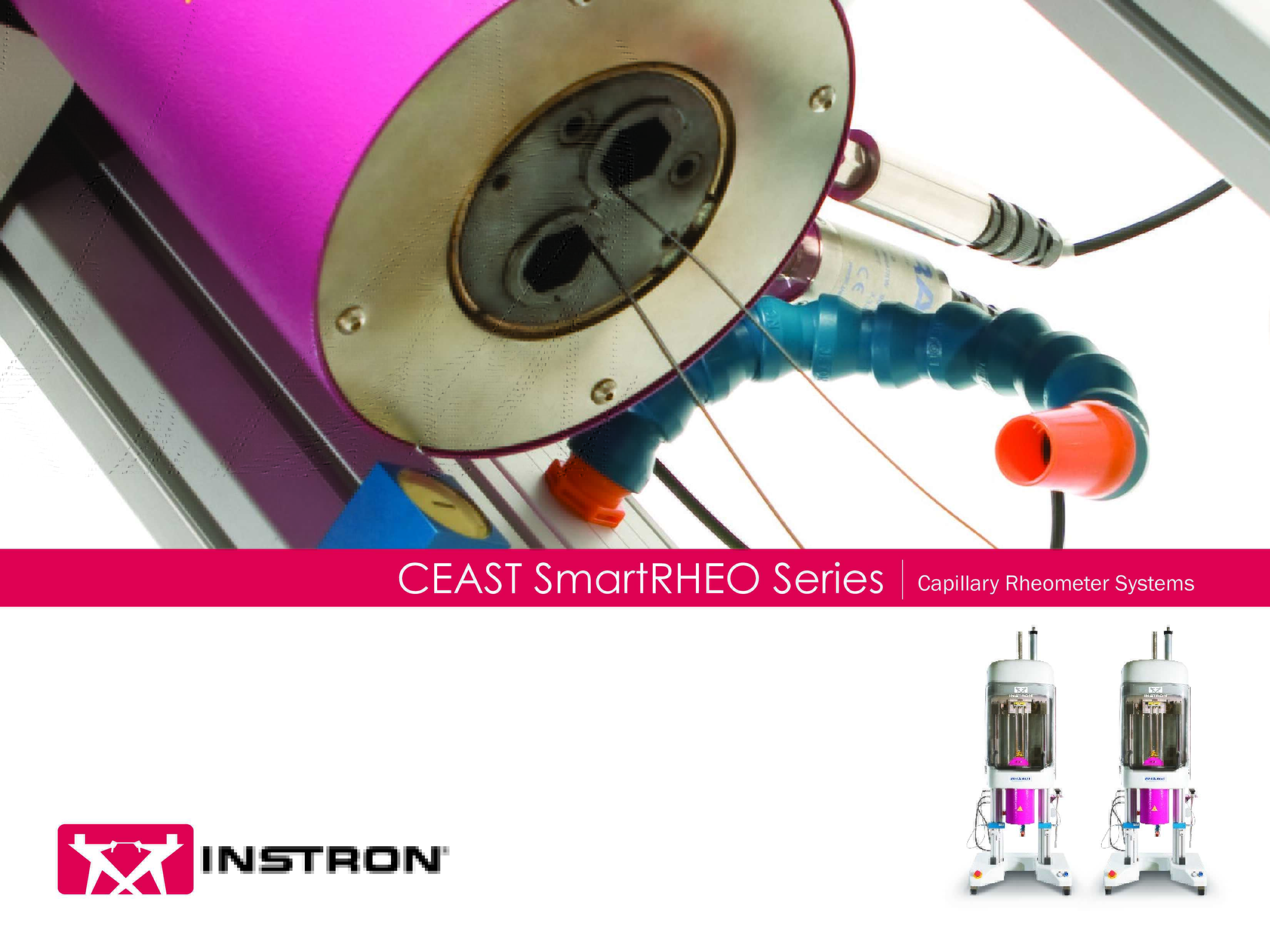
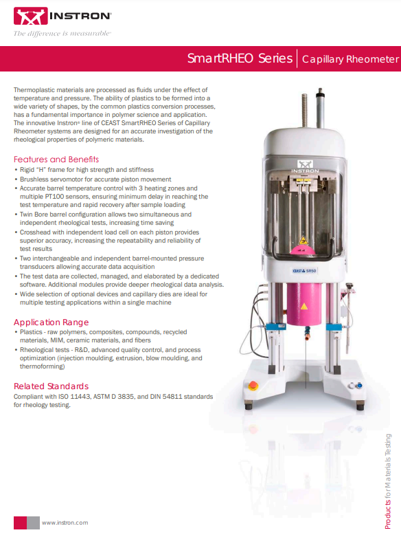
CEAST SmartRHEO Series: Capillary Rheometer Systems

Thermoplastic materials are processed as fluids under the effect of temperature and pressure. The ability of plastics to be formed into a wide variety of shapes, by the common plastics conversion processes, has a fundamental importance in polymer science and application. The innovative Instron® line of CEAST SmartRHEO Series of Capillary Rheometer systems are designed for an accurate investigation of the rheological properties of polymeric materials.

Capillary Rheometer Systems

The innovative Instron® line of CEAST SmartRHEO Series of Capillary Rheometer systems are designed for an accurate investigation of the rheological properties of polymeric materials.

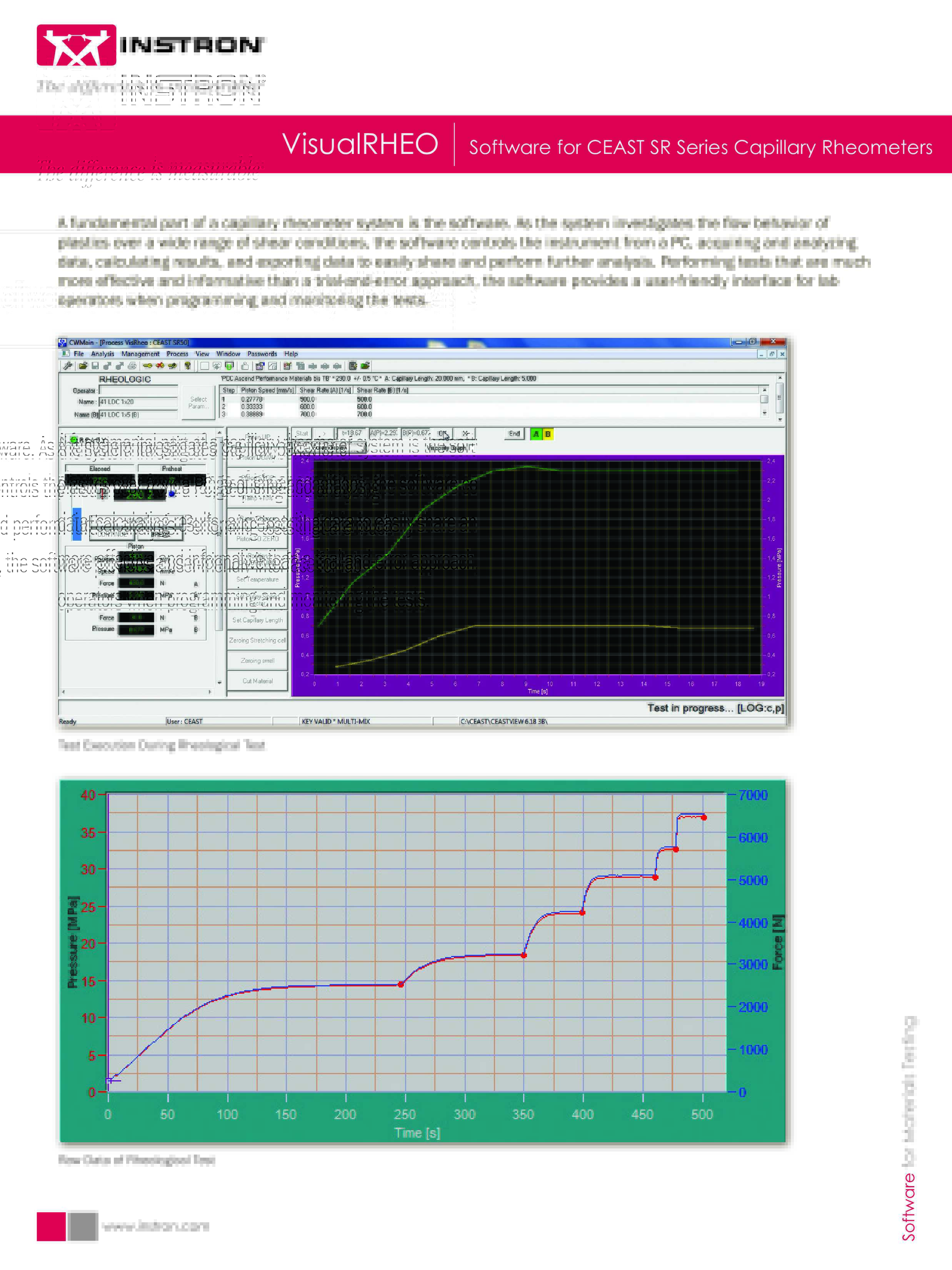
VisualRHEO | Software for CEAST SR Series Capillary Rheometers

A fundamental part of a capillary rheometer system is the software. As the system investigates the flow behavior of
plastics over a wide range of shear conditions, the software controls the instrument from a PC, acquiring and analyzing
data, calculating results, and exporting data to easily share and perform further analysis. Performing tests that are much
more effective and informative than a trial-and-error approach, the software provides a user-friendly interface for lab
operators when programming and monitoring the tests.

Calibration

Calibration » Page 5

Calibration

Calibration is the process of comparing an unknown value to a known value. To calibrate a device is to compare a characteristic of that device with the characteristic of a similar device called a “standard.” Using load cells as an example, the load cell being calibrated and the standard load cell are mounted together in series and a range of loads is applied. Both load cells experience the same load and therefore the output values should ideally be identical. A calibration result most often indicates a difference between the two values.

A common misconception is that calibration means adjusting the output of a device to bring its performance “within limits.” Any adjustment made to the output of the device is separate from the calibration and verification process, and must be followed by a further calibration and verification to prove the adjustment was successful.

NOTE: It is important not to confuse CALIBRATION with the term "calibrate" that is sometimes used on instruments to refer to the actions of setting up a transducer such as a loadcell or extensometer to work with the system.

Below are the definitions as defined by the International Vocabulary of Metrology.

2.39 (6.11) calibration
Operation that, under specified conditions, in a first step, establishes a relation between the quantity values with measurement uncertainties provided by measurement standards and corresponding indications with associated measurement uncertainties and, in a second step, uses this information to establish a relation for obtaining a measurement result from an indication

NOTE 1: A calibration may be expressed by a statement, calibration function, calibration diagram, calibration curve, or calibration table. In some cases, it may consist of an additive or multiplicative correction of the indication with associated measurement uncertainty.

NOTE 2: Calibration should not be confused with adjustment of a measuring system, often mistakenly called "self-calibration," nor with verification of calibration.

Related Content

Alignment Test | Instron Professional Services

Instron Field Service and Calibration Engineers have developed and established materials testing alignment services complying with the guidelines and calculations detailed within ASTM E1012 and Nadcap standards.

3400 Series Universal Testing Systems Brochure

Instron 3400 Series universal testing systems for tensile, compression, bend, and other material property tests.

6800 Series Premier Testing Systems Brochure

Instron 6800 Series Universal Testing Systems provide unparalleled accuracy and reliability. Built on a patent-pending Operator Protect system architecture with an all-new Smart-Close Air Kit and Collision Mitigation features, the 6800 Series makes materials testing simpler, smarter, and safer than ever before.

Bluehill Universal Brochure

Bluehill Universal is Instron’s advanced materials testing software, designed for intuitive touch interaction and streamlined workflows. It offers pre-loaded test methods, QuickTest for rapid setup, enhanced data exporting, and Instron Connect for direct service communication. Users of Bluehill 2 and Bluehill 3 can easily upgrade to the latest version for improved performance and usability.