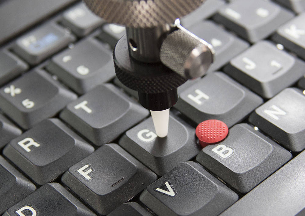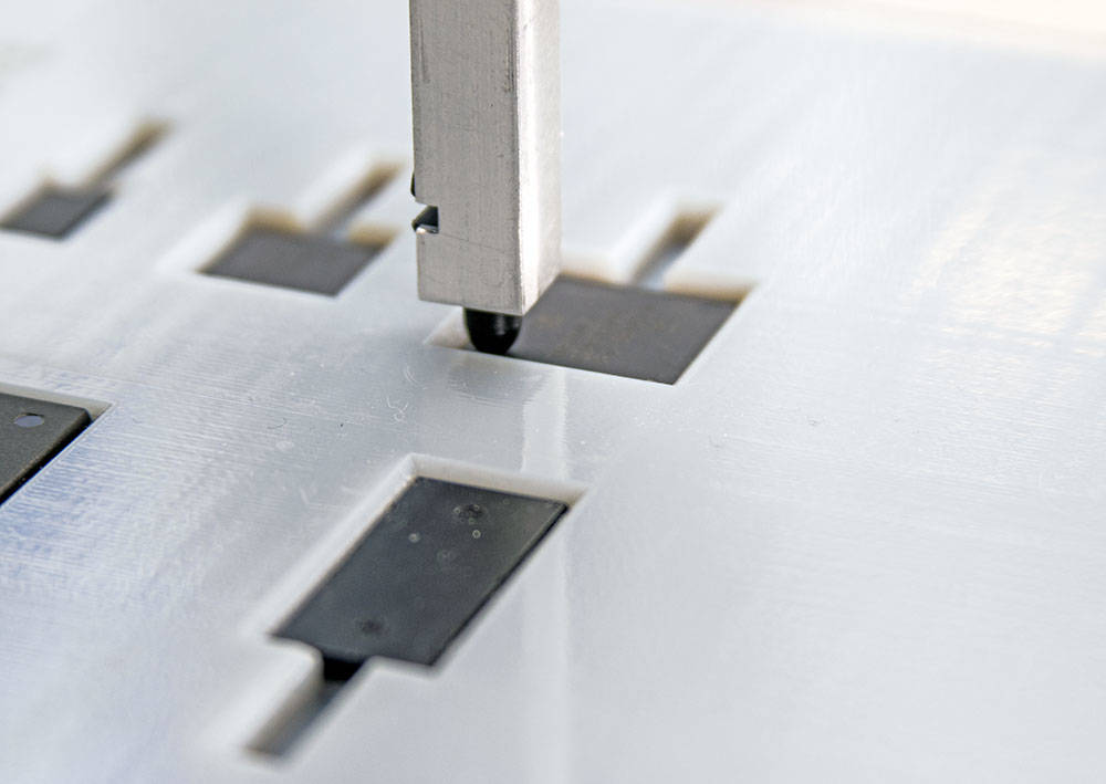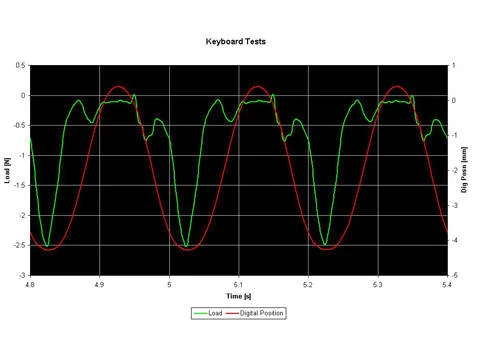

핸드폰의 소형화는 전화를 걸거나 데이터를 입력시키기 위한 버튼 역시 소형화된다는 의미입니다. 이러한 키패드들은 사용하기에 충분히 쉬운지가 시험되어야 합니다. 이러한 성능의 한 평가방법은 키패드의 작동에 필요한 힘의 측정과 개개 버튼의 동작형태입니다. 버튼을 작동시키는데 필요한 힘은 쉽게 눌러 동작이 되도록 충분히 작은 힘이어야 합니다. 그러나 주머니나 가방에 넣어 두었을 때 뜻하지 않게 작동되지는 않을 정도로 너무 낮은 낮은 힘에 의해 작동되어서도 안됩니다.
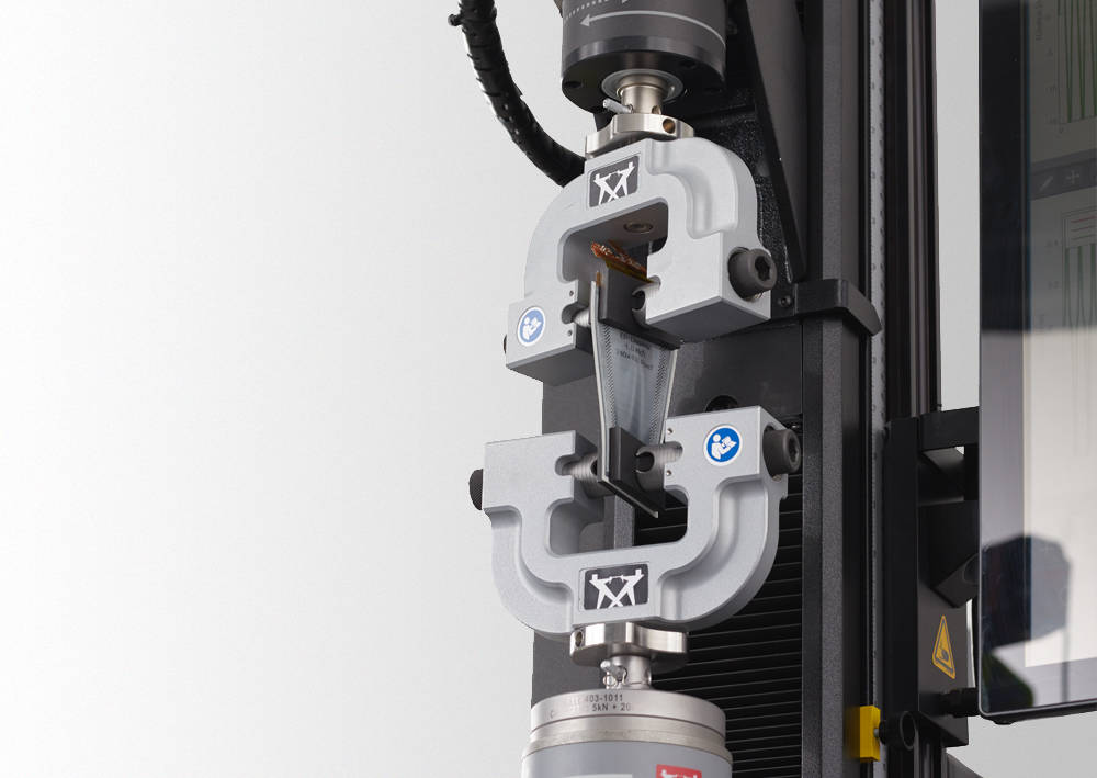
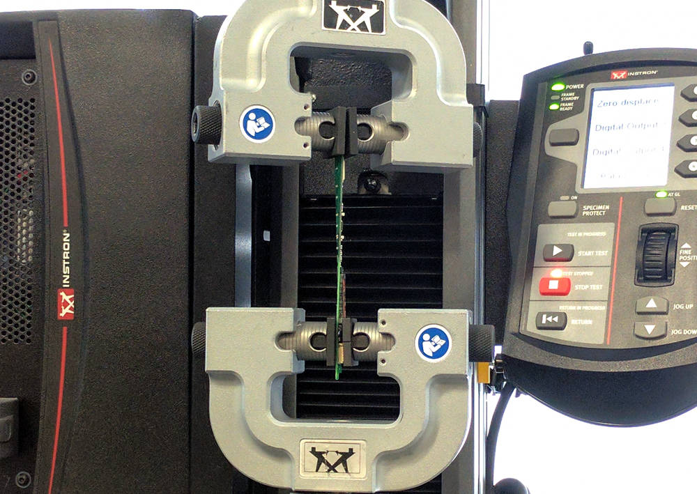
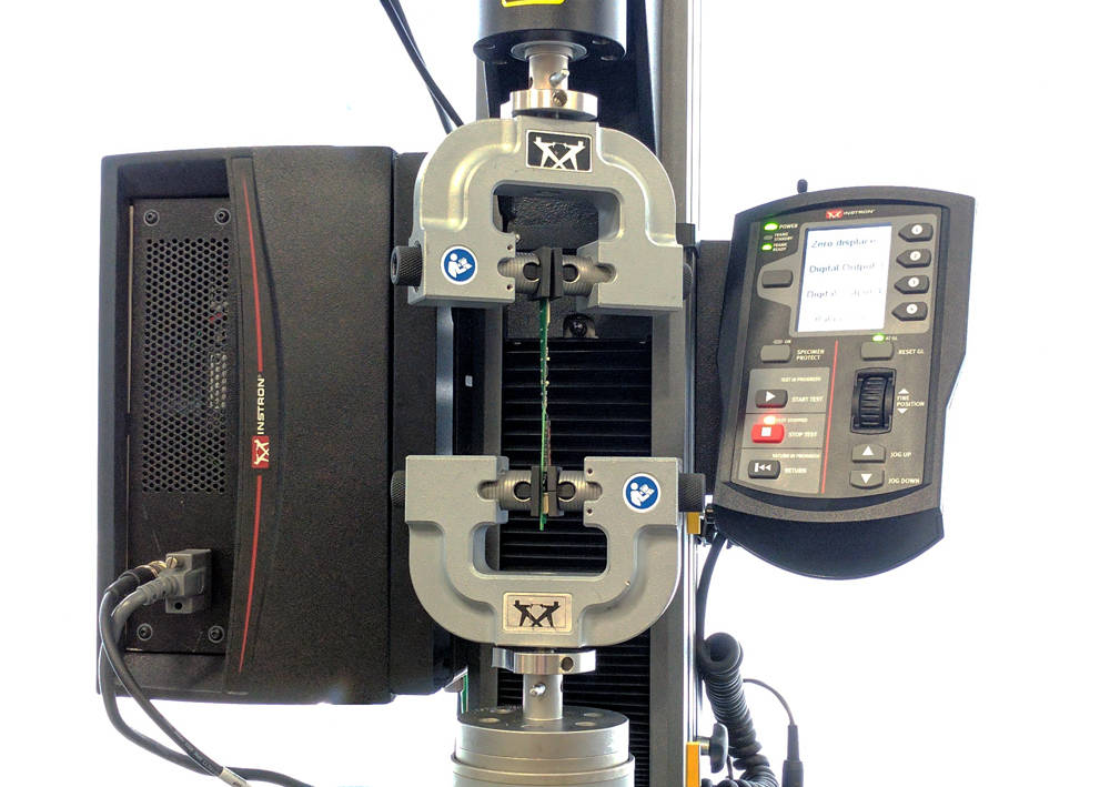
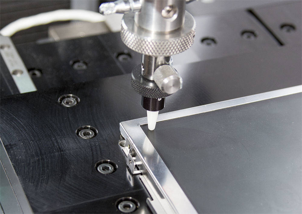
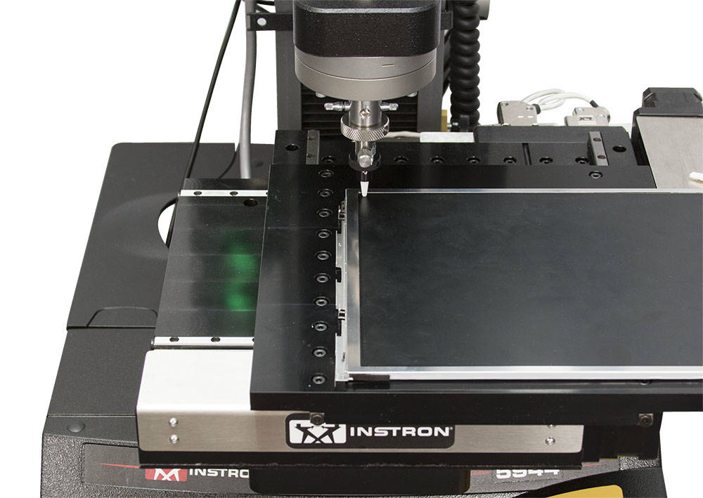
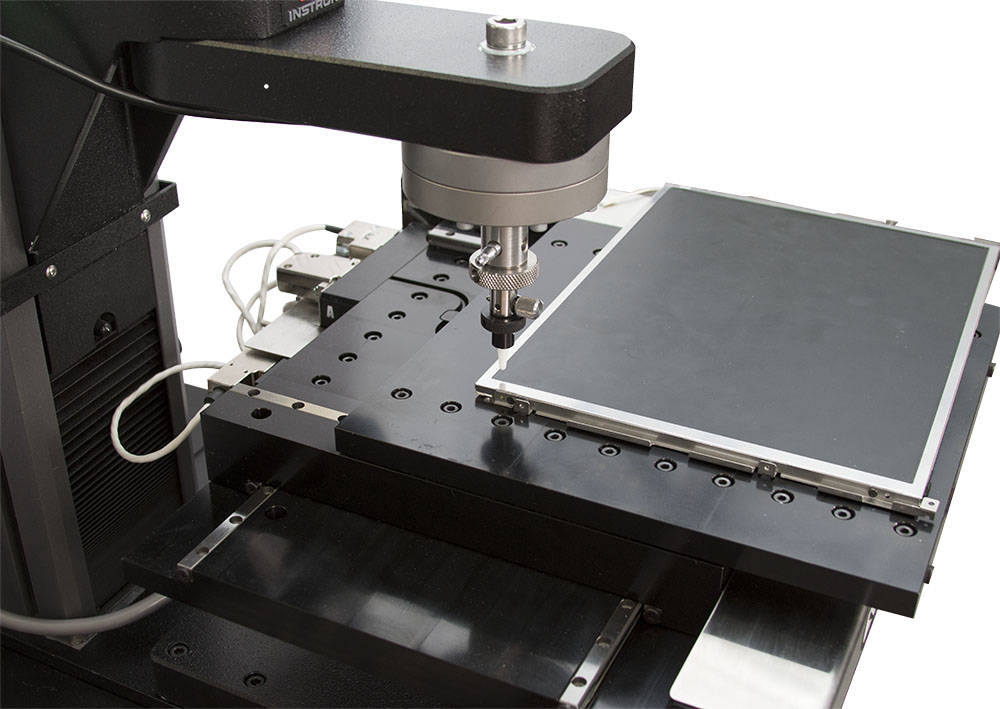
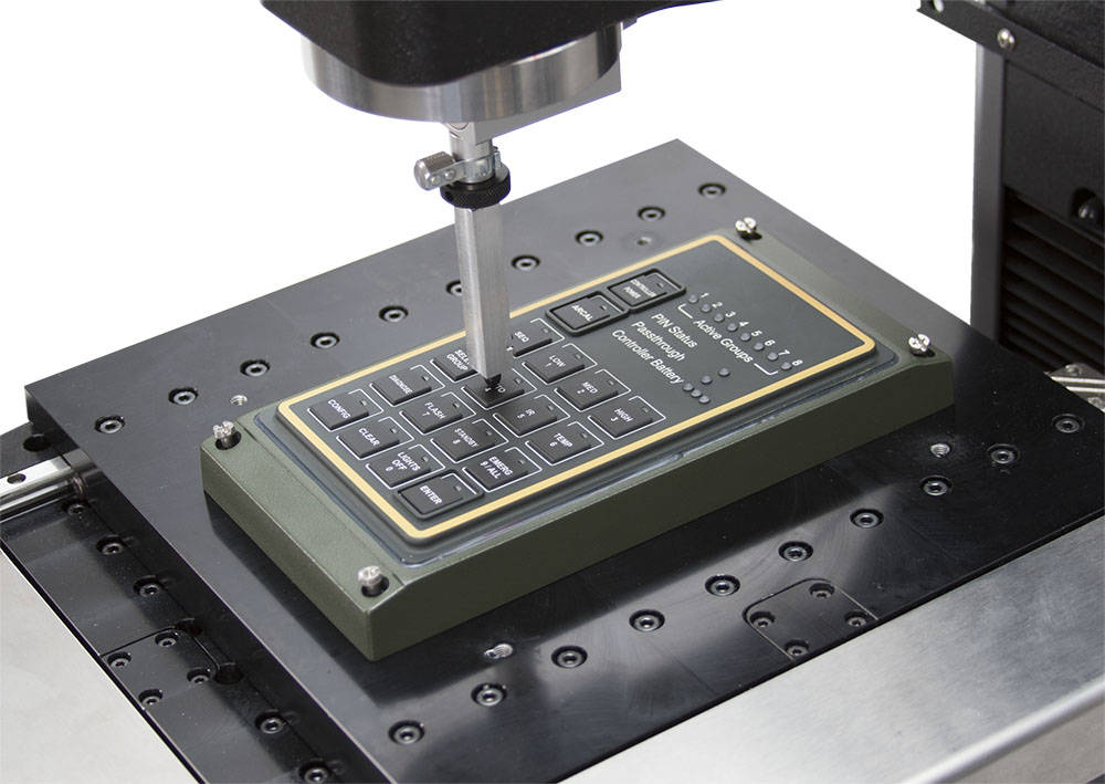
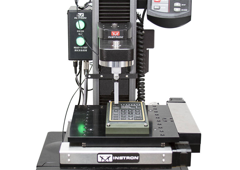
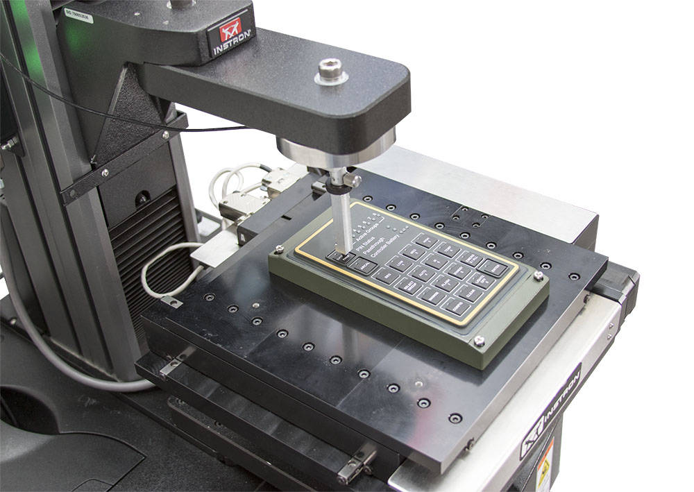
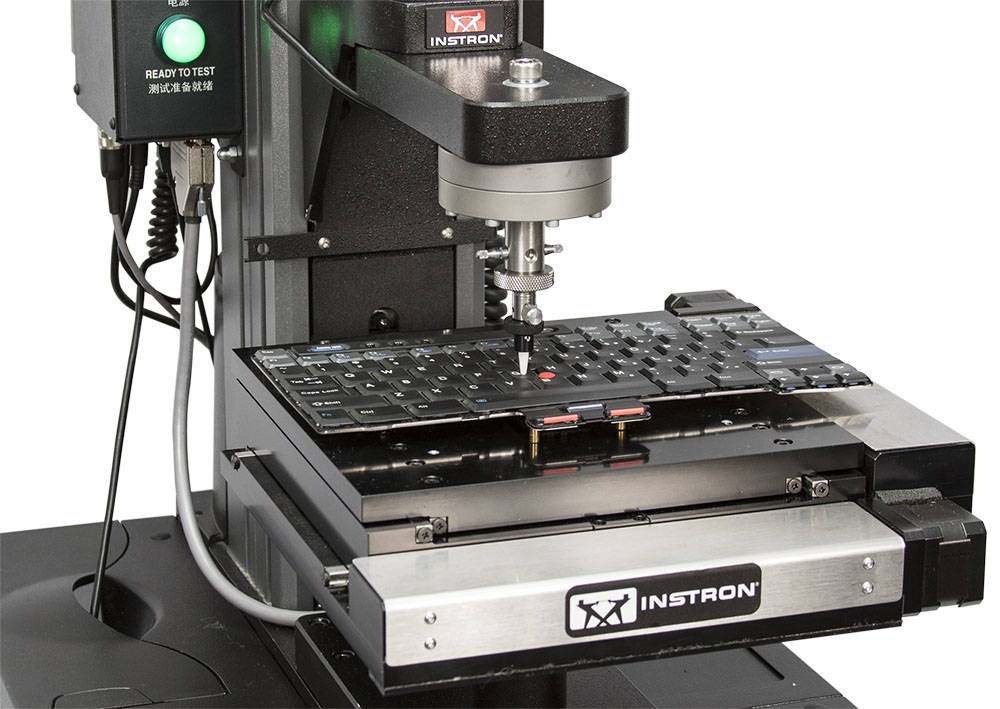
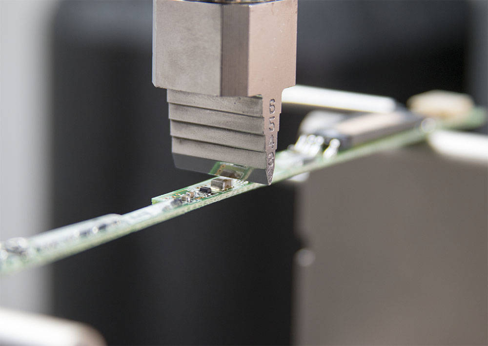
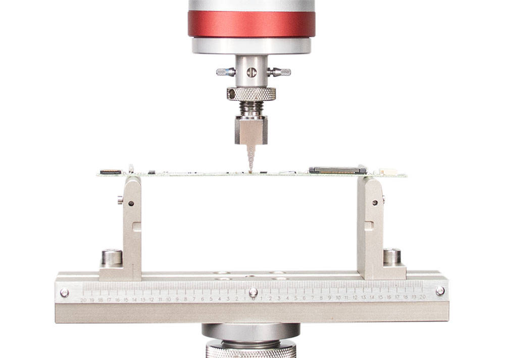
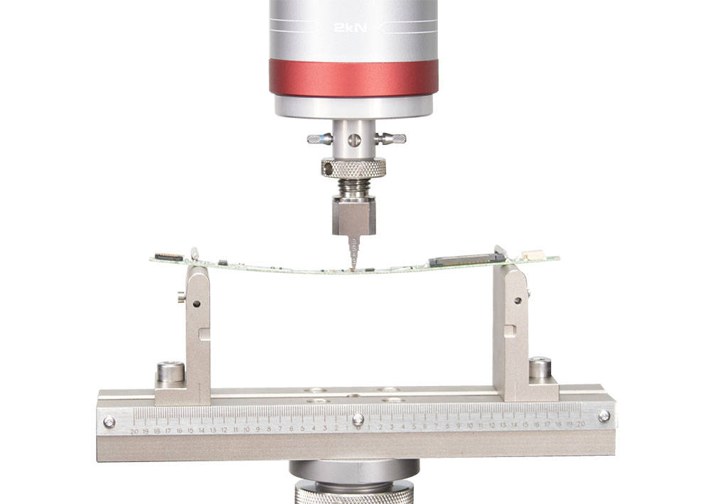
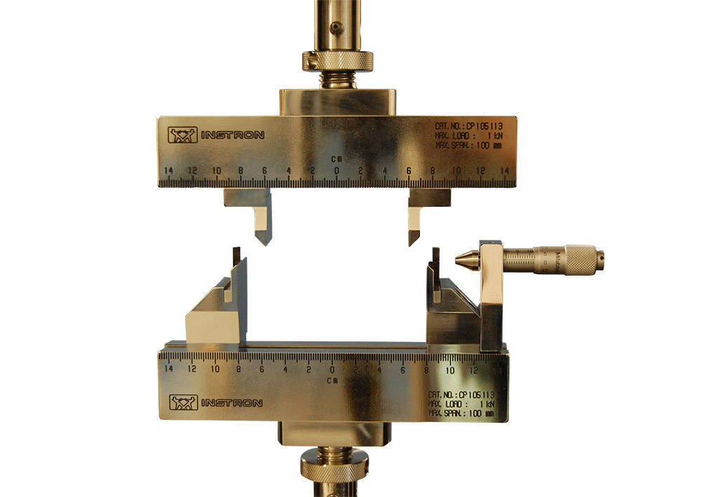
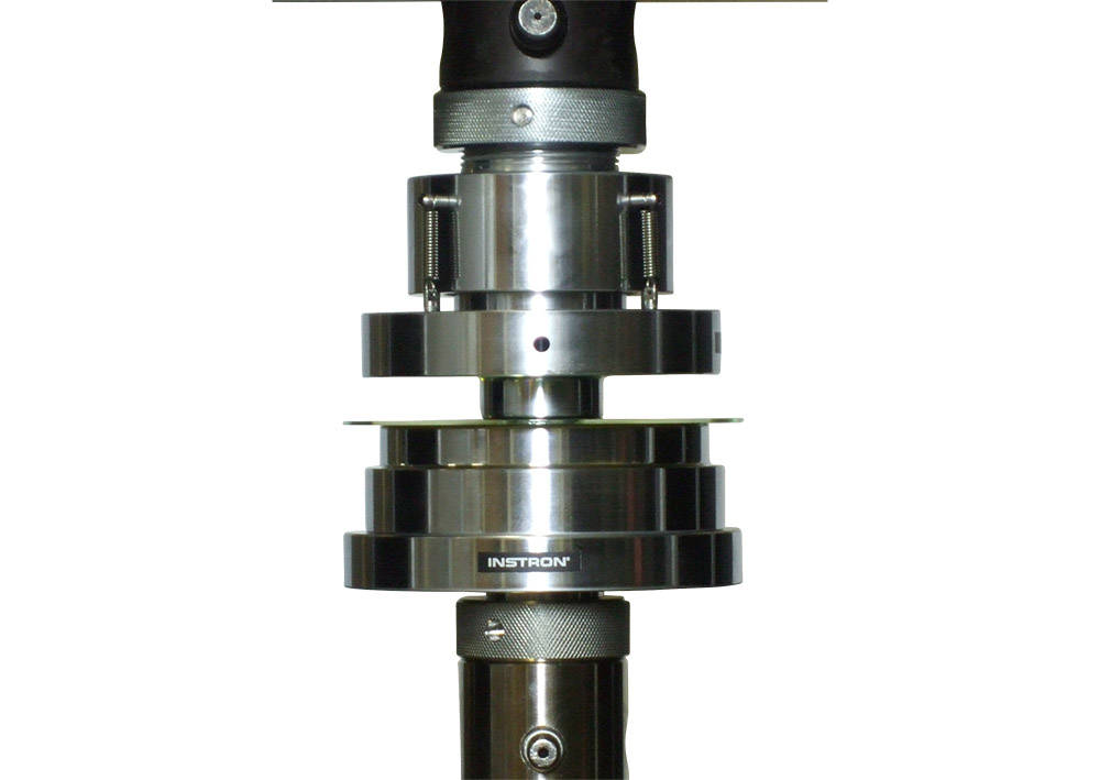
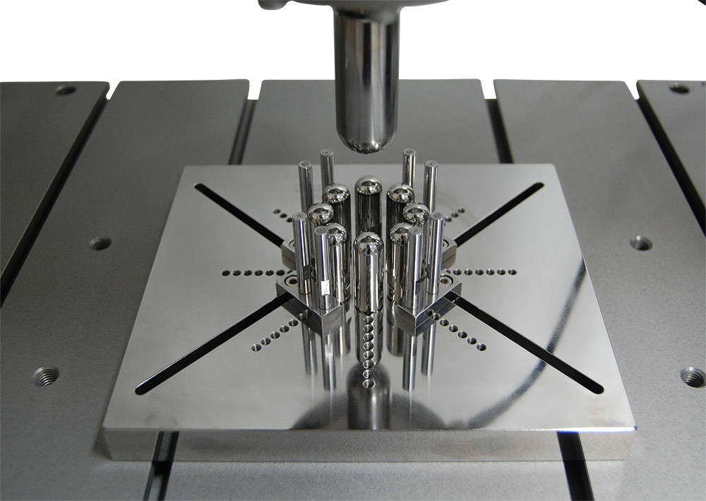
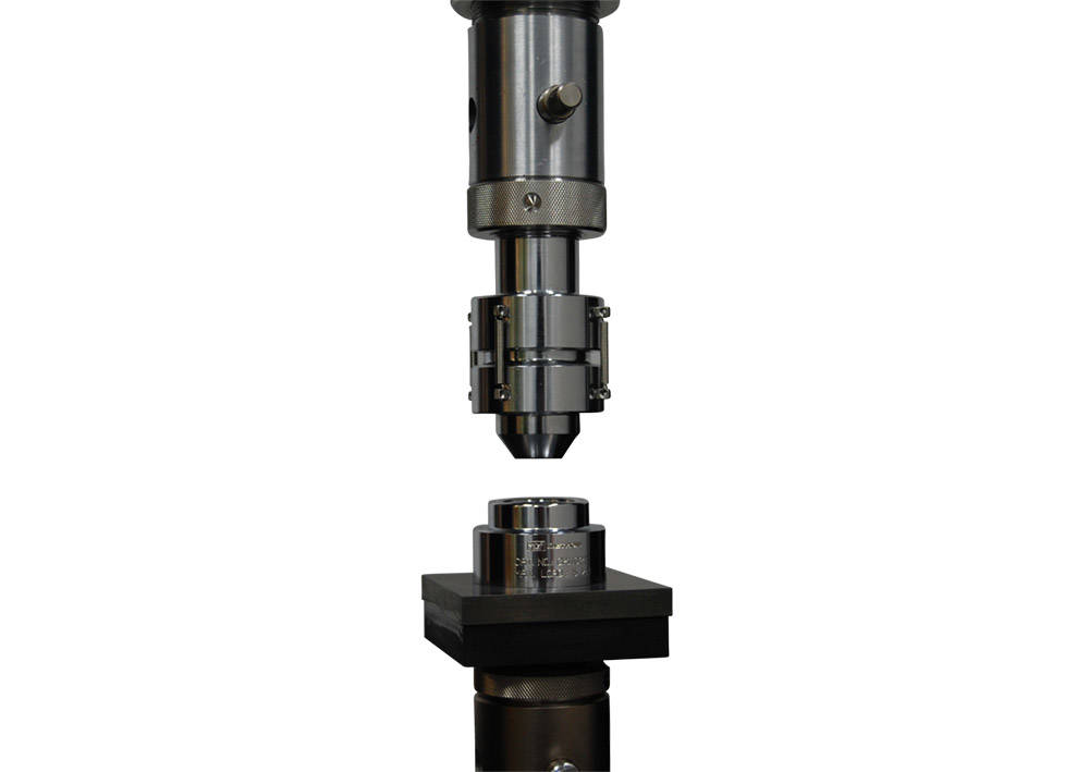
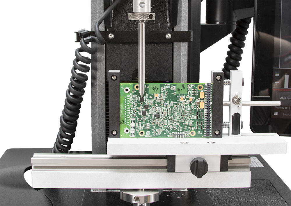
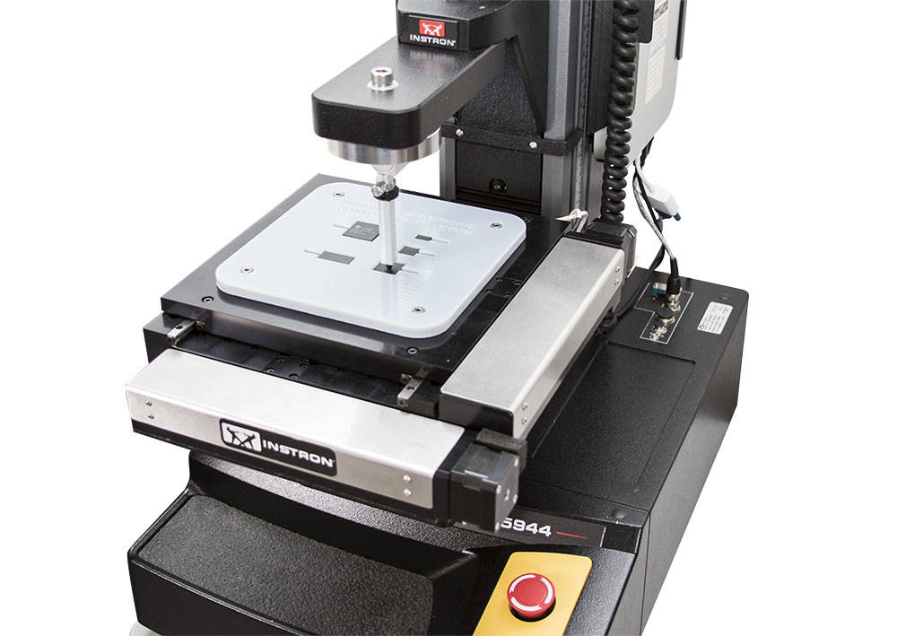
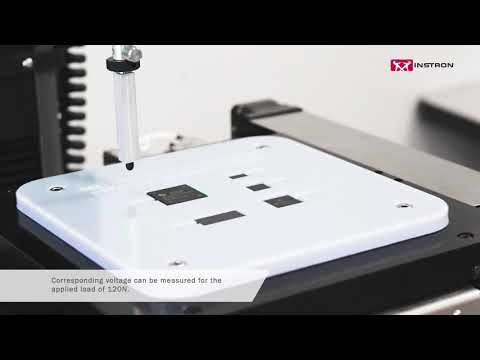
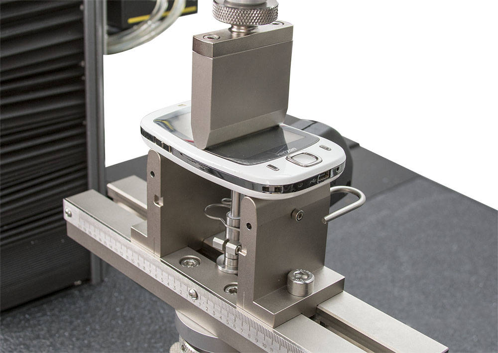
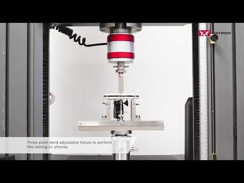
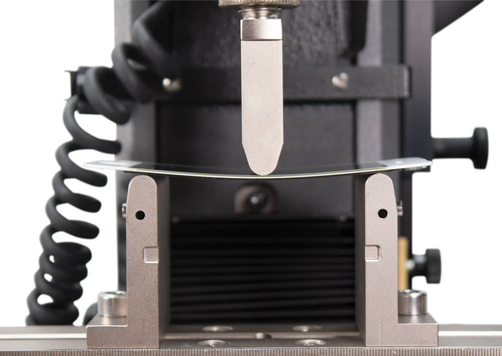
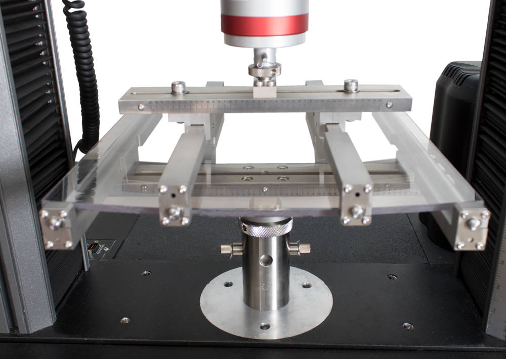
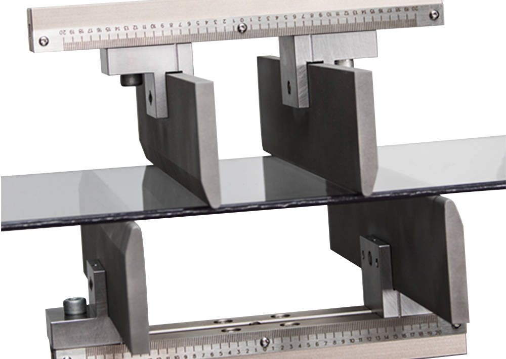
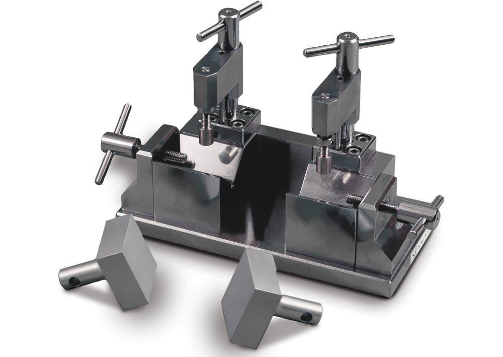
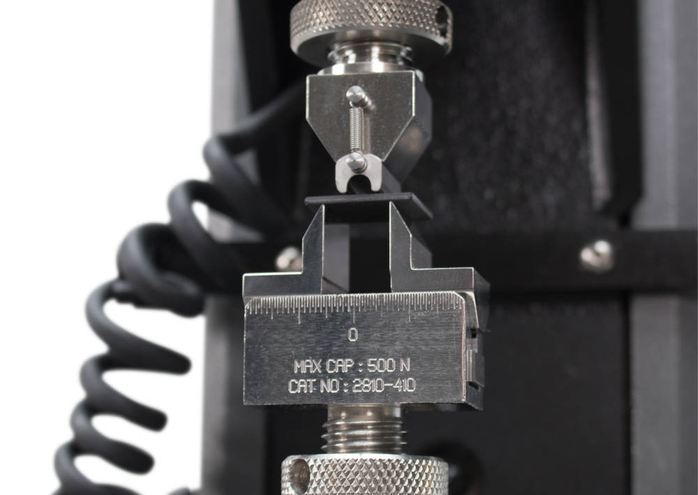
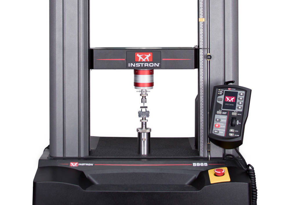
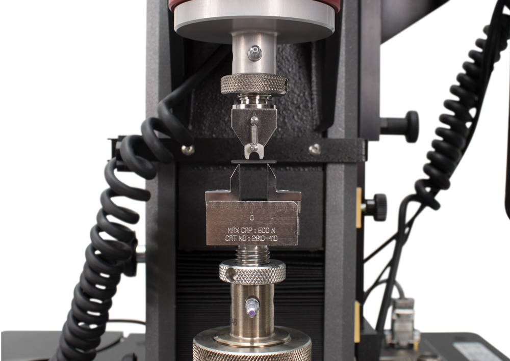
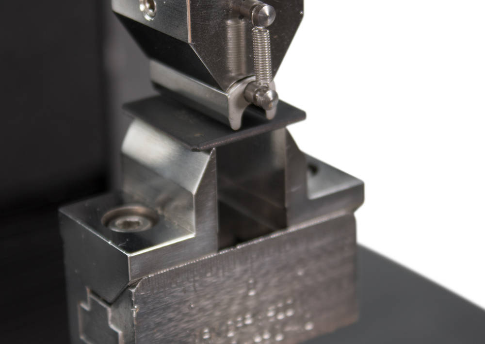
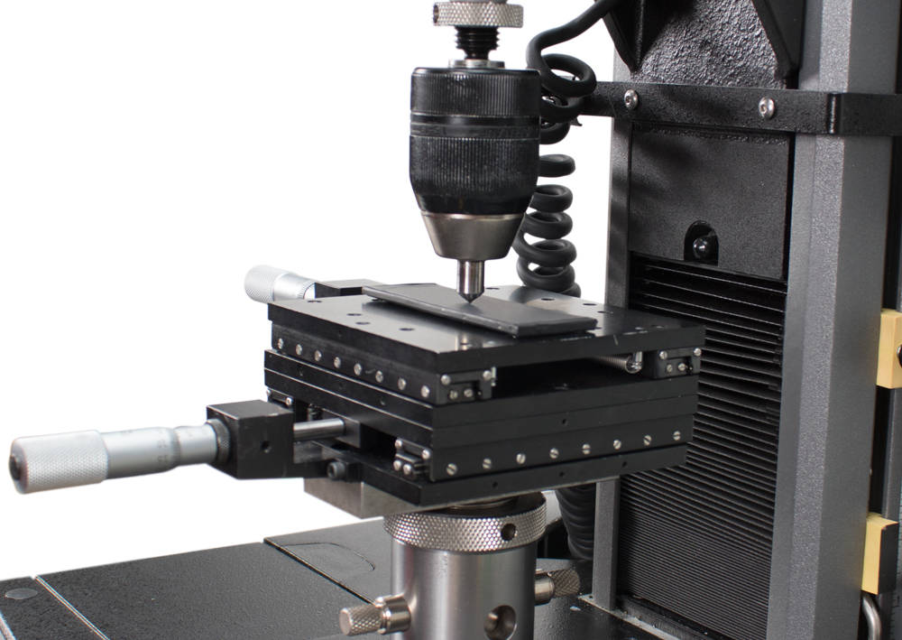
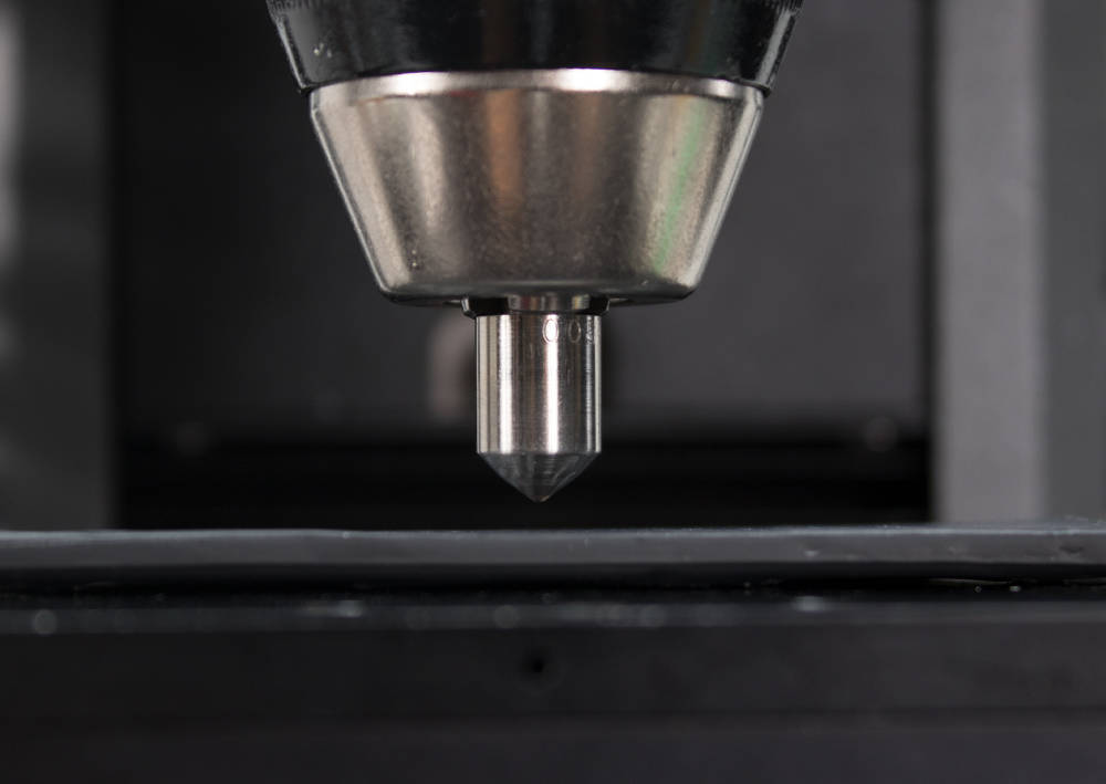
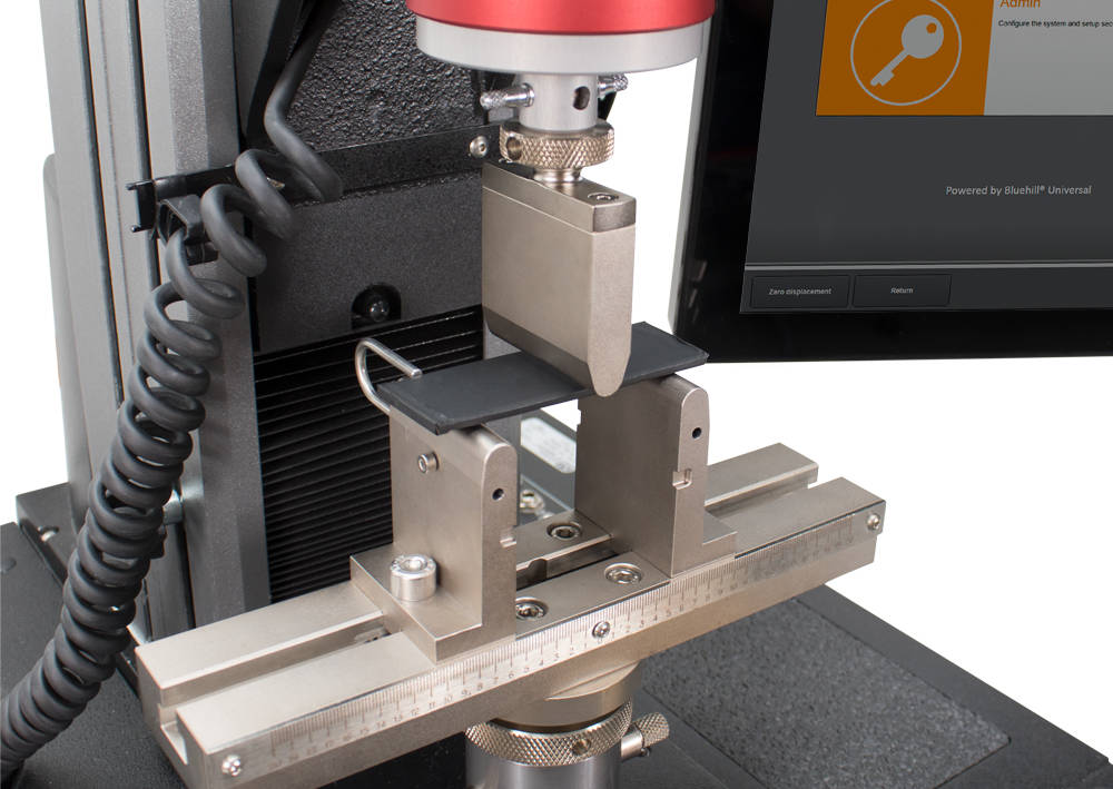
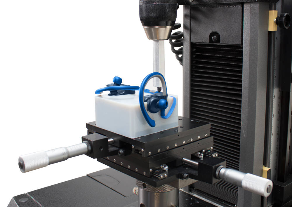
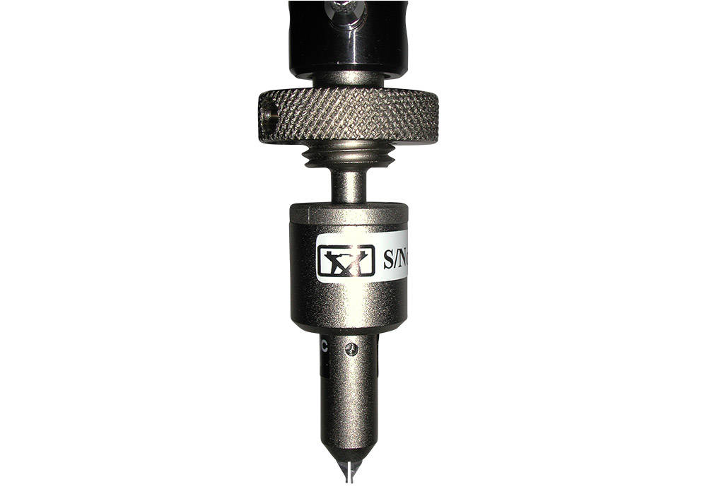
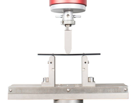
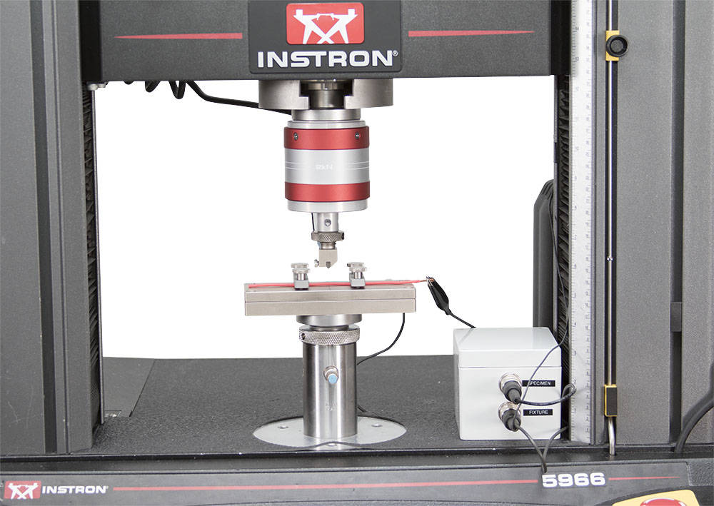
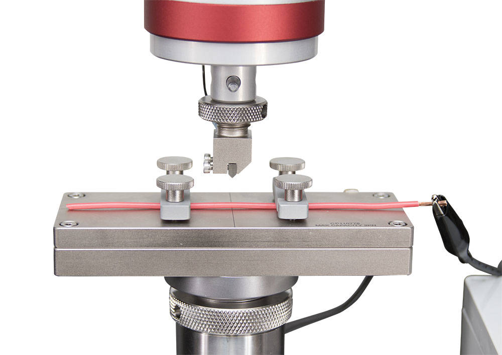
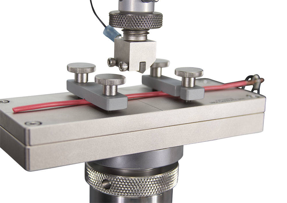
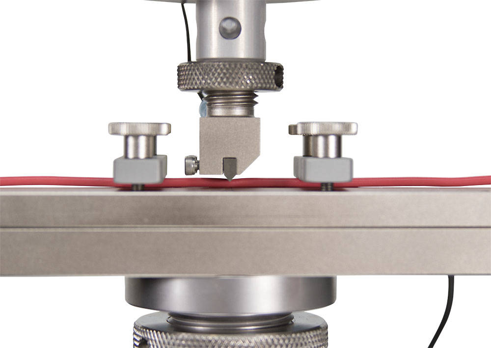
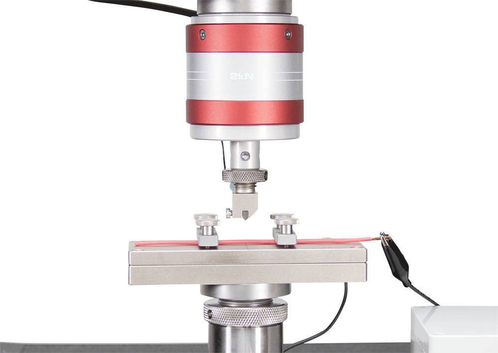
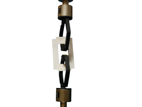
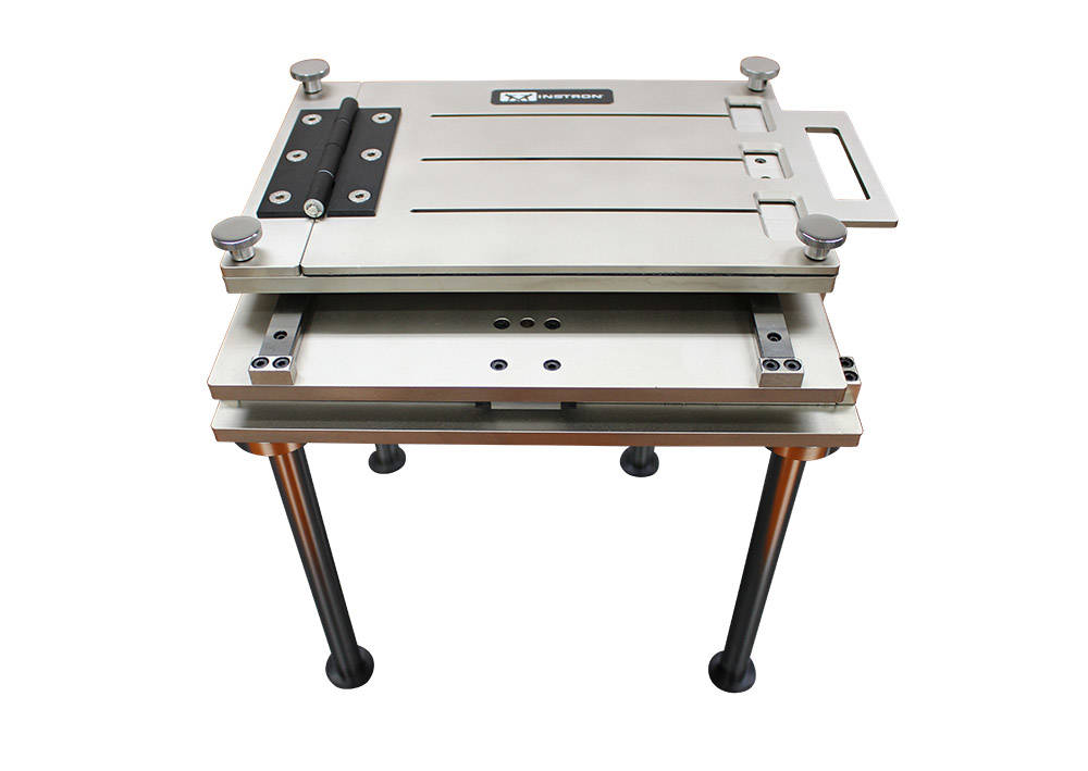
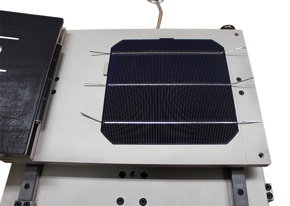
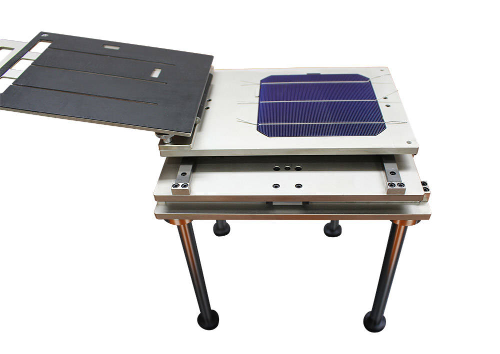
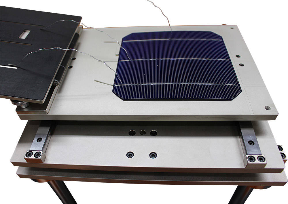
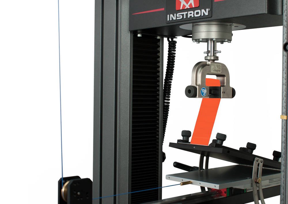
키패드 시험을 위한 기본 구성은 만능재료시험기(universal testing machine), 저하중 로드셀, 철재 압자를 잡기위한 chuck fixture로 되어있습니다. 여기에 핸드폰이나 키패드 모듈을 잡아주기 위한 판이나 티홈 테이블(t-slot table)이 사용됩니다. 시험 중에는 하중형태(load profile)와 때때로 버튼이 눌려질 때의 변위특성도 함께 측정됩니다.
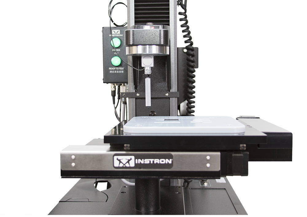
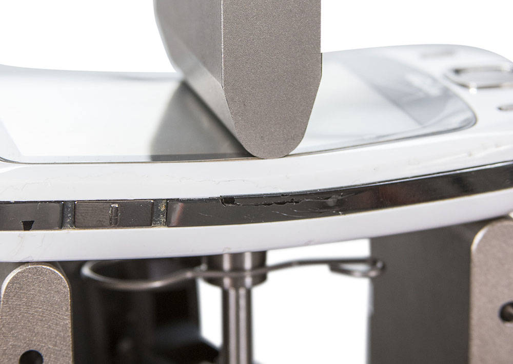
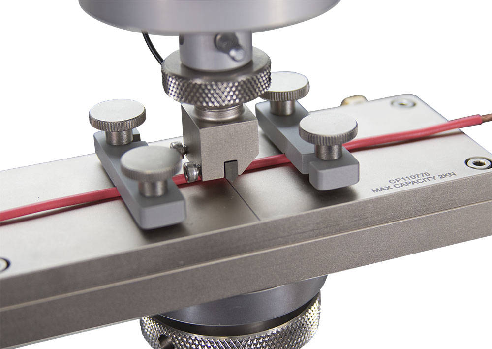
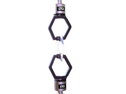
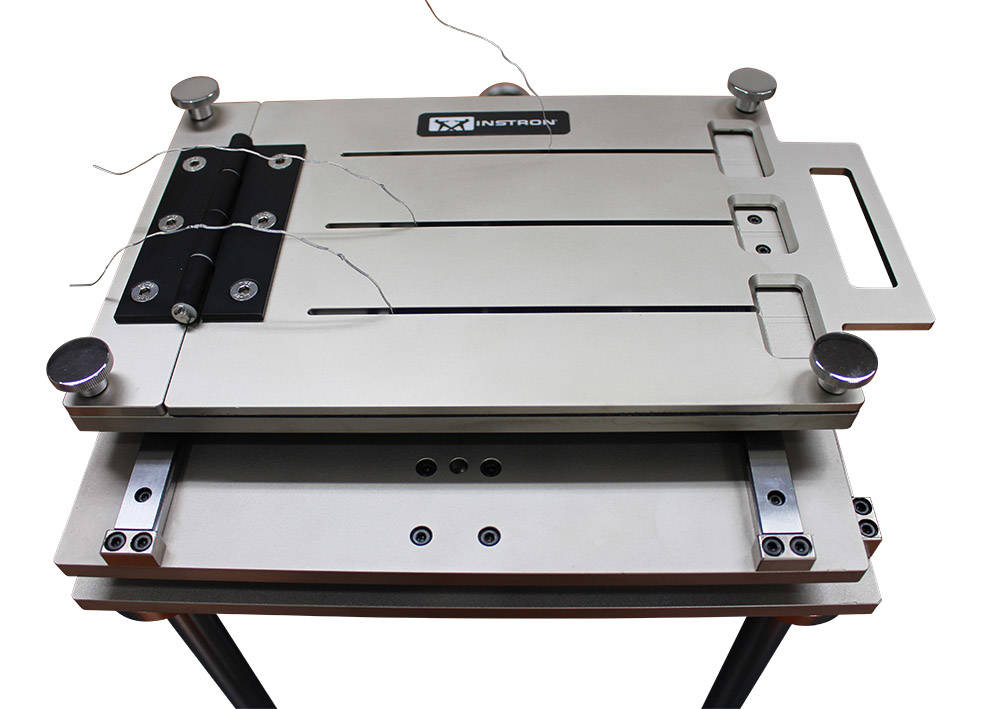
더욱 자세한 분석을 위해서는 전기접점을 장비에 연결하여 스위치의 작동 위치와 힘을 정밀하게 측정하기도 합니다. 정확한 데이터를 확보하기 위하여 고속 데이터 수집장치를 사용하여 스위치가 작동될 때 아주 미세한 위치변화에서 하중이 급히 변화되는 지점을 관찰할 수 있습니다. 사용되는 장비는 정밀한 부품에의 손상을 피하기 위하여 위치 정밀도가 높고 제어능력이 뛰어난 장비이어야 합니다.
Ultra High Precision Testing Systems. Mechanical Testing for Microelectronics R&D, production and other varieties of high accuracy, small scale testing.
Instron 6800 시리즈 만능 시험기는 최고의 정확도와 신뢰성을 제공합니다. 6800 시리즈는 완전히 새로운 Smart-Close Air Kit 및 Collision Mitigation 기능이 있는 특허 출원 중인 Operator Protect 시스템 아키텍처를 기반으로 하며, 그 어느 때보다 간편하고 스마트하며 안전한 소재 시험을 가능하게 합니다.
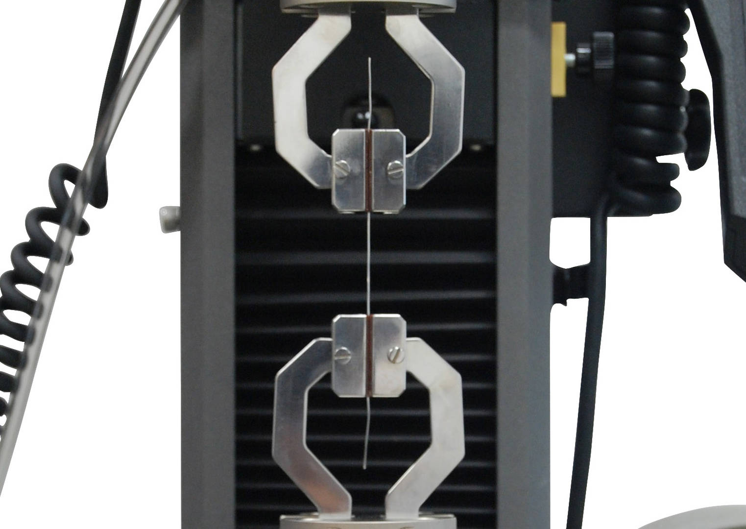
인장, 압축, 굽힘 및 기타 재료 특성 테스트를 위한 Instron 3400 시리즈 범용 테스트 시스템.
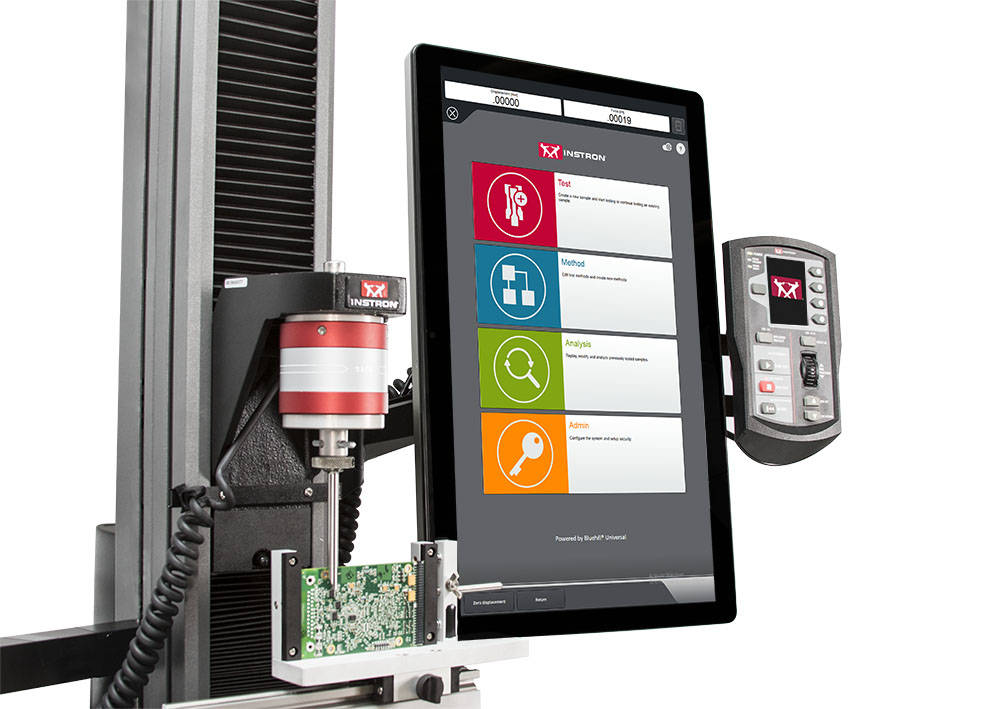
Bluehill Universal은 직관적인 터치 상호 작용과 간소화된 워크플로우를 위해 설계된 Instron의 고급 재료 시험 소프트웨어입니다. 이 소프트웨어는 사전 로드된 시험 방법, 빠른 설정을 위한 QuickTest, 향상된 데이터 내보내기, 그리고 직접적인 서비스 통신을 위한 Instron Connect를 제공합니다. Bluehill 2 및 Bluehill 3 사용자들은 향상된 성능과 사용 편의성을 위해 최신 버전으로 쉽게 업그레이드할 수 있습니다.
Instron 6800 시리즈 만능 시험기는 최고의 정확도와 신뢰성을 제공합니다. 6800 시리즈는 완전히 새로운 Smart-Close Air Kit 및 Collision Mitigation 기능이 있는 특허 출원 중인 Operator Protect 시스템 아키텍처를 기반으로 하며, 그 어느 때보다 간편하고 스마트하며 안전한 소재 시험을 가능하게 합니다.
Bluehill Universal은 직관적인 터치 상호 작용과 간소화된 워크플로우를 위해 설계된 Instron의 고급 재료 시험 소프트웨어입니다. 이 소프트웨어는 사전 로드된 시험 방법, 빠른 설정을 위한 QuickTest, 향상된 데이터 내보내기, 그리고 직접적인 서비스 통신을 위한 Instron Connect를 제공합니다. Bluehill 2 및 Bluehill 3 사용자들은 향상된 성능과 사용 편의성을 위해 최신 버전으로 쉽게 업그레이드할 수 있습니다.
Related


")