木材测试工装
木材材料的特性分析需要在不同载荷条件下进行一系列测试,例如拉伸、压缩、剪切和弯曲。Instron 提供一系列高性能木材测试工装,符合相应的 ASTM、ISO、EN、JIS 和其他测试标准的要求。
木材材料的特性分析需要在不同载荷条件下进行一系列测试,例如拉伸、压缩、剪切和弯曲。Instron 提供一系列高性能木材测试工装,符合相应的 ASTM、ISO、EN、JIS 和其他测试标准的要求。

请您填写下表,我们将尽快与您联系。我们的在线留言答复时间一般为 1-2 个工作日,如您需要尽快答复,请致电 400 820 2006,谢谢。


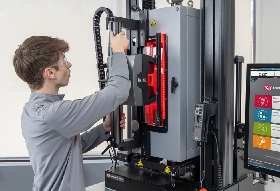
AVE3 可测量几乎所有应用场景下的弹性模量与断裂应变,包括平面及圆柱形试样的静态拉伸、弯曲和压缩试验。 在环境试验箱或流体浴槽中,可于常温或高低温条件下采集测量数据。无论您测试的是塑料、金属、复合材料、纺织品、薄膜、箔材、弹性体、纸张、零部件还是生物材料,AVE3 均能以卓越的灵活性满足不断变化的测试需求,并符合以下标准:
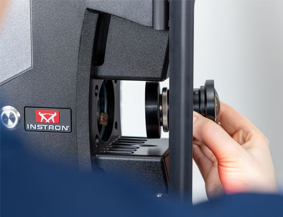
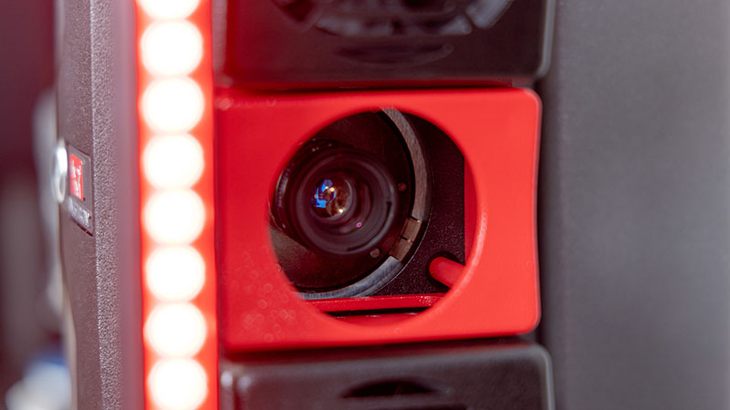
镜头根据您独特的测试设置进行配置,并在出厂时完成标定。光圈和焦距均被锁定,以消除操作人员的可能造成的任何影响。每个镜头均内置唯一识别编号,使试验系统能够通过磁吸安装自动识别设备编号。这种新的连接方法确保了镜头每次安装位置的可重复性。此外,AVE3 还采用简化标定板,在保持加载链完好无损的情况下直接夹在试样上,便于定期标定检查,确保您的设备始终处于最佳测试状态。
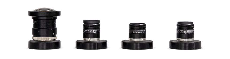
注:选择镜头时,请确保您了解最小和最大标距要求,以及您计划测试的试样范围的总延伸量。
借助全新 AVE3,您现在能够执行需要应变控制的测试,包括 ASTM E8 和 ISO 6892。AVE3 在精度和 500 Hz 数据采集率方面的进步,使您的试验系统能够对应变率的变化做出实时响应,从而帮助您快速、深入了解情况,确保测试结果具有可重复性和可比性,并严格符合国际测试标准的要求。
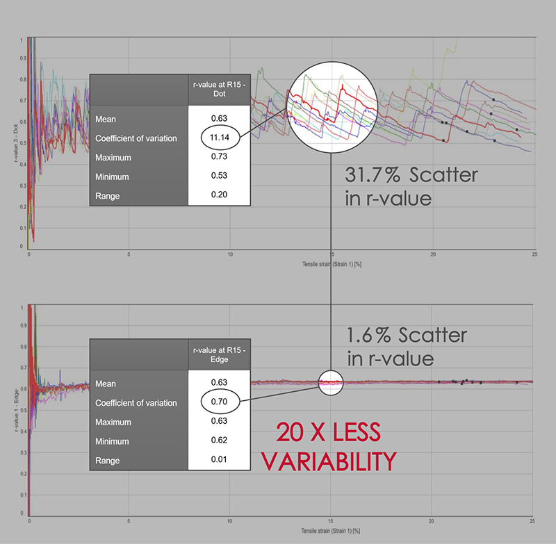
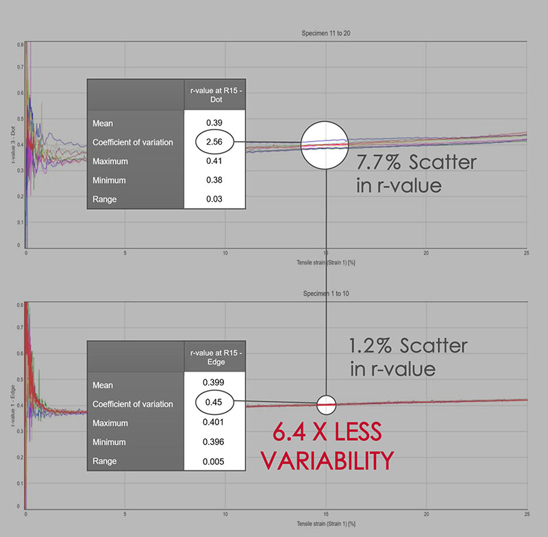
AverEdge32 是 AVE3 的一项可选高级功能,它利用边缘检测技术同时 测量试样标距长度上 32 个位置的横向应变。然后实时对这些数值进行平均, 得出平滑且可重复的横向应变值,这对于计算金属板材的 r 值至关重要。
数字图像相关(DIC)是一种光学技术,通过比较被测试样表面的图像来生成全场应变和位移图。生成的图像可用于直观显示被测试样整个二维表面的应变和位移。
英斯特朗的液压夹具泵专为大载荷试验提供精确可靠的夹持力而设计,载荷范围最高可达 600 kN。
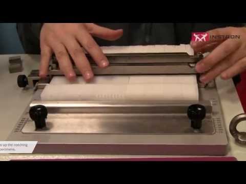
These machines are developed to obtain specimens by punching, using hollow dies of different sizes and contours. Several hundreds of dies can be created by interchangeable socket punches with different profiles and size according to the standards and to the customer needs. Dies are made of steel with hand finished cutting edges and can be provided with ejector for easy removal of the specimen after punching.
Compact design of instrument for an easy and fast preparation
Manual and automatic models obtain specimens of different size and geometries for a wide range of plastics testing applications
High level of results repeatability and time saving test procedures
For Universal Testing Systems
Our standard furnaces, mounts, grips, and load string assemblies for universal testing systems allow for testing up to 1200°C in air. Our engineered solutions group is also able to develop solutions to meet higher temperature requirements and additional furnace dimensions.
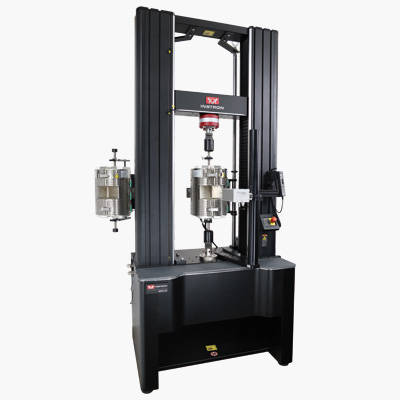
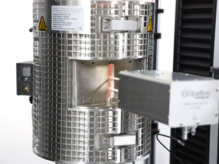
1200°C Three-Zone Split Tube Furnace
This three-zone split tube furnace features a side entry extensometer port and is manufactured with a wire-wound element for maximum operation up to 1200°C (2200°F). The elements are uniquely formed to provide optimum temperature uniformity, ensuring conformance with testing standards such as ASTM E21, ISO 6892-2, EN10002-5,and EN2002-2. The top and bottom furnace endplates are durable, provide excellent insulation, and include a 20 mm (0.787 in) diameter hole for use with pull rods.
| Specifications | |||
| Specimen Temperature Range | 200 - 1050°C (392 - 1922°F) | ||
| Overall Heated Length | 300 mm (11.81 in) | ||
| Interior Diameter | 75 mm (2.95 in) | ||
Mounting brackets are used to securely attach the furnace to the test system.
| Specifications | |||
| Description | Catalog No. | ||
| Floor Model Standard Furnace Mounting A standard 3-knuckle design furnace mounting that allows for manual adjustments. | CP119938 | ||
| Floor Model Advanced Furnace Mounting The advanced mounting allows for quick and easy fine adjustments of the vertical position of the furnace as well as parallelism to the load string. | CP107737 | ||


Three-Zone Temperature Control Systems
Temperature control systems are designed for controlling the heat output of furnaces. The control systems can be configured to operate nearly any furnace with any one of several different thermocouples types. Three zone control systems are designed for heat-only furnaces with three separate zones of heating elements, and typically three different thermocouples to control those zones.
| Specifications | |||
| Description | Catalog No. | ||
| Type K Control System | 3119-960 | ||
| Type R/S Control System | 3119-962 | ||
| Stepdown Transformer The wall mount 3KVA stepdown transformer assembly provides the ability to operate the 120V, single phase Model TCS3203 3-zone furnace control system from 190/200/208/220V, 50/60Hz power sources. | W-C015-TRAN | ||

Quick-change adapters are typically used in hot tensile applications to provide simplified load train installation. They consist of a button-head washer that is threaded onto the room temperature end of a pull rod. The washer and pull rod are then inserted through a slot in the adapter body.
| Specifications | |||
| Force Capacity | Effective Length | Catalog No. | |
| 90 kN | 6.43 in | W-7556M4 | |
| 10 kN | 5.58 in | W-7556M2 | |
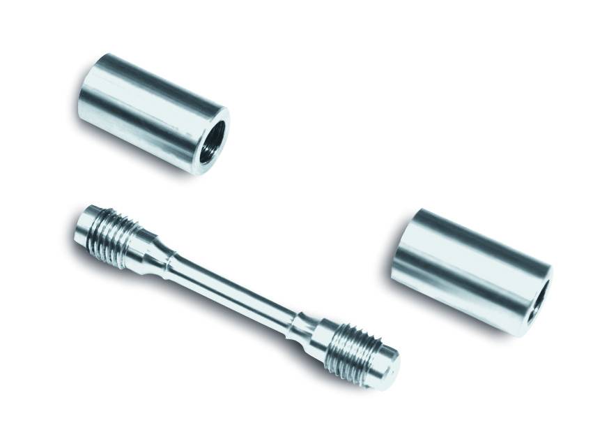
Threaded End Specimen Holders
Catalog No. W-7551-C
Threaded-end specimen holders made of Inconel 713-C rated for a maximum temperature of 1100 Deg. C (2000 Deg. F).
| Specifications | ||
| Specimen Thread Size | Catalog No. | |
| Metric M6 x 1.0 | W-7551-CM1 | |
| Metric M8 x 1.0 | W-7551-CM2 | |
| Metric M8 x 1.25 | W-7551-CM3 | |
| Metric M10 x 1.5 | W-7551-CM4 | |
| Metric M12 x 1.5 | W-7551-CM5 | |
| Metric M12 x 1.75 | W-7551-CM6 | |
| Metric M14 x 2.0 | W-7551-CM7 | |
| Metric M16 x 1.5 | W-7551-CM8 | |
| Metric M16 x 2.0 | W-7551-CM9 | |
| Metric M18 x 2.5 | W-7551-CM10 | |
| Metric M19 x 1.5 | W-7551-CM11 | |
| US Customary 10-24 | W-7551-CU1 | |
| US Customary 10-32 | W-7551-CU2 | |
| US Customary 1/4-20 | W-7551-CU3 | |
| US Customary 1/4-28 | W-7551-CU4 | |
| US Customary 5/16-24 | W-7551-CU5 | |
| US Customary 5/16-18 | W-7551-CU6 | |
| US Customary 3/8-16 | W-7551-CU7 | |
| US Customary 3/8-24 | W-7551-CU8 | |
| US Customary 7/16-14 | W-7551-CU9 | |
| US Customary 1/2-13 | W-7551-CU10 | |
| US Customary 5/8-11 | W-7551-CU11 | |
| US Customary 3/4-10 (Type R3f) | W-7551-CU12 | |
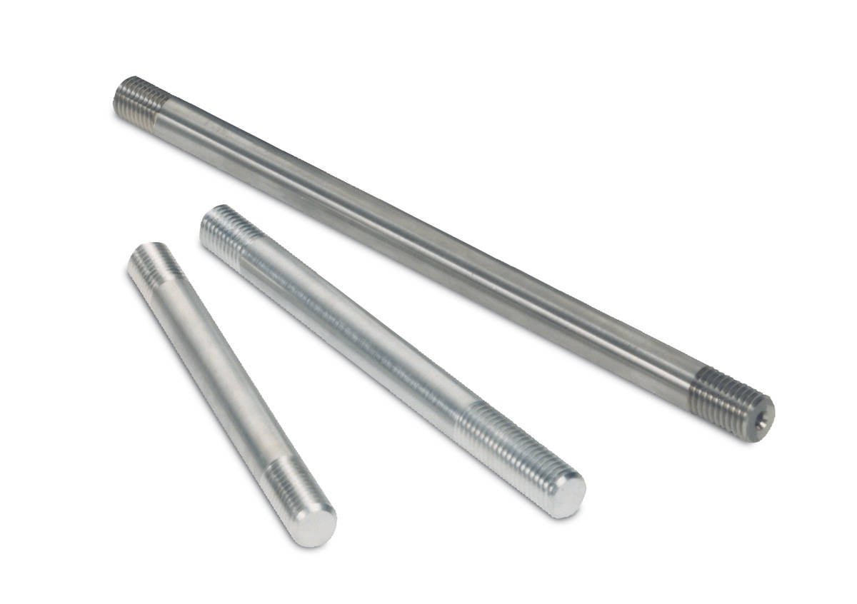
Pull Rods
High temperature pull rods made of made of Inconel 713-C for strength and resistance to corrosion and oxidation. Both ends are threaded 0.75-10m-RH and are compatible with a range of grips, adapters, and specimen holders.
Rated for 9070 kgs (20,000 lbs) load up to 760°C (1400°F) and 1360 kgs (3000 lbs) load at a maximum temperature of 1100°C (2000°F).
| Specifications | |||
| Pull Rod Length | Force Capacity | Catalog No. | |
| 273 mm (10.75 in) | 90 / 26.7 kN | W-7546-C | |
| 330 mm (13.00 in) | 90 / 26.7 kN | W-7547-C | |
High Temperature Tension Wedge Grips
Catalog No. W-7554
One set (2) wedge grip specimen holders made of Hastelloy X. Holders designed for tension-only loading and may be equipped to accept flat specimens from 1.13 mm to 3.18 mm thick (0.005 in to 0.125 in) by 12.7 mm to 22.225 mm wide (0.5 in to 0.875 in). Design of holders requires drilling of holes in specimen end tabs for initial loading and jaw alignment. Centering pin diameter 4.1148 mm (0.162 in). Holders are 70mm (2.75 in) long by 38mm (1.375 in) diameter contain 0.75-10f-RH thread for attachment to pull rods. Jaw inserts ordered separately, selected based on thicknesses of specimens to be tested. See W-7554-A1, -A3, and -A4 below for available inserts and corresponding thickness ranges.
| Specifications | |||
| Specimen Diameter | Pin 4.1148 mm (Pin 0.162 in) | ||
| Specimen Thickness | 1.13 - 3.18 mm (0.005 - 0.125 in) | ||
| Specimen Width | 12.700 - 22.225 mm (0.500 - 0.875 in) | ||
| Temperature Rating | 926°C (1700°F) | ||
High Temperature Wedge Jaw Inserts
One set (two pairs) of high temperature wedge jaw inserts for use with the W-7554 high temperature tension wedge grips.
| Specifications | |||
| Type | Specimen Thickness | Temperature Rating | Catalog No. |
| Smooth-Faced | 0.13 to 1.0 mm (0.005 to 0.040 in) | 926°C (1700°F) | W-7554-A1 |
| Serrated-Faced | 1.0 to 2.0 mm (0.040 to 0.078 in) | 926°C (1700°F) | W-7554-A3 |
| Serrated-Faced | 2.0 to 3.18 mm (0.078 to 0.125 in) | W-7554-A4 | |

Pin and Clevis Holders
Pin and clevis specimen holders are designed for flat specimens that have a hole in each end. The specimen fits into the slot of the holder and is secured by the pin.
Note: Using a specimen that is smaller (thinner) than the slot width specified for a given set of holders can result in misalignment of the specimen.
| Specifications | |||
| Material | Iconel 713-C | ||
| Temperature Rating | 1100°C (2000°F) | ||
| Upper and Lower Fittings | US Customary 3/4 in-10 (Type R3f) | ||
| Coupling Length | 69.9 mm (2.75 in) | ||
| Coupling Diameter | 28.6 mm (1.125 in) | ||
| Available Sizes | |
| Size | Catalog No. |
| 1 mm slot, 3 mm pin | CP112249 |
| 2 mm slot, 3 mm pin | CP112250 |
| 3 mm slot, 4 mm pin | CP112251 |
| 4 mm slot, 4 mm pin | CP112252 |
| 6 mm slot, 6 mm pin | CP112253 |
| 10 mm slot, 10 mm pin | CP112255 |
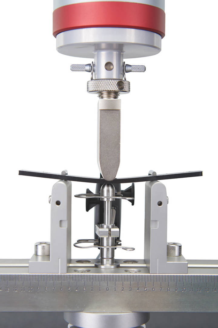
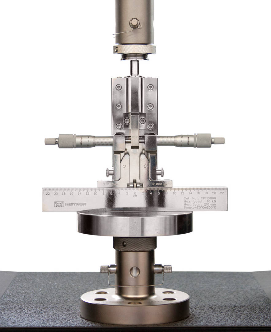
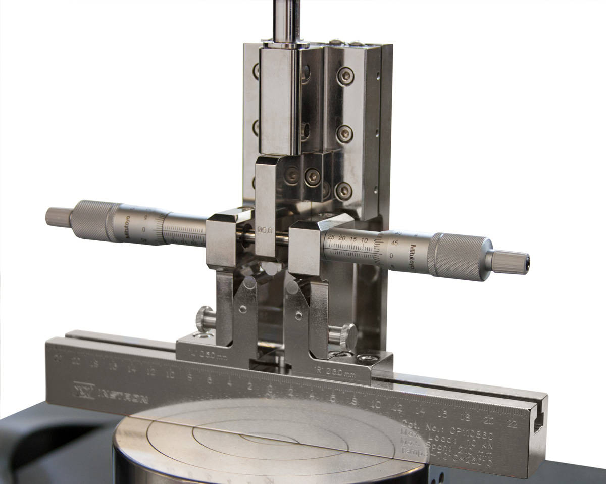
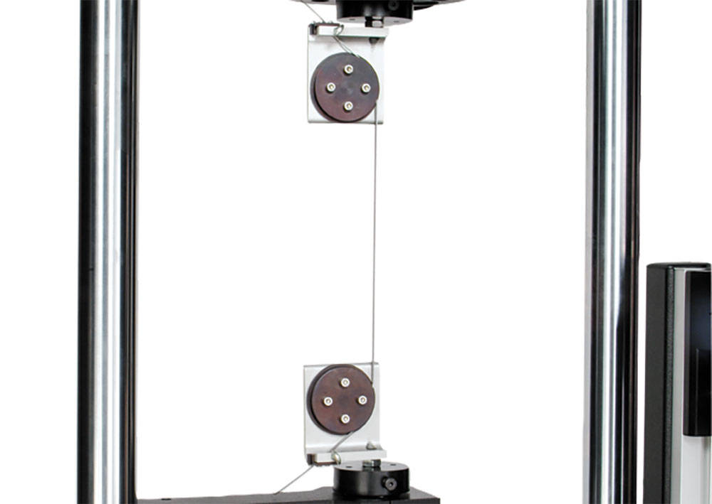
用于弯曲、挠曲和断裂韧性粘合测试

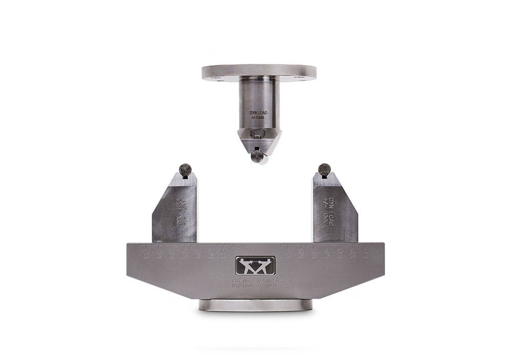
弯曲工装可用于进行多种弯曲试验和断裂韧性粘合试验,包括测定弯曲模量、弯曲强度和弯曲屈服强度。 易于安装的三点夹具可以通过可选的转换套件进行修改,以提供四点弯曲转换。下砧可调,以适应不同跨度的样品。样品的挠度可以通过横梁位移来测量,或者为了更精确的测量,您可以使用带有夹式引伸计的中跨直接测量柱塞。

工作原理
试样由两个具有确定半径的精密加工砧支撑。力施加在中心(3 点)或中心任一侧的确定距离处(4 点)。支撑梁以公制单位纵向分级,用于准确定位砧,等间距到中心线。
特点
应用范围
加载类型:静态弯曲、循环弯曲试验
试样材料:塑料、金属、合金、复合材料、陶瓷和其他材料
试样形状:条、棒、组件
常用标准: ASTM D790、ISO 178
| 规格 | |
|---|---|
| 目录号 | 2810-400 |
| 最大容量 | 5 kN (1125 lbf, 500 kgf) |
| 温度范围 | -100 °C 至 350 °C (-148 °F 至 660 °F) |
| 可调跨距距离 | 10 - 200 mm (0.39 - 7.87 in) |
| 查看完整规格 | 下载宣传册 |
Today's testing laboratories and manufacturers have a wide variety of material and component testing needs. To meet these varying requirements, Instron has several accessories designed to help interface with external equipment and measuring devices.
2810-500/505


操作原理适合静态和动态弯曲试验,该弯曲工装可配置为三点或四点(需加装2810-505)装置。试样放置在两个下支撑滚轴上,通过单个加载滚轴或是四点弯曲配置时的两个上加载滚轴,对试样中心施加载荷。
该工装具有18–148 mm(0.7–5.82 in)的可变跨距,适用于各种试样长度。下部和上部均装有一个法兰附件,可与所有新型ElectroPuls®试验机(除了E1000)直接兼容。
试样放置于两个下支撑上,上支撑滚轴用于在试样上施加反向的力。这允许进行高周弯曲疲劳试验。
应用范围
如需了解更多信息,请下载资料
访问ElectroPuls网页
Revolutionary Strain Control


Revolutionary Strain Control


If you want to protect your strain measurement device from damaging shock loads then contact us to discuss your non-contacting strain application today.
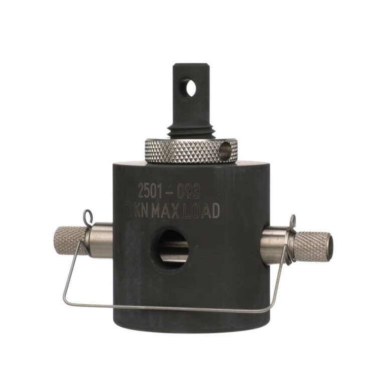
销连接转销连接转接头用于连接接口比载荷传感器或机架底座更大或更小的夹具和工装。
| 适用型号 | |||
| 接口 1 | 接口 2 | 连接方式 | 目录编号 |
| 公头 - OO 型 (6 mm 外径接头,带有 2.5 mm 直径销子) |
母头 - O 型 (12 mm 内径接头,带有 6 mm 直径销子) |
刚性 | 2501-350 |
| 公头 - OO 型 (6 mm 外径接头,带有 2.5 mm 直径销子) |
母头 - C 型 (5/8 in内径接头,带有 1/4 in 直径销子) |
刚性 | S1-13807 |
| 公头 - O 型 (12 mm 外径接头,带有 6 mm 直径销子) |
母头 - B 型 (1/2 in 内径接头,带有 3/16 in 直径销子) |
刚性 | 2501-134 |
| 公头 - O 型 (12 mm 外径接头,带有 6 mm 直径销子) |
母头 - C 型 (5/8 in 内径接头,带有 1/4 in 直径销子) |
刚性 | 2501-133 |
| 公头 - O 型 (12 mm 外径接头,带有 6 mm 直径销子) |
母头 - D 型 (1.25 in 内径接头,带有 1/2 in 直径销子) |
刚性 | 2501-093 |
| 公头 - D 型 (1.25 in 外径接头,带有 1/2 in 直径销子) |
母头 - O 型 (12 mm 内径接头,带有 6 mm 直径销子) |
刚性 | 2501-346 |
| 公头 - D 型 (1.25 in 外径接头,带有 1/2 in 直径销子) |
母头 - B 型 (1/2 in 内径接头,带有 3/16 in 直径销子) |
刚性 | 2501-119 |
| 公头 - D 型 (1.25 in 外径接头,带有 1/2 in 直径销子) |
母头 - C 型 (5/8 in 内径接头,带有 1/4 in 直径销子) |
刚性 | 2501-120 |
| 公头 - D 型 (1.25 in 外径接头,带有 1/2 in 直径销子) |
母头 - 1 型 (34 mm 内径接头,带有 16 mm 直径销子) |
刚性 | 2501-338 |
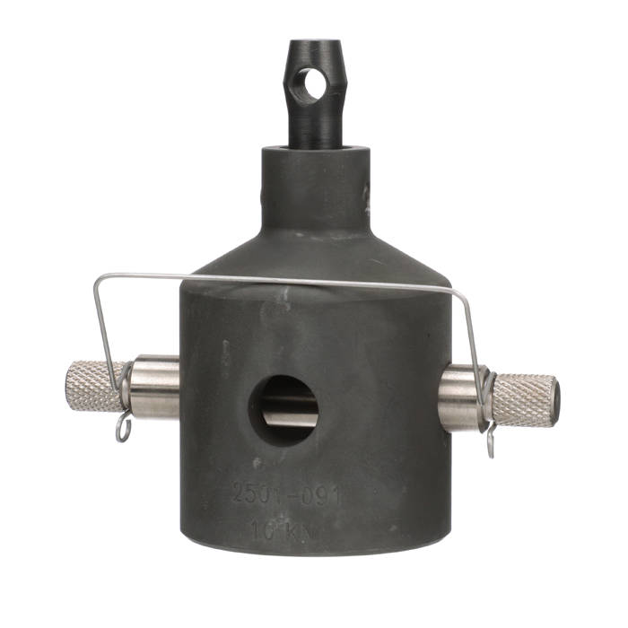
销连接转销连接转接头用于连接比载荷传感器或机架底座具有更大或更小接头的夹具和工装。柔性转接头用于某些测试应用的试样对中。
| 适用型号 | |||
| 接口 1 | 接口 2 | 连接方式 | 目录编号 |
| 公头 - OO 型 (6 mm 外径接头,带有 2.5 mm 直径销子) |
母头 - B 型 (1/2 in 内径接头,带有 3/16 in 直径销子) |
柔性 | 2501-115 |
| 公头 - OO 型 (6 mm 外径接头,带有 2.5 mm 直径销子) |
母头 - C 型 (5/8 in 内径接头,带有 1/4 in 直径销子) |
柔性 | 2501-157 |
| 公头 - O 型 (12 mm 外径接头,带有 6 mm 直径销子) |
阴头 - O 型 (12 mm 内径接头,带有 6 mm 直径销子) |
柔性 | 2501-348 |
| 公头 - O 型 (12 mm 外径接头,带有 6 mm 直径销子) |
母头 - B 型 (1/2 in 内径接头,带有 3/16 in 直径销子) |
柔性 | 2501-109 |
| 公头 - O 型 (12 mm 外径接头,带有 6 mm 直径销子) |
母头 - C 型 (5/8 in 内径接头,带有 1/4 in 直径销子) |
柔性 | 2501-094 |
| 公头 - O 型 (12 mm 外径接头,带有 6 mm 直径销子) |
母头 - D 型 (1.25 in 内径接头,带有 1/2 in 直径销子) |
柔性 | 2501-091 |
| 公头 - D 型 (1.25 in 外径接头,带有 1/2 in 直径销子) |
母头 - D 型 (1.25 in 内径接头,带有 1/2 in 直径销子) |
柔性 | 2501-356 |
| 公头 - 1 型 (34 mm 外径接头,带有 16 mm 直径销子) |
母头 - C 型 (5/8 in 内径接头,带有 1/4 in 直径销子) |
柔性 | 2501-170 |
| 公头 - 1 型 (34 mm 外径接头,带有 16 mm 直径销子) |
母头 - D 型 (1.25 in 内径接头,带有 1/2 in 直径销子) |
柔性 | 2501-090 |
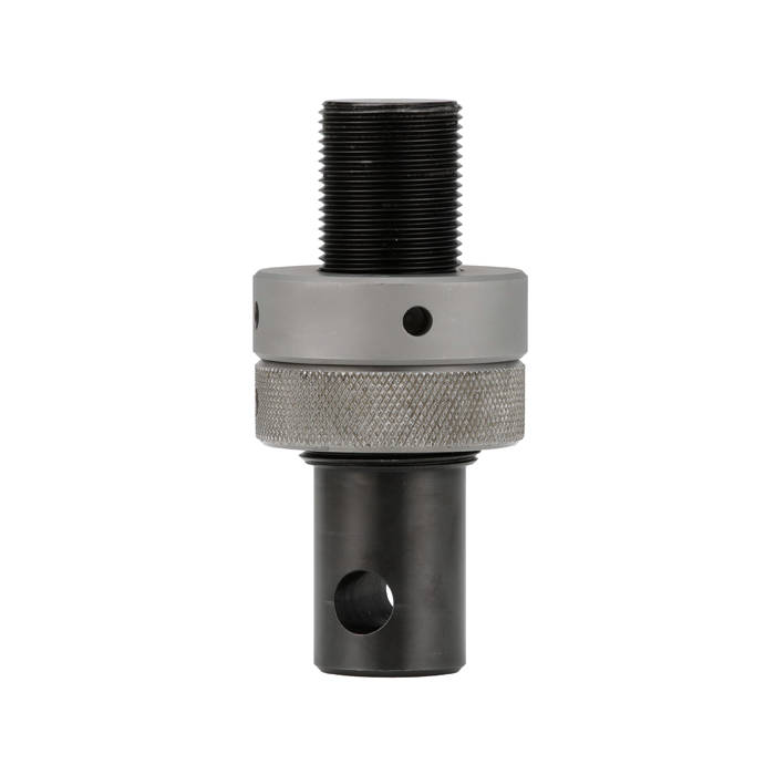
在落地式系统上,当力传感器或机架是螺纹接口时,销连接转螺纹转接头可用于连接相关的夹具和工装。
| 适用型号 | |||
| 接口 1 | 接口 2 | 连接方式 | 目录编号 |
| 公头 - D 型 (1.25 in 外径接头,带有 1/2 in 直径销子) |
公头 - I 型 (M30x2 右旋螺纹) |
刚性 | 2501-173 |
| 公头 - D 型 (1.25 in 外径接头,带有 1/2 in 直径销子) |
公头 - II 型 (M48x2 右旋螺纹) |
刚性 | 2501-172 |
| 公头 - 1 型 (34 mm 外径接头,带有 16 mm 直径销子) |
母头 - O 型 (12 mm 内径接头,带有 6 mm 直径销子) |
刚性 | 2501-159 |
| 公头 - 1 型 (34 mm 外径接头,带有 16 mm 直径销子) |
母头 - D 型 (1.25 in 内径接头,带有 1/2 in 直径销子) |
刚性 | 2501-092 |
| 公头 - 1 型 (34 mm 外径接头,带有 16 mm 直径销子) |
公头 - I 型 (M30x2 右旋螺纹) |
刚性 | 2501-073 |
| 公头 - 1 型 (34 mm 外径接头,带有 16 mm 直径销子) |
公头 - II 型 (M48x2 右旋螺纹) |
刚性 | 2501-171 |
| 公头 - I 型 (M30x2 左旋螺纹) |
母头 - D 型 (1.25 in 内径接头,带有 1/2 in 直径销子) |
刚性 | 8005-061 |
| 公头 - II 型 (M48x2 左旋螺纹) |
母头 - D 型 (1.25 in 内径接头,带有 1/2 in 直径销子) |
刚性 | 8005-062 |
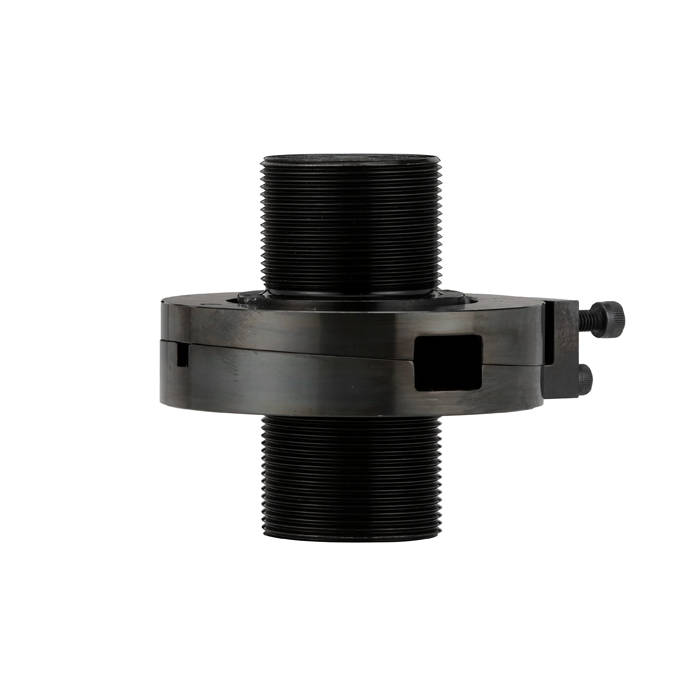
螺纹转接头通常用于夹具和工装以实现高载荷测试。大多数液压载荷链、超过 100 kN 的载荷链,以及带有螺纹底座和载荷传感器连接的系统,都需要螺纹转接头。
| 适用型号 | |||
| 接口 1 | 接口 2 | 连接方式 | 目录编号 |
| 公头 - II 型 (M48x2 左旋螺纹) |
母头 - 1.5 in -12 右旋螺纹 | 刚性 | 2501-206 |
| 公头 - II 型 (M48x2 左旋螺纹) |
母头 - I 型 (M30x2 左旋螺纹) |
刚性 | 2501-205 |
| 公头 - II 型 (M48x2 左旋螺纹) |
母头 - 2 in -12 右旋螺纹 | 刚性 | 8005-022 |
| 公头 - I 型 (M30x2 左旋螺纹) |
公头 - I 型 (M30x2 右旋螺纹) |
刚性 | 8005-041 |
| 公头 - I 型 (M30x2 左旋螺纹) |
公头 - II 型 (M48x2 右旋螺纹) |
刚性 | 8005-045 |
| 公头 - II 型 (M48x2 左旋螺纹) |
公头 - I 型 (M30x2 右旋螺纹) |
刚性 | 8005-046 |
| 公头 - II 型 (M48x2 左旋螺纹) |
公头 - II 型 (M48x2 右旋螺纹) |
刚性 | 8005-042 |
| 公头 - IIA 型 (M72x3 左旋螺纹) |
公头 - IIA 型 (M72x3 右旋螺纹) |
刚性 | 8005-043 |
设备底座转接头通常用于将夹具或工装连接到设备上。在载荷范围为 10 kN 及以下的设备上,使用带螺丝通孔的销连接接头。在载荷范围为 30 kN、50 kN 和 100 kN 的设备上,使用带销连接的法兰适配器。对于载荷容量超过 100 kN 的设备,请参阅“螺纹转接头”部分。
| 适用型号 | |||
| 接口 1 | 接口 2 | 连接方式 | 目录编号 |
| 6 x M10 螺栓分布圆 | 母头 - D 型 (1.25 in 内径接头,带有 1/2 in 直径销子) |
刚性 | 2501-113 |
| 6 x M10 螺栓分布圆 | 母头 - II 型 (M48x2 左旋螺纹) |
刚性 | 2501-148 |

力传感器快接头使高达50kN的载荷传感器更易安装在横梁上。接头的一部分安装在横梁上,另一部分安装在载荷传感器上,使载荷传感器能够独立牢固地悬挂在横梁下,轻松拧紧螺栓完成安装。另配有载荷传感器转接头,可搭配多种载荷传感器使用。
| 适用型号 | |
| 描述 | 目录编号 |
| 用于 5900 或 6800 台式机到 2580、2530 和 2525 系列载荷传感器的全套套件 (包含横梁接头和一个载荷传感器接头) |
2501-212 |
| 适用于 500 N - 5 kN 2580 载荷传感器的快接头 | 2501-213 |
| 适用于 10 kN - 50 kN 2580 载荷传感器的快接头 | 2501-214 |
| 适用于 5 N - 5 kN 2530 载荷传感器的接头 | 2501-215 |
搭接载荷传感器转接头使系统的主载荷传感器在不拆卸的情况下安装小力值传感器。
| 适用型号 | ||||
| 兼容的主载荷传感器连接方式 | 兼容的次级载荷传感器 | 目录编号 | ||
| D 型 | 500 N 到 5 kN 用于安装 2580 系列载荷传感器。 | 2501-208 | ||
| D 型 | 5 N 到 5 kN 用于安装 2530 系列载荷传感器。 | 2501-210 | ||
| D 型 | 10 kN 到 50 kN 用于安装 2580 系列载荷传感器。 | 2501-209 | ||
| II 型 (M48) | 500 N 到 50 kN 2580 系列,500 N 至 50 kN(M10 或 M16 安装螺栓) 2530 系列,500 N 至 50 kN(M10 或 M16 安装螺栓) 2525 系列,50 kN 或以下 2519 系列,10 N 至 5 kN(M6 或 M10 安装螺栓) 2518 系列,50 kN 或以下 |
2501-227 | ||
| IIA 型(M72) | 500 N 至 50 kN 2580 系列,500 N 至 50 kN(M10 或 M16 安装螺栓) 2530 系列,500 N 至 50 kN(M10 或 M16 安装螺栓) 2525 系列 – 500 N 至 50 kN 2519 系列,10 N 至 5 kN(M6 或 M10 安装螺栓) |
2501-228 | ||
搭接载荷链转接头使不拆卸大载荷夹具的情况下,同时安装其他工装。
| 适用型号 | ||||
| 主夹具 | 提供的连接方式 | 目录编号 | ||
| 100 kN 液压楔形夹具(目录编号 2743-401) | Df 型(紧凑型) | 2501-258 | ||
| 100 kN 液压楔形夹具(目录编号 2743-401) | Df 型 | 2501-260 | ||
| 300 kN 液压楔形夹具(目录编号 2742-501) | II 型(M48) | 2501-255 | ||
| 300 kN 液压楔形夹具(目录编号 2742-501) | Df 型 | 2501-256 | ||
| 600 kN 液压楔形夹具(目录编号 2743-601) | IIA 型(M72) | 2501-259 此转接头只能用于压缩测试。 | ||
| 100 kN 精密手动楔形夹具(目录编号 2716-028) 250 kN 精密手动楔形夹具(目录编号 2716-030) |
Df 型 | 2501-700 | ||
| 100 kN 精密手动楔形夹具(目录编号 2716-028) 250 kN 精密手动楔形夹具(目录编号 2716-030) |
II 型(M48) | 2501-702 | ||

贯通式传感器快接头可将 2580 系列传感器安装到传统 Instron 万能试验系统,以及升级改造至 6800 试验系统的设备上。这些转接头可直接穿过横梁安装,适用于最大载荷范围为 100 kN 的台式和落地式试验系统。
| 适用型号 | ||||
| 机架兼容性 | 传感器兼容性 | 最大间距 | 目录编号 | |
| 4464、4465、4466、5564、5565、5566 | 2580 系列 (500 N - 10 kN) |
153 mm | 2501-290 | |
| 4467、4469、5567、5569 | 2580 系列 (500 N - 10 kN) |
165 mm | 2501-291 | |
| 4481、5581 | 2580-50kN (50 kN) |
133 mm | 2501-291 | |
| 4482、5582 | 2580-100kN (100 kN) |
111 mm | 2501-292 | |
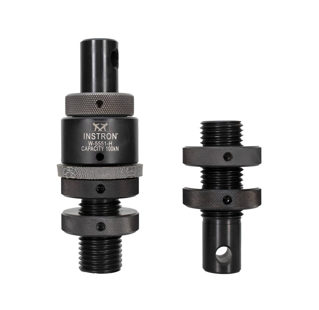
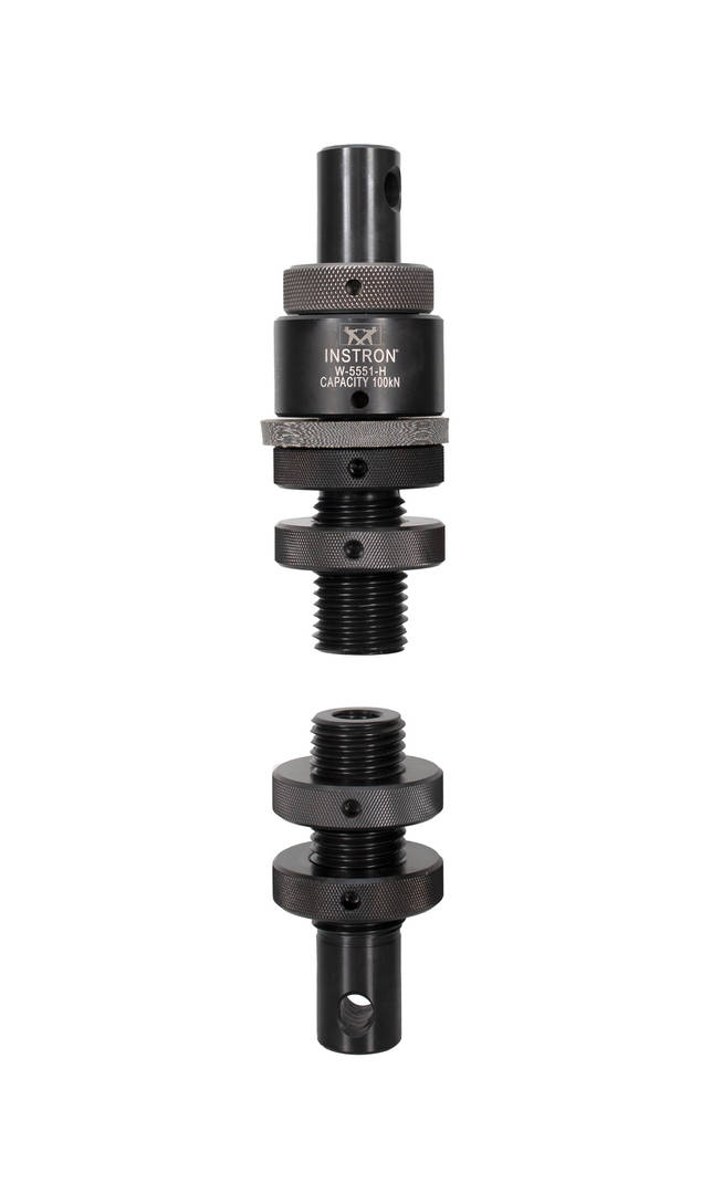
当同轴度对某一测试应用非常重要时,万向球面拉伸接头 (USTA) 套件可提供独特的球面移动,进行少量补偿。这些螺纹转接头用于将拉伸工装安装到载荷传感器或机架底座上,或用于次级载荷链连接。
| 适用型号 | ||||
| 载荷范围 | 端部 1 机器接口 | 端部 2 附件接口 | 连接方式 | 目录编号 |
| 300 kN | IIm 型 (M48x2m LH) |
300 kN 载荷:R4m 型(M36x4) 100 kN 载荷:R3f 型(0.75-10) |
一端球面 一端刚性 |
W-5551-A |
| 300 kN 缩短 |
IIm 型 (M48x2m LH) |
载荷范围:R4m 型(M36x4) 100 kN 载荷范围:R3f 型(0.75-10) |
一端球面 一端刚性 |
W-5551-G |
| 300 kN | IIm 型 (M48x2m LH) |
300 kN 载荷范围:R4m 型(M36x4) 100 kN 载荷范围:R3f 型(0.75-10) |
双球面 | W-5551-B |
| 100 kN | Dm 型 (1.25 in 接头) |
载荷范围:R4m 型(M36x4 RH) 100 kN 载荷范围:R3f 型(0.75 in -10 RH) |
一端球面 一端刚性 |
W-5551-H |
| 300 kN 螺纹转接头轴衬套件 | R4f 型(M36x4f) | 刚性 | W-5551-D | |
| 600 kN | IIAm 型 (M72x3m LH) |
600 kN 载荷范围:IIm 型(M48x2m) 100 kN 载荷范围:R3f 型(0.75-10)螺纹 |
一端球面 一端刚性 |
W-5552-A |
| 600 kN | IIAm 型 (M72x3m LH) |
600 kN 载荷范围:IIm 型(M48x2m) 100 kN 载荷范围:R3f 型(0.75-10)螺纹 |
双球面 | W-5552-B |
| 400 kN | IIm 型 (M48x2m LH) |
400 kN 载荷范围:IIm 型(M48x2m) 100 kN 载荷范围:R3f 型(0.75-10)螺纹 |
一端球面 一端刚性 |
W-5552-E |
| 400 kN | IIm 型 (M48x2m LH) |
400 kN 载荷范围:IIm 型(M48x2m) 100 kN 载荷范围:R3f 型(0.75-10)螺纹 |
双球面 | W-5552-F |
| 600 kN 螺纹转接头轴衬套件 | IIf 型(M48x2f) | 刚性 | W-5552-G | |
适用于多种材料和试样类型的多功能夹持解决方案
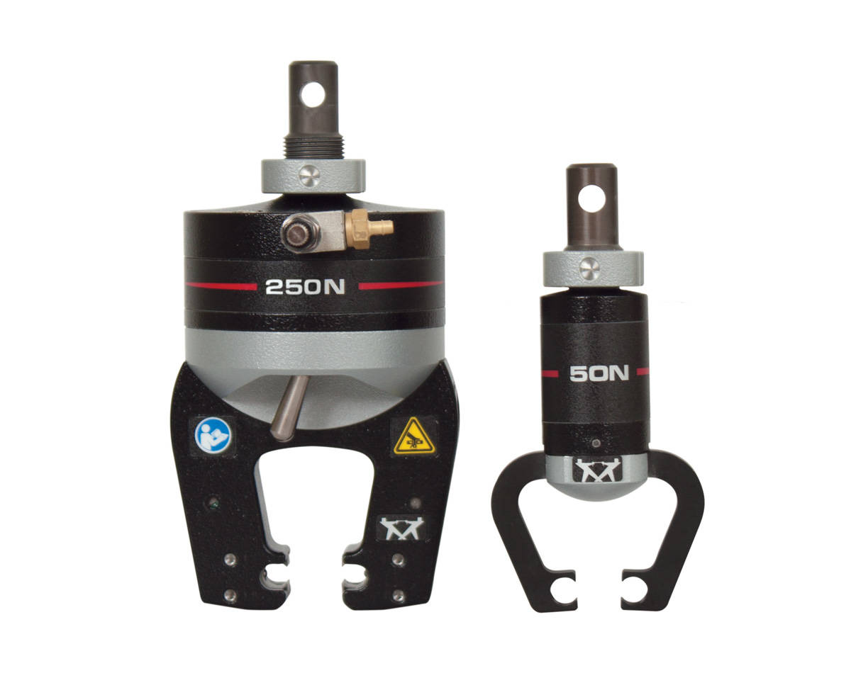
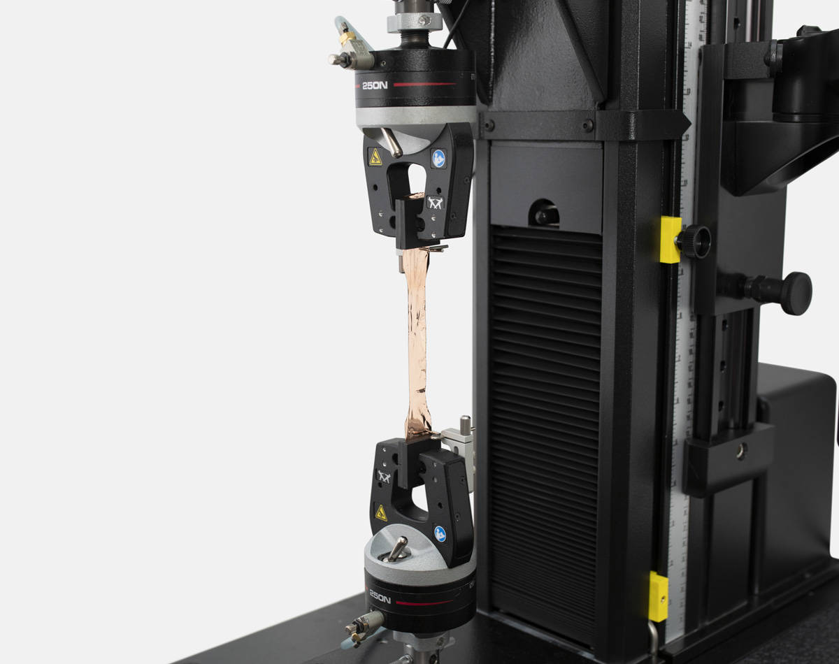
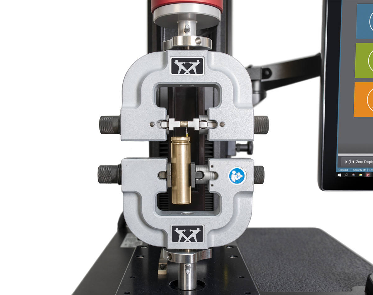
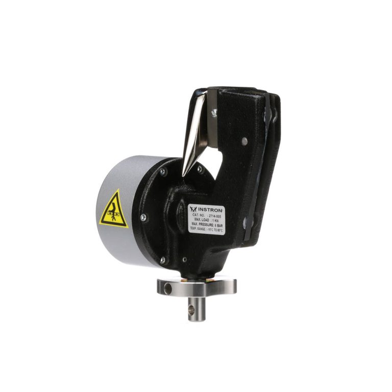
气动平推夹具是夹取各种材料和试样的有效解决方案,包括纤维、导线、薄片、箔材、薄膜、纺织品、塑料、弹性体和组件。可重复的夹持力和操作速度使气动夹具成为各种测试应用的理想选择。此外,2712-04x 和 2712-05x 夹具还有许多增强功能,包括夹面防护罩、超快夹面更换和可选配的试样对中装置,进一步提高了易用性、可重复性和操作安全性。
50 N - 10 kN 受力能力
针对高温和低温测试要求,温度额定气动夹具为在温控环境中夹持各种材料提供便利。

气动夹具通过双杠杆臂夹持试样,由内置在夹具主体中的气缸驱动。夹持力可通过调节输入气压进行控制,即便试样在夹持区域发生收缩,夹持力仍能保持恒定,试样在试验过程中不会打滑。气动夹具可通过脚踏开关或安装在夹具上的气阀(大多数型号)进行操作,相较于手动平推夹具,操作更为快捷简便。
| 载荷范围 | 目录编号 |
|---|---|
| 50 N | 2712-051 |
| 250 N | 2712-052 |
| 1 kN | 2712-041 |
| 2 kN | 2712-042 |
| 5 kN | 2712-045 |
| 10 kN | 2712-046 |
轻扫旋转


保护操作人员免受夹伤风险
夹面防护罩
保护手指免受夹面之间的夹伤危险(专利申请中)。
可调式气流控制阀
可调式气流控制阀可用于减慢夹面闭合速度,以防止事故发生。
可调节开口
1、2、5 和 10 kN 型号的夹口面开口可调,可根据试样厚度进行设置。
无需任何工具即可轻松更换夹具和夹面

![]()
独特的锁紧螺母设计
专为轻松舒适的手动拧紧设计,以消除反向间隙。螺纹间距较小,也更容易施加所需的预紧力。

速释空气软管
可旋转连接设计可实现整洁的软管布置。快速连接功能使空气供应的断开操作快速简便。
旨在提高测试量和可重复性
对中装置
可选的试样对中装置可帮助操作员将试样装入夹具中心,从而提高重复性。

导线对中
夹面罩上的凹槽使导线测试更快更容易。

自对中设计
无需调整即可轻松保持载荷的轴向性,不受试样厚度变化的影响。
可偏移夹面
可偏移夹面可用于 5 KN 和 10 KN 夹具,允许测试不规则试样或部件(如搭接剪切)。
精密试样装夹器
可用于 250 N 夹具,这种可选配装置改进了薄膜和箔材测试的校准和设置过程,减少测试结果的变异性,同时提升人体工学设计与安全性。
试样夹持装置
可选配的试样夹持装置允许操作人员在测试空间外用手指关闭夹具。

多种夹面
有橡胶涂层、锯齿状、光面、制动衬片 (HFC)、线接触式、波形轮廓和 V 型锯齿状。
用于测量高弹性材料中的应变
长行程 (XL) 伸长计设计用于单立柱和双立柱万能测试系统,可用于测量最大 30 英寸或 750 毫米的试样伸长量。XL 可以直接夹在试样上,方便快捷。它可以调节到 0.5 英寸到 5 英寸或 10 毫米到 200 毫米的增量量规长度。

运行原理
高伸长率拉伸计可直接夹在试样上,方便快捷。它可以根据 0.5 英寸到 5 英寸,或 10 毫米到 200 毫米的增量量规长度进行调整。XL 可容纳高达 10 英寸的夹钳位移,其特殊设计允许在不损坏拉伸计或以其他方式中断测试程序的情况下对样品进行断裂测试。XL 拉伸计基于一对精心平衡的夹钳组件,通过连接电缆驱动一个电位计。两个夹具均可自由移动,但任何分离或差动的增加都会使传感器前进。上下试样夹具分别进行平衡,并在带直线轴承的抛光研磨轴上进行导向,因此拉伸计的重量不会施加到试样上。
功能和优点
| 可用机型 | ||
|---|---|---|
| 目录编号 | 兼容框架 | 满刻度行程 |
| 2603-084 | 单立柱 | 250 毫米 |
| 2603-086(超长行程) | 单立柱 | 750 毫米 |
| 2603-080 | 双柱 | 250 毫米 |
| 2603-085(超长行程) | 双立柱 | 750 毫米 |
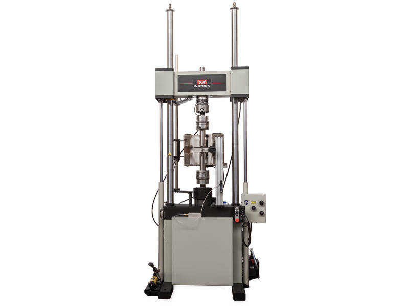
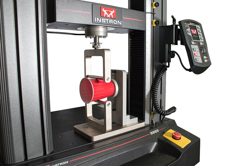
用于金属和复合材料的静态和动态测试

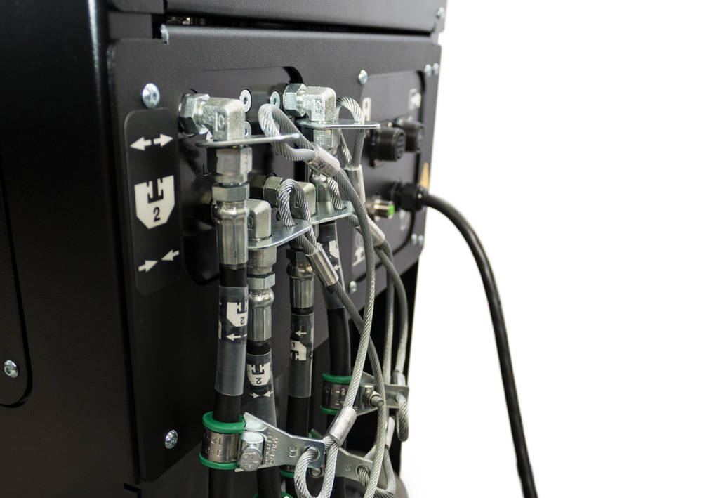
先进液压楔形夹具是一款多功能夹具,可用于静态和动态材料测试应用——动态测试力容量高达 500 kN,静态测试力容量高达 600 kN。 该夹具非常适合金属和复合材料测试,其可互换的夹具钳口可容纳板材或圆棒试样,并且夹具设计可在试样上保持恒定的夹持力,无论施加的测试力如何。 只要有充足的液压供应处于活动并连接状态,夹具就会施加这种受控的夹持力。
工作原理
每个夹具独立运行,外部液压供应提供压力以打开和关闭夹具。 当施加夹持压力时,试样与夹面的相对垂直位置保持不变,以避免夹持过程中试样产生负载。 一旦夹具钳口接触试样,液压就会在夹具头上产生垂直力。 由于该设计会自动补偿试样厚度变化,夹持力将保持恒定。
应用范围

添加试样对中装置(型号 CP135054),以确保您的试样对中一致。 该装置兼容我们先进液压楔形夹具的 2743-401、2742-501 和 2742-601 版本。
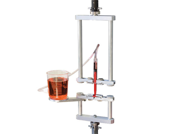
用于静态应变测量
英斯特朗的静态轴向夹式引伸计是一种快速且简捷的应变测量解决方案,适用于塑料、金属材料和复合材料等各种材料。我们数十年的应变测量经验帮助我们优化了这些装置的设计,包括:轻量级坚固交叉撑设计,可消除物理变形导致的误差;内置式保护,可减少装置过度延长造成的损坏;以及经过专门设计的装置臂,只需最小的作用力即可保持附着在试样上,从而最大限度地减少测试期间的刀口滑移。所有的引伸计均符合 ASTM E83 和 ISO 9513 标准,并随附显示每个单元在其出厂校准时的性能表现的校准证书。
2630-100 系列
工作原理
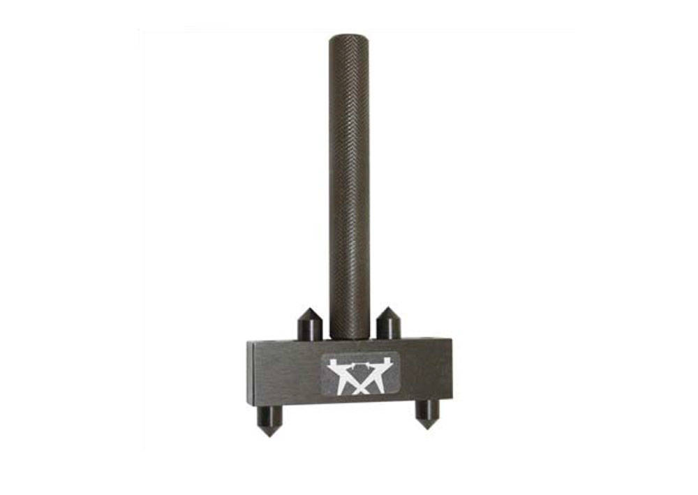
2630 系列引伸计可以进行准确且一致的安装或放置,并且标距长度闭锁装置会在附加后自动释放,从而确保运行的速度和可靠性。这种独特的“锥形闩锁”机构还克服了在开始测试前必须移除销钉或夹子的问题,或在引伸计意外锁定在标距长度时进行测试的问题。
功能与优点
应用范围

| 可用型号 | ||
|---|---|---|
| 目录编号 | 标距长度(公制) | 行程(轴向) |
| 2630-120 | 8 mm | ±50% |
| 2630-101 | 10 mm | ±10% |
| 2630-102 | 10 mm | ±50% |
| 2630-105 | 25 mm | ±10% |
| 2630-106 | 25 mm | +50% |
| 2630-107 | 25 mm | +100% |
| 2630-111 | 50 mm | ±10% |
| 2630-112 | 50 mm | +50% |
| 2630-113 | 50 mm | +100% |
| 2630-123 | 75 mm | +10% |
| 2630-117 | 80 mm | +10% |
| 2630-118 | 80 mm | +50% |
| 2630-119 | 100 mm | +50% |
| 目录编号 | 标距长度(美国惯例) | 行程(轴向) |
| 2630-121 | 0.3 英寸 | ±50% |
| 2630-103 | 0.5 英寸 | ±10% |
| 2630-104 | 0.5 英寸 | ±50% |
| 2630-108 | 1.0 英寸 | ±10% |
| 2630-109 | 1.0 英寸 | +50% |
| 2630-110 | 1.0 英寸 | +100% |
| 2630-114 | 2.0 英寸 | ±10% |
| 2630-115 | 2.0 英寸 | +50% |
| 2630-116 | 2.0 英寸 | +100% |

W-6280 系列
工作原理
这款长标距长度的夹式引伸计采用独特的可拆分式设计,不但可以降低试样断裂过程中发生损坏的几率,还有助于快速连接装备(包括在内)在试样上实现轻松安装。由于其机架尺寸较大,W-6280 系列引伸计需要双手操作才能将仪器安装到试样上,所以这些引伸计仍然依靠销钉来设定标距长度。
应用范围
| 可用型号 | ||
|---|---|---|
| 目录编号 | 标距长度(公制) | 行程百分比(轴向) |
| W-6280-200 | 200 mm | +12.5% |
| W-6280-250 | 250 mm | +10% |
| 目录编号 | 标距长度(美国惯例) | 行程百分比(轴向) |
| W-6280-8 | 8 英寸 | +12.5% |
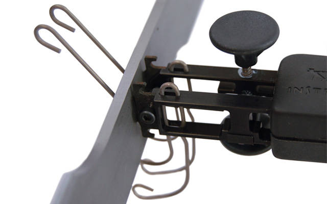
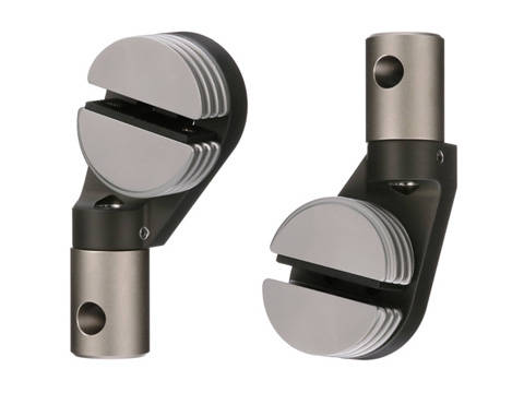
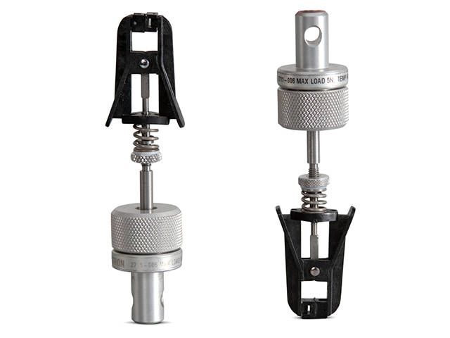
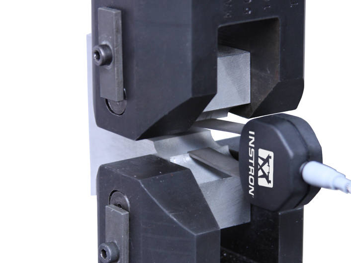
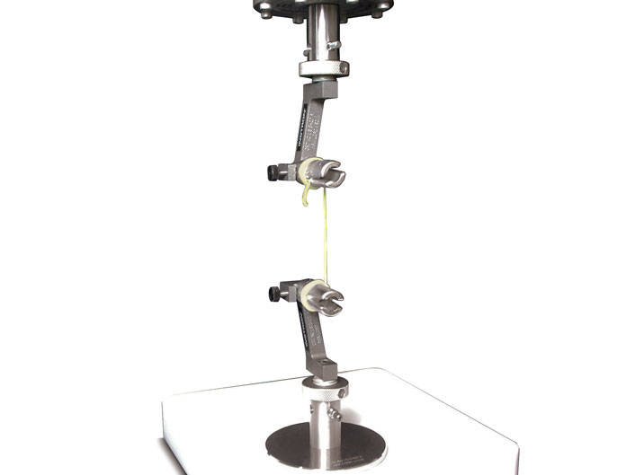
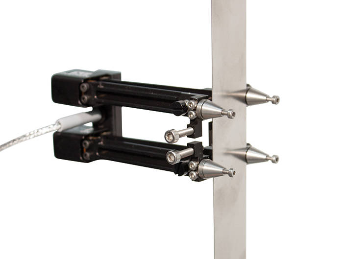
Lever Action Grips and O-Ring Type

Fibers and filaments tend to be relatively thin materials compared to most, but within these types of materials there can be a wide range of thicknesses and tensile strengths that determines the appropriate gripping method. To properly hold onto these materials, Instron offers two types of grips: a lever action style and an O-ring type.
LEVER ACTION GRIPS
Catalog no. 2711-006
The Lever Action Grips provide the ideal means to hold single fiber specimens. The grips are simple, lightweight, and symmetrical in design.
Principle of Operation
Lever Action Grips are generally used for the thicker range of fiber filament specimens. These grips have an adjustable clamping force, self-aligning hard rubber coated faces, and provide ease of operation similar to a clothes pin. An adapter is provided to use the lower grip in the vertical or horizontal orientation to ease specimen insertion.
Application Range
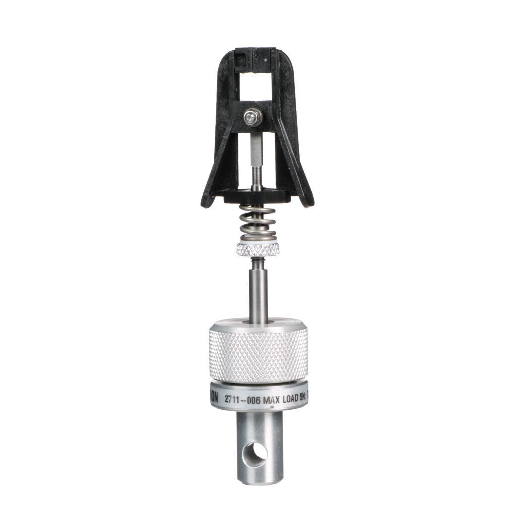
| Specifications | |
|---|---|
| Capacity | 5 N |
| Specimen Diameter | 2.5 mm |
| Temperature Range | -10 °C to 100 °C |
| Upper and Lower Fittings | Type Om (12 mm connection with 6 mm clevis pin) |
| Misc. | Includes a Type A (hook) for the upper grip |

The O-Ring type of grip is designed to hold very small diameter fiber specimens during tension testing. The rubber v-groove provides a gradually increased frictional hold on the specimen and helps reduce grip face pinching and subsequent specimen jaw breaks. Special considerations are built into the design, where the U-shaped bend provides sufficient area for specimen loading.
Principle of Operation
The O-Ring fiber grip utilizes two rubber o-rings sandwiched between two knurled wheels. These wheels thread on a stud and compress the o-rings to achieve desired gripping force on the specimen.
Application Range
| Specifications | |
|---|---|
| Capacity | 0.825 N |
| Specimen Diameter | 1 to 25 microns |
| Temperature Range | -10 °C to 100 °C |
| Upper and Lower Fittings | Type Om (12 mm connection with 6 mm clevis pin) |
| Misc. | Includes a Type A (hook) for the upper grip |
Featuring adjustable clamping pressure and quick-change jaw faces, these grips can be adapted to test a wide variety of specimens.
The grips can also be positioned at 0, 30, and 90 degrees, making them fully compatible with our non-contacting video extensometer products.
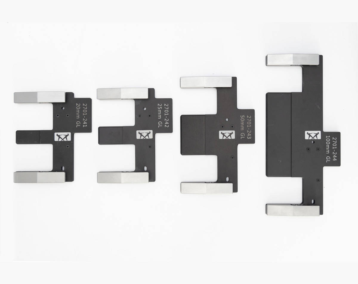
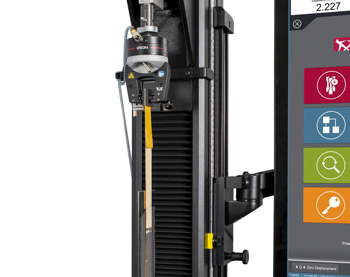
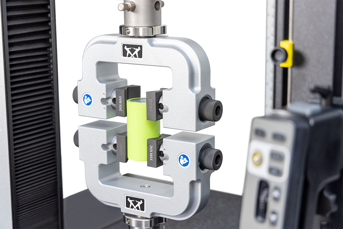
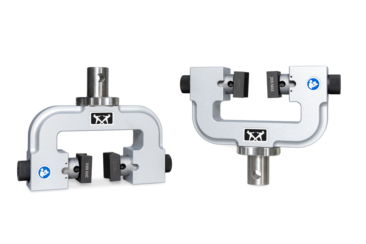
The precision specimen loader improves alignment and the setup process for testing thin films and foils, resulting in reduced variation in test results and improved safety and ergonomics. Available for our 250 N pneumatic side action tensile grips (catalog no. 2712-052), this device uses a detachable alignment clip and linear rail to guide the specimens into the grips. The precision specimen loader is available in multiple sizes to accommodate a wide range of specimen dimensions.
For more information on the importance of specimen alignment for tensile testing of thin films and foils, read our white paper that covers the results of experiments designed to determine the impact specimen alignment has on results.
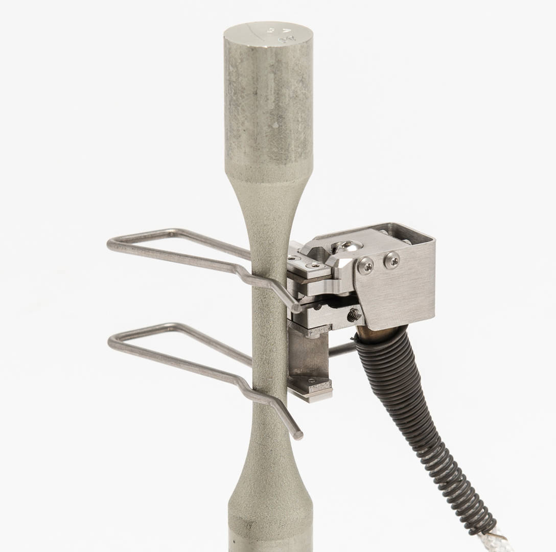
This extensometer can be attached to round and flat specimens to perform tensile, compression, and cyclic tests in environmental chambers up to 600°C with no cooling required. A quick attach kit for mounting on specimens is included. The device has a low operating force that prevents it from affecting the test.
| Specifications | |
| Gauge Length | 25 mm |
| % Travel (Axial) | +50% / - 8.0% |
| Specimen Size (Round) | Up to 15 mm diameter |
| Specimen Size (Flat) | Up to 50 mm wide for specimens up to 6.35 mm thick Up to 19 mm wide for specimens 6.35 mm to 12.5 mm thick |
| Catalog Number | CP118413 |

2632 Series
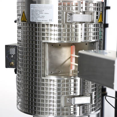
High temperature strain gauge extensometers suitable for use up to 1000°C in a resistance furnace. These extensometers are particularly suited to low cycle fatigue, creep, and stress relaxation testing. The extensometer attaches to a specimen using ceramic wrap-around cord (supplied) or by using a spring type attachment (catalog no. 2632-061). These extensometers are compatible with 3117-150, 3117-152, and 3117-200 furnaces.
| Gauge Length | % Travel (Axial) | Chisel and End Rods | Catalog No. |
| 12.5 mm | +20% / -10% | Quartz | 2632-054 |
| 12.5 mm | +20% / -10% | Alumina | 2632-055 |
| 25 mm | +10% / -5% | Quartz | 2632-056 |
| 25 mm | +10% / -5% | Alumina | 2632-057 |

E-Series
The E-Series high temperature extensometer is a self-supporting, side-entry axial strain gauge designed for use in furnaces with a slot for extensometers or with an induction heating system. The device uses a ceramic fiber cords to attach the extensometer to the specimen.
| Gauge Length | % Travel (Axial) | Catalog No. |
| 25 mm | ± 20% | W-E418-25 |
| 50 mm | ± 20% | W-E418-50 |
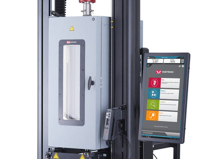
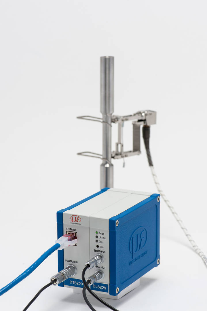
非接触式高级视频引伸计

Instron 的高级视频引伸计 AVE2 除了在静态测试中表现出色外,现在还可用于循环试验和高速单调测试测量。这款轻便的非接触式引伸计设计精巧,便于在不同系统间轻松切换,可在实验室内快速移动,为希望在不接触试样的情况下研究材料动态行为的科研人员、工程师和质量专家提供了极大的灵活性。
优化的动态测试能力


采用非接触式动态应变控制和测量技术
探索更多可能

高级的非接触式解决方案
这种非接触式引伸计最大程度地减少了测试环境和操作人员的影响,防止试样过早断裂,从而获得更加一致、准确和可重复的数据。
防衍射气流系统
典型的实验室环境会受到气流变化的影响,从而产生高达几微米的误差。因此,为了最大限度地提高测试精度,AVE2 采用了获得专利的 CDAT 风扇,可在试样和相机之间产生稳定的层流气流,即使在测试过程中空调处于运行状态,也能在自由场空间中产生一致的结果。


交叉偏振照明系统
不同的实验室有不同的光照条件,而且随着时间的推移,同一房间的光照水平也会发生变化,这种差异会导致同一类型的试验结果出现差异。为了确保 AVE2 看到的图像是一致的,Instron 开发了获得专利的交叉极化照明系统,该系统能够在不同实验室光照条件下均实现可重复的试验结果。
全集成的解决方案
该解决方案能够长期稳定地提供所需的测试结果,同时也能适应实验室不断变化的需求。该系统兼容多种环境箱、水浴槽、可选配镜头和附件,且都可通过我司专有测试软件解锁,因此其潜在的测试应用几乎是无限的。

前瞻性动态性能技术
适用于多种循环与单调测试
与夹持式引伸计等传统替代产品相比,AVE2 的灵活性和可用性都得到了提高,除了拉伸和压缩试验外,AVE2 还能便捷测量和控制各种材料和试样几何形状的循环应变。现在,您仅需实验室中的一台设备,就能测量多种规格长度和不同伸长率的试样。
高级的的视频引伸计 AVE2 可与一系列
Instron 动态疲劳试验系统配合使用


ElectroPuls® 全电子
动静态疲劳试验系统
通用型
电液伺服疲劳系统
资讯


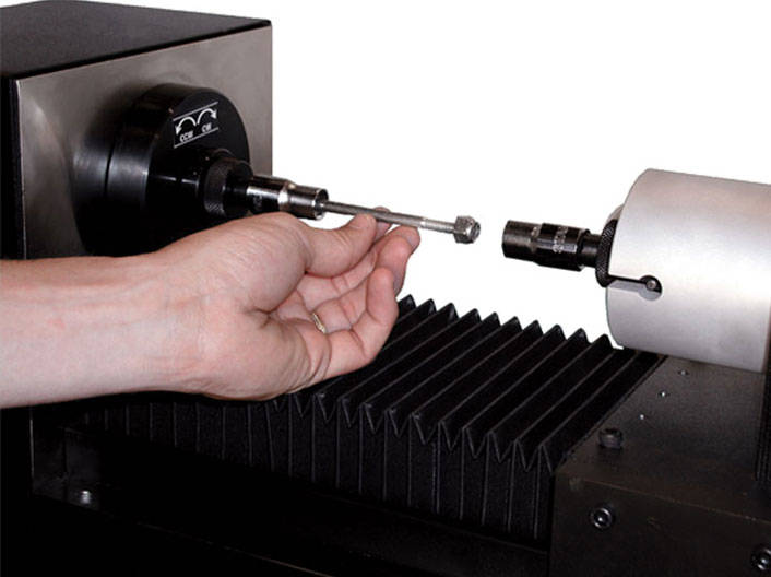
工作原理
AutoX750 与 Instron 的 3360、3380、3400、5500、5960、5980 和 6800 系列电子万能材料试验系统以及 LX、DX、HDX 和 KPX 静态液压试验系统集成,并通过 USB 接口由 Bluehill® Universal 测试软件控制。该软件提供易于使用的试验序列和设置,有助于在试验前后自动调整标距、参考臂位置以及臂的打开和关闭。
测量臂采用平衡技术,几乎无重量,因此可消除对被测材料性能的影响。测量臂由电机驱动,每次均可自动定位至正确位置及标距长度。
应用范围

AutoX750 的高精度和长行程使其成为理想的引伸计,可适用于包括金属、塑料和复合材料在内的所有材料
可以测定各种计算结果,包括模量、偏置屈服、断裂塑性伸长率(非比例伸长)以及板材的 r 和 n 值。
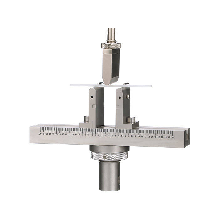
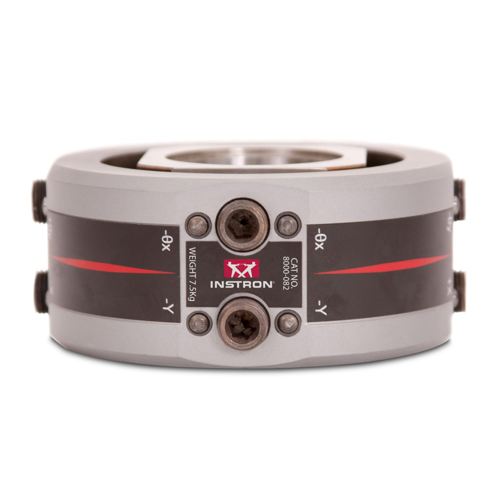
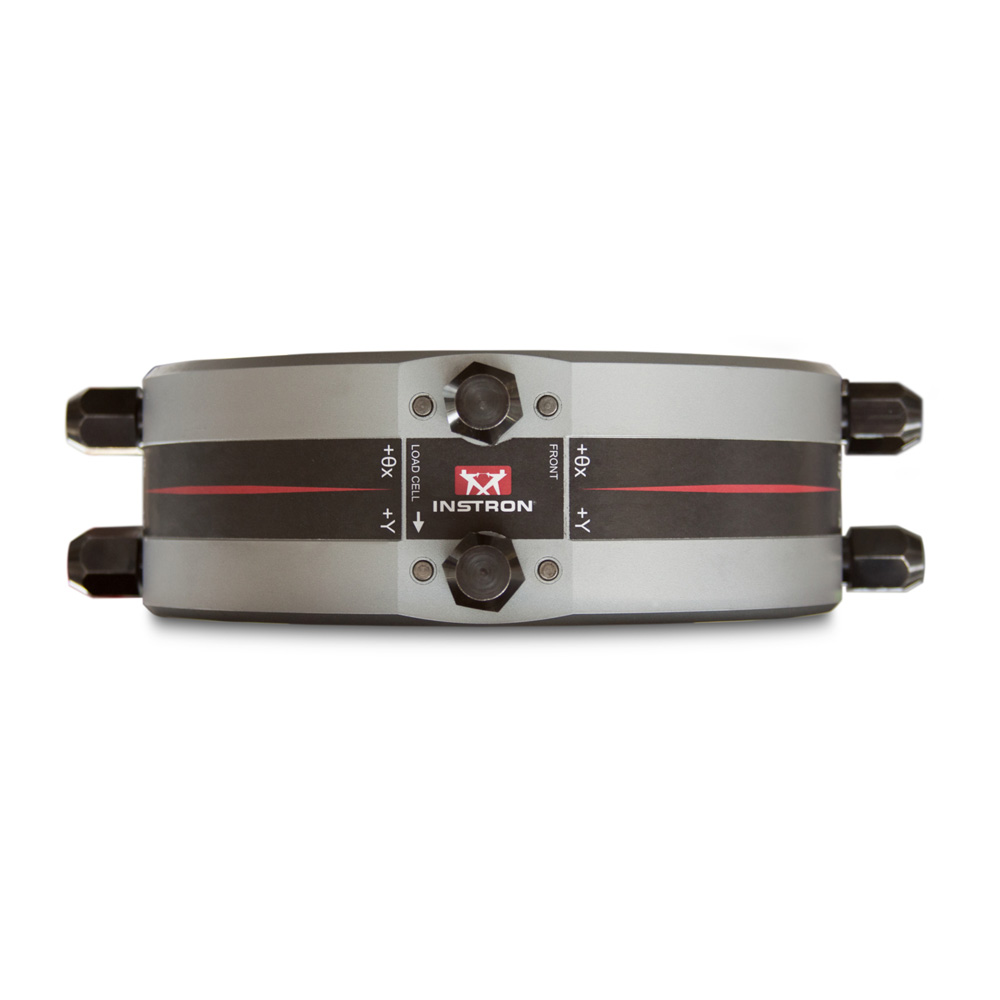
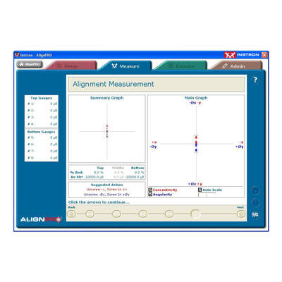
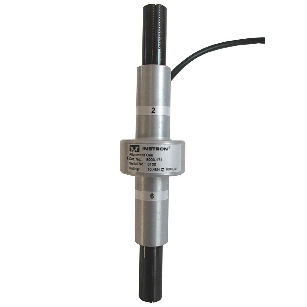
对于有特定对中要求的应用,AlignPRO 系统可用于控制加载链的同心度和角度,从而优化对中效果。该系统包括一个安装在载荷传感器与横梁之间的 AlignPRO 工装,用于调整同心度和角度偏差。AlignPRO 软件可监测安装在平面或圆形对中单元上的应变片输出信号。通过这些输出数据计算因角度误差和同心度误差导致的弯曲变形,操作人员可在 AlignPRO 软件中实时监测弯曲变化效果的同时,通过对中装置进行精确调整。
| 规格 | |
| 目录编号 | 说明 |
| 2910-130 | 用于 100 kN(22 kip)电子万能材料试验系统 |
| 2910-132 | 用于 150 和 250 kN(34 和 56 kip)电子万能材料试验系统 |
| 8000-082 | 用于疲劳系统 - 最大载荷范围至 250 kN (56 kip) |
| 8000-084 | 用于疲劳系统 - 最大载荷范围至 500 kN (112 kip) |
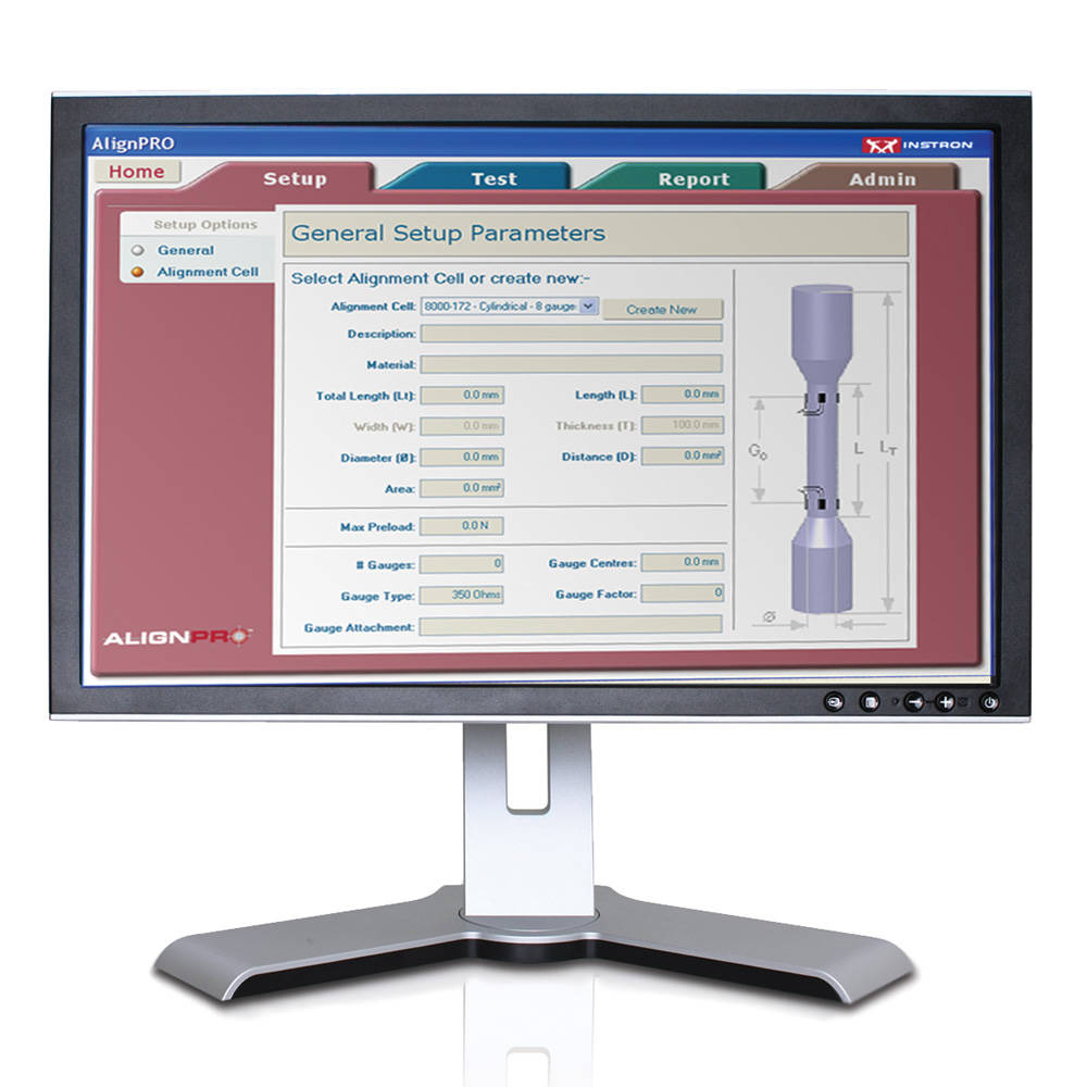

| 规格 | |
| 目录编号 | 说明 |
| 8000-171 | 含应变片的对中试样,8 组应变片,直径 8 mm |
| 8000-172 | 含应变片的对中试样,8 组应变片,直径 10 mm |
| 8000-173 | 含应变片的对中试样,8 组应变片,平板 12 mm x 6 mm |
| 8000-174 | 含应变片的对中试样,8 组应变片,平板 15 mm x 2 mm |
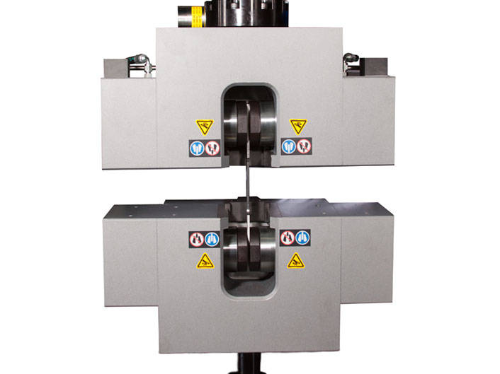
配有获得专利的自对中机械同步结构

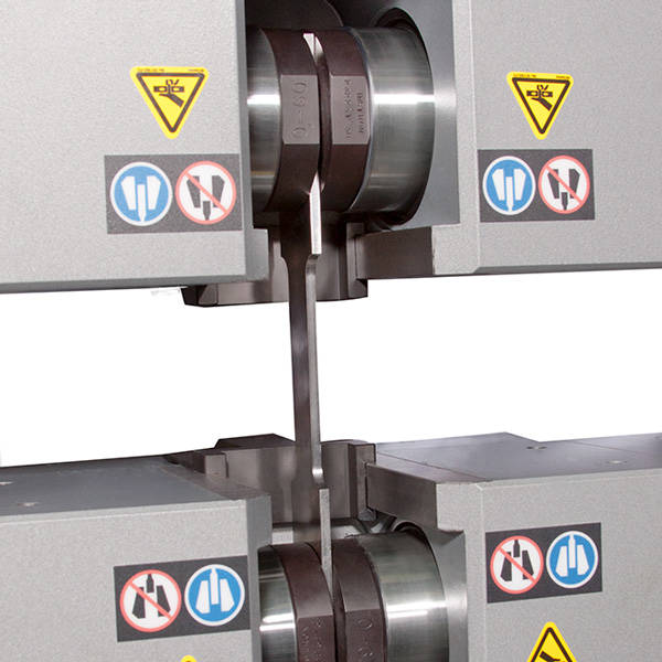
Instron 液压平推夹具为大载荷测试提供一种创新的解决方案。与传统的夹具设计相比,它具有更卓越的夹持性能、可用性和操作员安全性。该类夹具可在试样上保持恒定的夹持力,该夹持力垂直于测试方向,不会对拉伸载荷产生影响。

Instron 双面平推夹具采用了最新的 DuraSync 技术。与市场上常见的液压或机械齿轮设计相比,这种自对中机械同步结构有诸多改进。
特点
应用范围
| 规格 | ||||||
|---|---|---|---|---|---|---|
| 目录编号 | 力容量 | 平推类型 | 试样尺寸范围 | |||
| 圆棒 | 板材 | 电缆 | ||||
| W-5450 | 250 kN | 双面平推 | 标准 | 3 - 60 毫米 | 0 - 60 毫米 | - |
| W-5400 | 600 kN | 单面平推 | 标准 | 3 - 57 毫米 | 0 - 75 毫米 | - |
| W-5410 | 600 kN | 双面平推 | 标准 | 3 - 60 毫米 | 0 - 100 毫米 | - |
| W-5420 | 600 kN | 双面平推 | 高级 高级型号
高级夹具可用于测试标准板材、圆棒、钢绞线和电缆试样。该型号也可配置用于“过零 ”测试,前提是机架能够承受过零(循环)载荷。 |
3 - 60 毫米 过零试样范围:3 - 60 mm | 0 - 100 毫米 过零试样范围:0 - 75 mm | 4.8 - 25.4 毫米 |
| W-5460 | 1000 kN | 双面平推 | 高级 高级型号
高级夹具可用于测试标准板材、圆棒、钢绞线和电缆试样。该型号也可配置用于“过零 ”测试,前提是机架能够承受过零(循环)载荷。 |
3 - 85 毫米 | 0 - 120 毫米 | 4.8 - 25.4 毫米 |
| W-5430 | 1500 kN | 双面平推 | 高级 高级型号
高级夹具可用于测试标准板材、圆棒、钢绞线和电缆试样。该型号也可配置用于“过零 ”测试,前提是机架能够承受过零(循环)载荷。 |
3 - 85 毫米 过零试样范围:3 - 85 mm | 0 - 120 毫米 过零试样范围:0 - 85 mm | 4.8 - 25.4 毫米 |
| W-5440 | 2000 kN | 双面平推 | 高级 高级型号
高级夹具可用于测试标准板材、圆棒、钢绞线和电缆试样。该型号也可配置用于“过零 ”测试,前提是机架能够承受过零(循环)载荷。 |
3 - 100 毫米 过零试样范围:3 - 85 mm | 0 - 120 毫米 过零试样范围:0 - 85 mm | 4.8 - 25.4 毫米 |

气动夹具用气动控制套件
可选配气动控制装置、脚踏开关或气路分配套件,以方便夹具闭合并提高测试效率。

液压夹具泵
Instron 的液压夹具泵旨在为大载荷测试应用提供精确可靠的夹持力,载荷范围高达 600 kN。

机架用试验台 / 底座
机架用试验台或底座可加装于落地式或台式万能试验系统系统中,以将测试空间调整至更符合操作员人体工学的高度。

碎片防护装置
碎片防护装置在测试空间与操作人员之间形成一道防护屏障。对于在测试过程中可能发生剧烈破坏的材料,如复合材料、钢筋和电缆,这类防护屏障是必要的。

当今的测试实验室和制造商有各种各样的材料和部件测试需求,为了满足这些不同的需求,Instron 提供了不同配置的设备,以确保为测试应用提供正确的解决方案。

电脑硬件
对于使用计算机的系统,需配备电子接口。采用 GPIB 通信的系统,则要求计算机配备适配的接口卡。
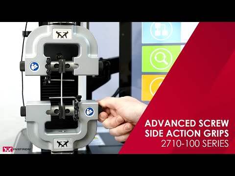
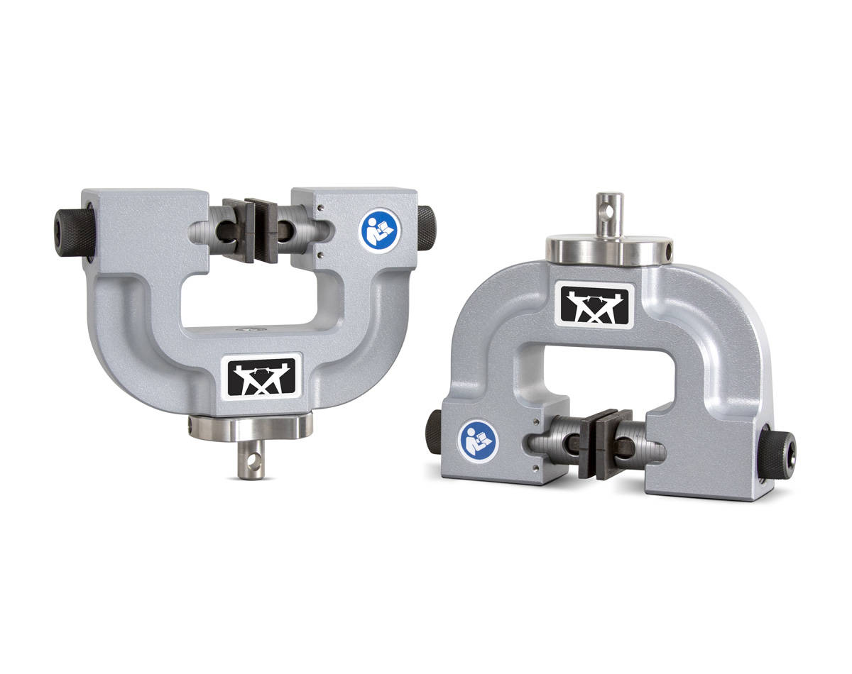
适用于各种材料和试样类型的拉伸试验

手动平推夹具应用广泛,可简单有效地夹持试样。通过双面平推设计,可以调整夹具开口以适应不同的试样厚度,确保试样受力和夹具体在同一轴线上。夹具可以配备各种尺寸的可替换夹面,并可以选择金属光面、橡胶涂层和锯齿等各种表面形式。
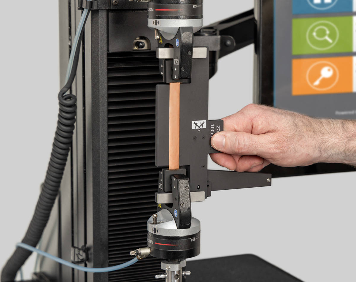
2710-100系列| 100 N-10 kN载荷容量
2710-100系列双面平推设计可适用于最大46 mm(1.8 in)厚的试样,对不规则或非对称试样(例如搭接剪切和元件测试)进行补偿。夹具两侧的旋钮上都有滚花,便于手动拧紧,更高载荷的夹具还具有内六角螺钉旋钮,可使用六角扳手或扭矩扳手拧紧试样。夹具上带有刻度,有助于试样居中。
| 载荷容量选项 | 目录编号 |
|---|---|
| 100 N | 2710-111 |
| 500 N | 2710-112 |
| 1 kN | 2710-113 |
| 2 kN | 2710-114 |
| 5 kN | 2710-115 |
| 10 kN | 2710-116 |
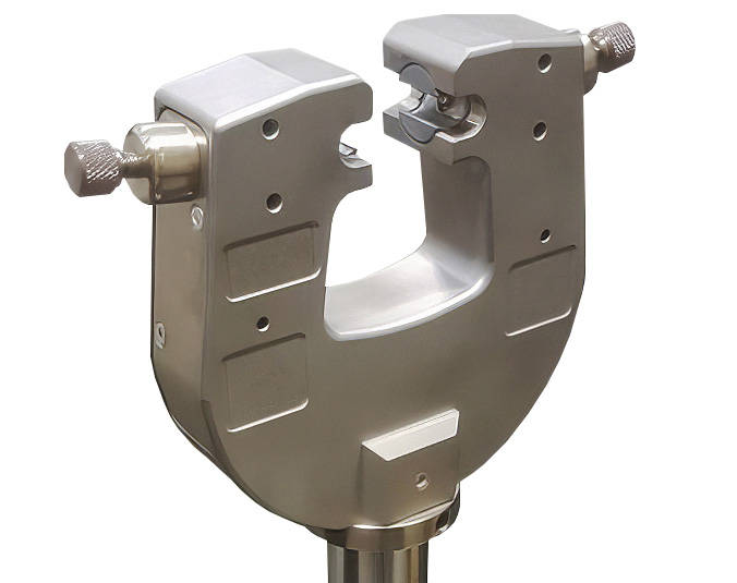
高级手动平推夹具

快速更换夹面
快速更换夹面,在不使用工具或销钉的情况下,几秒钟内单手即可更换所有夹面。
简化对中
夹具上带有刻度,便于试样对中。自对中夹面可补偿试样的不规则性。选配的试样对中装置帮助试样对中定位,以提高测试结果的重复性。
通用性
大开口,适用于各种厚度的试样和部件。夹面和夹具体之间的空间较大,便于试样装夹。
夹面类型
供应橡胶涂层、锯齿、金属光面、高摩擦(HFC)、线接触、波纹和V型夹面。
其他型号
中小载荷夹具
适用于多种材料和试样类型的拉伸试验

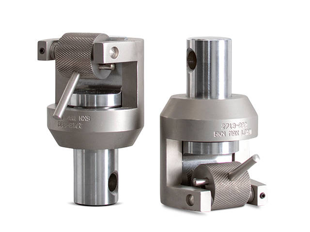
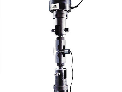
手动楔形夹具便于试样夹持、对中和定位。夹持样品后,夹持力随着试验载荷的增加而增加。夹具设计为夹具体动,而夹面不动,在试样夹持过程中几乎不会产生预加载,特别适用于测试金属和复合材料等高强度材料,确保试样不打滑。
1 kN - 150 kN 载荷范围
工作原理
这类夹具的楔形作用原理使它们夹紧试样的同时,不会改变夹面相对于试样的垂直位置。这是通过移动夹具主体以闭合夹面的设计实现的。此功能使得可以预先选择特定的点,在该点上以一致的夹面间距夹持试样,并且不会施加可能导致试样屈曲的压缩力。
通过自紧式机构可为难以夹持的材料提供可靠的夹持力。夹面和夹具通过弹簧连接,并通过安装在传动轴上的挡块确保夹面处于固定位置不会在轴向上移动。当夹持试样时,夹具体向上移动的过程中,给夹面一个侧向力,确保夹面水平移动,夹持试样。
夹具采用前部开放式设计,便于更换夹面和夹持试样。由于夹面处于固定位置,在试样破坏时不会产生反冲或松动,如果连接了引伸计,引伸计也将保持在原位。


优势
应用范围
| 适用型号 | ||
|---|---|---|
| 载荷容量 | 最大试样宽度 | 目录编号 |
| 1 kN | 19 mm | 2716-016 |
| 2 kN | 19 mm | 2716-017 |
| 5 kN | 25 mm | 2716-010 |
| 30 kN | 25 mm | 2716-015 |
| 30 kN [高温] | 25 mm | 2736-015 |
| 50 kN | 25 mm | 2716-020 |
| 100 kN | 25 mm | 2716-002 |
| 100 kN | 50 mm | 2716-003 |
| 100 kN [高温] | 25 mm | 2736-004 |
| 100 kN [高温] | 50 mm | 2736-005 |
| 150 kN | 50 mm | 2716-008 |
主要用于薄板、薄膜、柔性塑料、橡胶和弹性体的拉伸试验

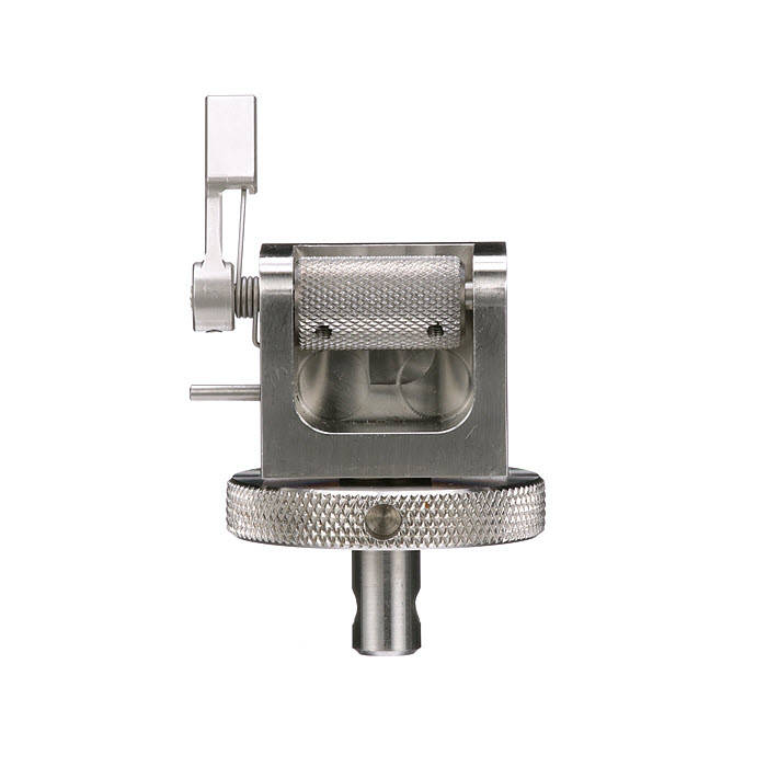
自紧式偏心辊拉伸夹具主要用于对弹性体和其他柔性材料进行精密测试,这些材料在受力时横截面积会大幅缩小。该夹具具备卓越的测试精度、可靠的防滑夹持操作,且操作简便快捷。上夹具采用平衡设计,可使试样与载荷传感器对中,从而消除非轴向力。
1 kN - 5 kN 载荷范围
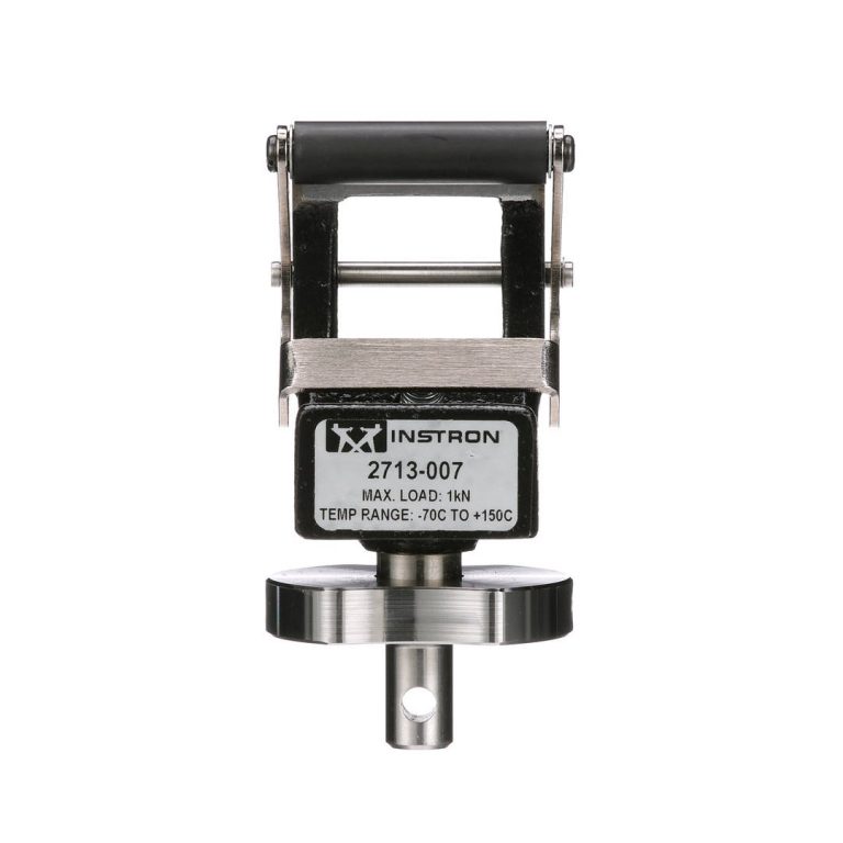
1-kN-Modell | 2713-007
2-kN-Modell | 2713-004

5-kN-Modell | 2713-002
自紧式偏心辊拉伸夹具采用偏心辊夹紧机构。单手快速操作减少了加载试样所需的时间。试样插入极为简便,滚轮支架的弹簧压力提供了正向防滑夹持力。该夹持力足以在施加载荷前固定试样。在试验过程中,辊的后续动作可防止试样在载荷增加时从夹具中滑出。
试样载荷:1 kN 夹具
试样载荷:2 kN 夹具
自紧式偏心辊拉伸夹具

快速插入试样,提高测试效率。
主动的防滑夹持操作,可获取准确的结果。
在施加作用力时,偏心辊的夹持操作会增加夹持力。
专为在 -70° C 至 315° C(-94° F 至 600° F)的温度范围内使用而设计。
小载荷夹具

2713-006 系列 | 100 N 载荷范围
这些夹具是天然乳胶、弹性体、纸张和聚合物薄膜进行拉伸试验的理想之选。
2620系列引伸计设计用于金属、复合材料、塑料、木材和其他材料总应变高达原始标距的±50%。可浸入各种液体(丙酮、矿物油和硅油、酒精和类似的冷却/加热流体)中,并且可以快速轻松地校准。
| 名称 | 标距 | %行程(轴向) | Cat# |
| 动态引伸计 12.5mm GL ±5mm 行程 | 12,5 ; 25和50mm | ±40, ±20和±10% | 2620-601 |
| 动态引伸计 12.5mm GL ±2.5mm 行程 | 12,5 ; 25和50mm | ±20, ±10和±5% | 2620-602 |
| 动态引伸计 10mm GL ±1mm 行程 | 10, 25和50mm | ±10, ±4和±2% | 2620-603 |
| 动态引伸计 25mm GL +12.5mm -2.5mm 行程 | 25和50 mm | +50 à -10和+25 à -5% | 2620-604 |

2620 系列动态应变片式拉伸计是精确的轻型设备,用于直接测量和闭环控制各种静态和高频循环材料测试应用中的应变。使用 2620 系列动态应变片式拉伸计可进行拉伸、压缩、低和高循环疲劳测试、蠕变和应力松弛以及直线(斜坡)测试,符合各种国家和国际标准。
2620 系列拉伸计设计用于金属、复合材料、塑料、木材和其他材料,其总应变可达原始测量长度的 ±50%。它们可浸入各种液体(丙酮、矿物油和硅油、酒精和类似的冷却/加热液体)中,并可快速、轻松地进行校准。
| 项目名称 | 检具长度 | % 行程(轴向) | 型号 |
| 动态拉伸计 12.5 毫米 GL ±5 毫米行程 | 12.5;25 和 50 毫米 | ±40、±20 和 ±10 | 2620-601 |
| 动态拉伸计 12.5 毫米 GL ±2.5 毫米行程 | 12.5;25 和 50 毫米 | ±20、±10 和 ±5 | 2620-602 |
| 动态拉伸计 10 毫米 GL ±1 毫米行程 | 10、25 和 50 毫米 | ±10、±4 和 ±2 | 2620-603 |
| 动态拉伸计 25mm GL +12.5mm -2.5mm 行程 | 25 和 50 毫米 | +50 à -10 和 +25 à -5 | 2620-604 |
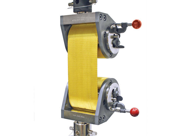
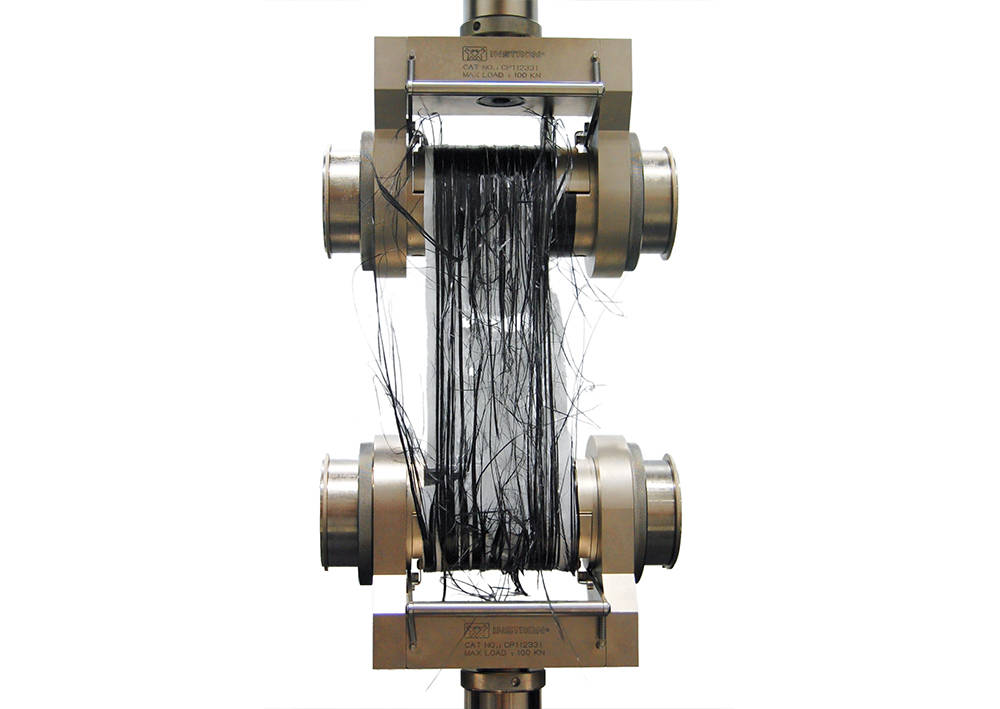
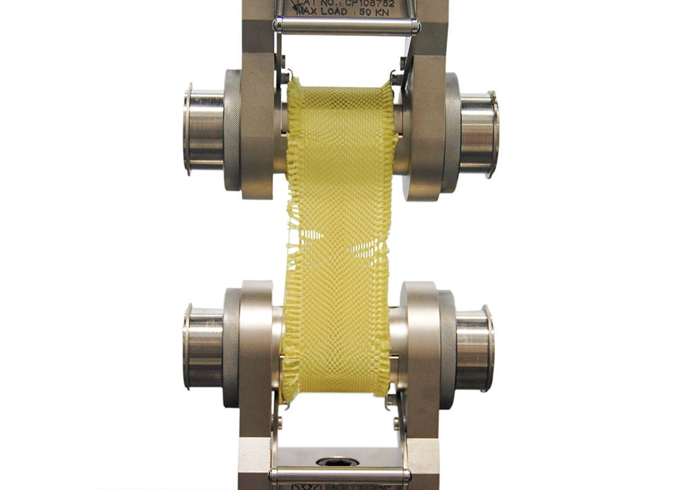
For Testing High Strength Textile Materials

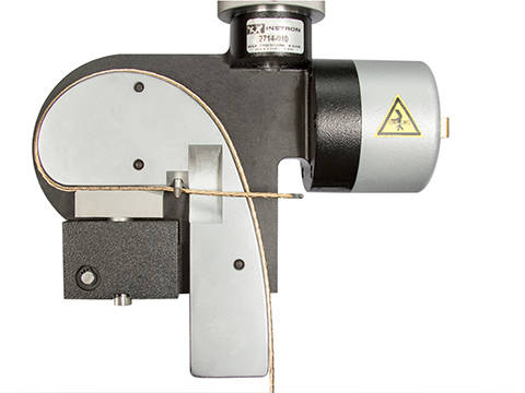
Webbing capstan grips are designed to permit faster, easier testing of seat belts and other high strength belts and tapes. Based on the capstan principle, these grips minimize slippage and jaw breakage effects, and permit the predetermination of specimen length while allowing for quick, convenient loading.
These webbing capstan grips incorporate an ingenious double capstan design which provides fast, easy loading with a gripping action that results in proper breaks in the full gauge length of the specimen. The key to the ease of loading is the use of an inner and outer capstan. The specimen is loaded simply by inserting one end into the groove of the inner capstan and cranking it through 360 degrees. Gripping efficiency is also greatly increased because the surfaces of both capstans are utilized.
| Specifications | |
|---|---|
| Catalog no. | 2715-003 |
| Capacity | 50 kN |
| Standards | ASTM D6775, D3950 |
| Maximum Specimen Width | 50.8 mm |
| Maximum Specimen Thickness | 4.75 mm |
| Temperature Range | -29 °C to 121 °C |
| Upper and Lower Fittings | Type Dm (1.25 in connection with 1/2 in clevis pin). Rigid coupling required. |
| Brochure | Download |
Translation and clamping stages are used to precisely position and align a test specimen below the actuator. These are commonly used for securely positioning microelectronic circuit boards and components within the testing system.
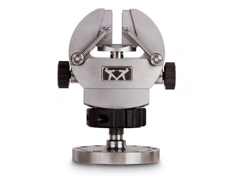
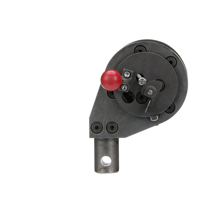
用于测试纤维、绳、纱线和精细编织线

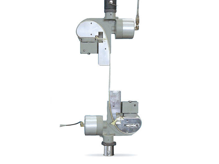
气动绳线夹具为夹持纤维、绳、纱线和细编织线提供了一种便捷的方式,可减少测试时相关材料在钳口处断裂的问题。 一款经过特殊设计的夹头,表面光滑且带有渐变凸轮的曲面轮廓,便于试样装夹,同时可减少试样夹持区域的应力。夹持机器既可以自动启动,也能通过脚踏开关操作。这使得装夹操作无需用手固定夹具,操作人员能用双手轻松装夹试样。气动绳索和纱线夹具可提供可选择的夹持力,以适应不同材料,并且具有出色的随动性能,能够补偿因试样蠕变导致的夹持力衰减。
如果单丝、帘线和纱线的夹持面积相对于强度而言较小,使用常规的夹面通常会导致试样断在夹持处。气动绳索和纱线夹通过摩擦力将夹持力均匀地分布的半绞盘弧面上,从而克服试样提前失效的问题。
此外,施加在试样端部的气动缓冲夹持力可补偿由于试样蠕变引起的夹持力衰减。气动装置激活活动夹块,作用于固定的渐开线夹块上。由此起到绞盘的作用,为试样提供支撑,使试样从自由应力长度逐渐过渡到夹持端,最大程度地减少了试样断在夹面处的可能性。绞盘还装有抛光的导向角,有助于快速加载试样。抛光的表面可防止试样装夹过程中损坏单根纤维。
将试样放置在导向角的顶部,并向下滑动到夹持位置。通过气动脚踏开关可关闭或打开气动夹具,无需双手操作。还可以通过软件或系统默认设置,使用自动气动控制套件解放双手,实现自动和预拉伸测试。
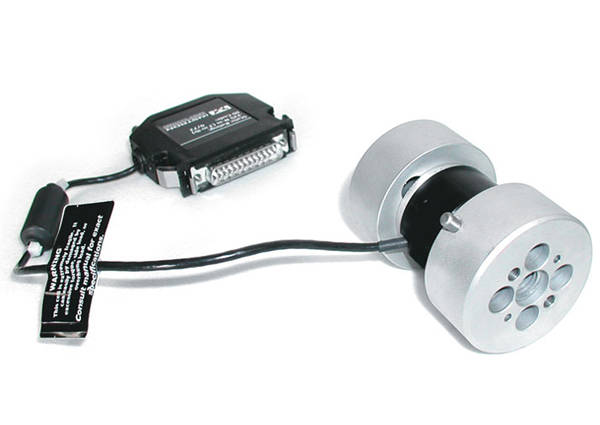
Dynacell 是世界上第一个真正意义上的动态载荷传感器,自设计之初便专为动态载荷测量而打造。Dynacell 在载荷传感器的核心位置 - 轴心安装了加速度计。这一设计消除了因偏心加载而导致加速度读数出现误差的风险。

2527 系列双轴 Dynacell 载荷传感器
2527 系列载荷传感器专为动态疲劳试验系统设计;性能卓越,能够测量的最小力值范围至传感器满量程的 1/250,测量精度可达读数的 0.5%。

2527 系列 Dynacell 载荷传感器
Dynacell 是一种独特的载荷测量装置,可自动补偿因加载链部件惯性而引起的载荷误差。对于所有形式的动态测试而言,动态惯性补偿方法是必不可少的。
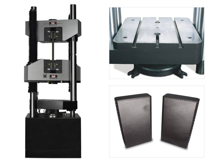
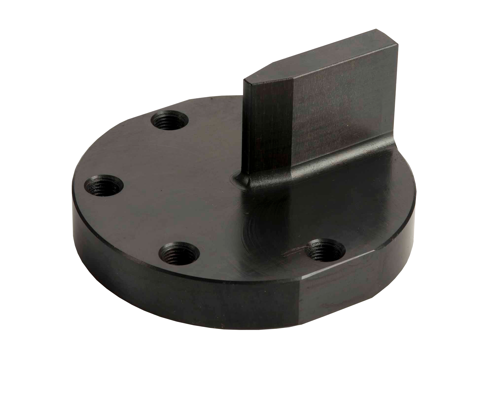
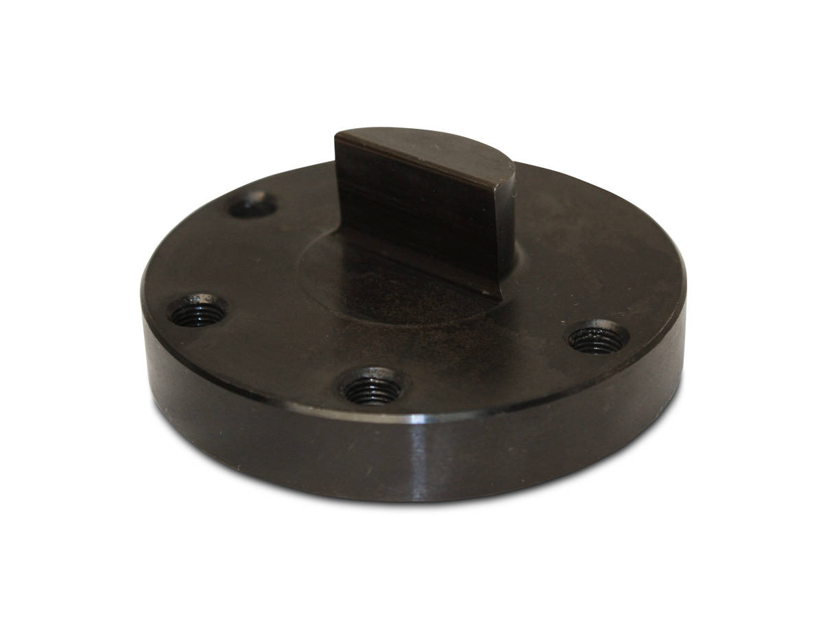
用于测试部件和结构件

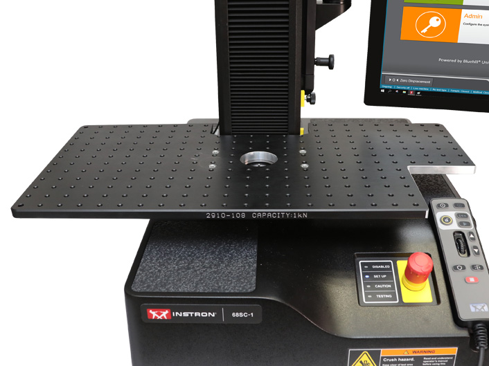
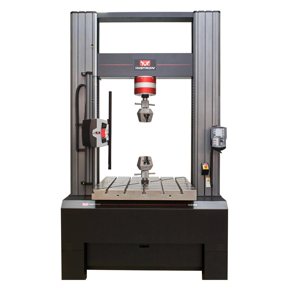
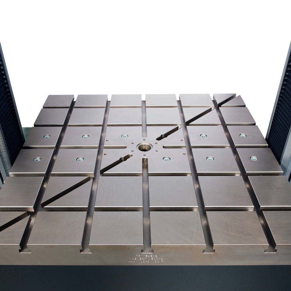
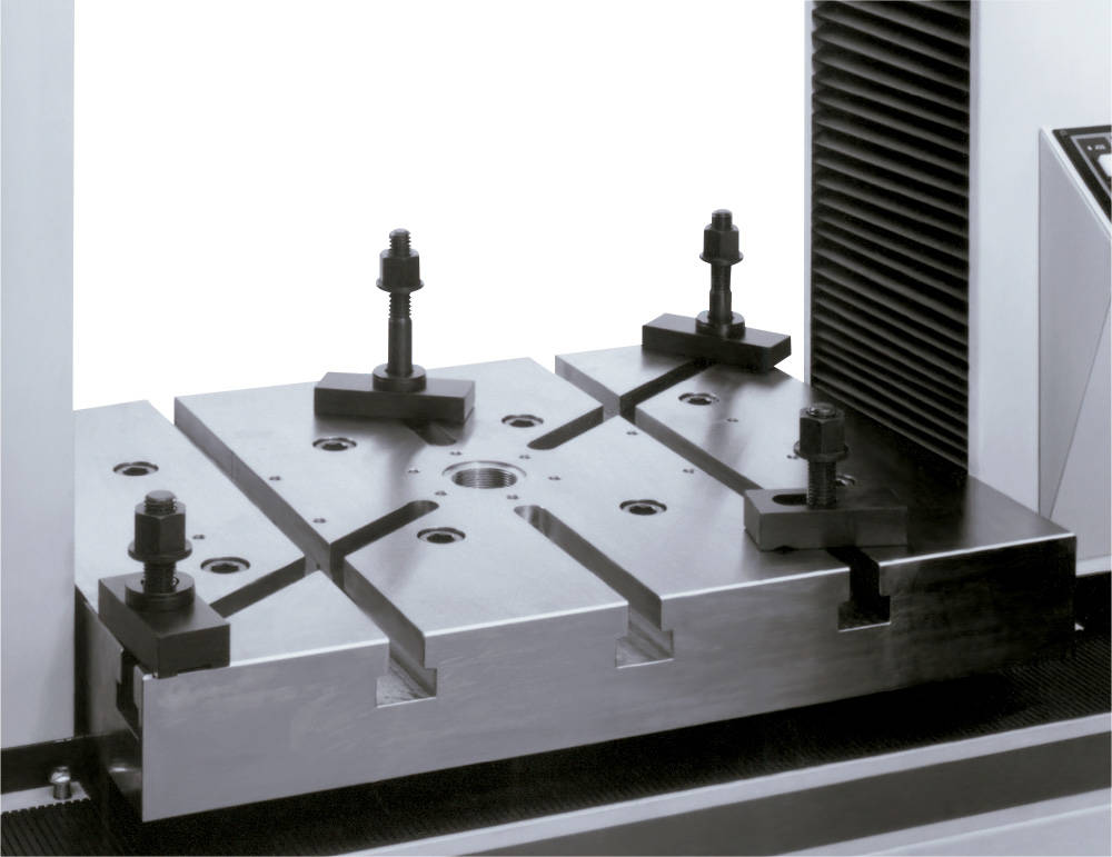
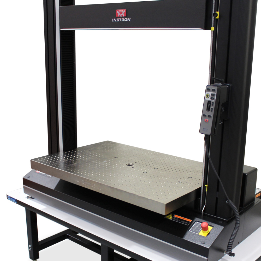
T 型槽平台为电子万能试验机提供了扩展的工作区域,使得用户在进行拉伸、压缩和弯曲测试时,能够更方便地固定部件及结构件。T 型槽平台直接安装在机器底座上,并配备了 T 型槽,该槽可提供样品前后、左右及斜对角线安装方向。然后就可以使用所附的各种夹具将部件和结构件固定在平台的适当位置。借助这种设计,您可以使用标准的 Instron 夹具、测试工装和其他主要配件,无需从机架中移除 T 型槽平台。

T 型槽平台使用户能够使用非标的夹具固定在电子万能试验机上。外购的 T 型槽螺母可先滑入平台的倒 T 型槽。然后可将螺栓、螺柱或螺杆旋拧到螺母中。T 型槽平台可用于固定试样,否则在受力情况下可能会滑出实验区域。
T 型槽平台也可用于将试样放置在同一位置,以实现重复测试和批量测试。可将导轨、滑块或止动器放置在平台上,并用螺栓固定在相应位置,以便在每次测试中精确放置试样。

| 规格 | ||||
|---|---|---|---|---|
| 目录编号 | 最大载荷容量 | 兼容机架 | 宽度 | 深度 |
| CP103964 | 5 kN | 3340、4440、5540、5840、5940、34SC、68SC 单立柱系统 | 200 毫米 | 160 毫米 |
| 2850-206 | 50 kN | 3360 台式试验系统 | 400 毫米 | 500 毫米 |
| 2850-205 | 50 kN | 4460、5560、5860、5960、34TM、68TM 台式试验系统 | 400 毫米 | 500 毫米 |
| 2850-203 | 300 kN | 3382、3384、3385H、34FM-100、34FM-300、4481、4482、4484、4485、5581、5582、5584、5585、5585H、5881、5882、5884、5885、5885H、5982、5984、5985、68FM-100、68FM-300 | 550 毫米 | 500 毫米 |
| 2850-202 | 600 kN | 载荷超过250kN的4400、5500、5800、5900 落地式试验系统 | 640 毫米 | 640 毫米 |
This composite tensile grip guide provides an overview of key specifications for tensile grips that are ideally suited for testing composite materials. For a detailed look at the requirements and important issues related to gripping composite laminate coupons, read our Composites Gripping Guide White Paper.

| Manual Wedge Action Grips | |
| Grip Type | Moving body wedge |
| Static Capacity | 100 kN, 150 kN |
| Operation | Manual |
| Interchangeable | Yes |
| Temperature Range | -70° to 315° C |
| Can You Attach Fixtures Without Removing Grips? Some grips can be outfitted with adaptors to attach other fixtures - offering the flexibility to perform other tests without needing to remove the grips. This is referred to as piggybacking. |
No |
| Nadcap Alignment | No |
| Catalog Numbers | 2716-002, 2716-003, 2716-008, 2736-004, 2736-005 |

| Precision Manual Wedge Grips | |
| Grip Type | Moving body wedge |
| Static Capacity | 100 kN, 250 kN |
| Operation | Manual |
| Interchangeable | Possible (not easy) |
| Temperature Range | -80° to 250° C |
| Can You Attach Fixtures Without Removing Grips?  Some grips can be outfitted with adaptors to attach other fixtures - offering the flexibility to perform other tests without needing to remove the grips. This is referred to as piggybacking. |
Yes |
| Nadcap Alignment | Yes |
| Catalog Numbers | 2716-028, 2716-030 |

| Hydraulic Wedge Action Grips | |
| Grip Type | Moving body wedge |
| Static Capacity | 130 kN, 312 kN, 600 kN |
| Operation | Hydraulic |
| Interchangeable | No |
| Temperature Range | Ambient only |
| Can You Attach Fixtures Without Removing Grips?  Some grips can be outfitted with adaptors to attach other fixtures - offering the flexibility to perform other tests without needing to remove the grips. This is referred to as piggybacking. |
Yes |
| Nadcap Alignment | Yes |
| Catalog Numbers | 2743-401, 2742-501, 2742-601 |

| Extended Hydraulic Wedge Grips | |
| Grip Type | Extended moving body wedge |
| Static Capacity | 130 kN, 312 kN |
| Operation | Hydraulic |
| Interchangeable | No |
| Temperature Range | -70° to 350° C |
| Can You Attach Fixtures Without Removing Grips?  Some grips can be outfitted with adaptors to attach other fixtures - offering the flexibility to perform other tests without needing to remove the grips. This is referred to as piggybacking. |
Yes |
| Nadcap Alignment | Yes |
| Catalog Numbers | CP104947, CP109120 |

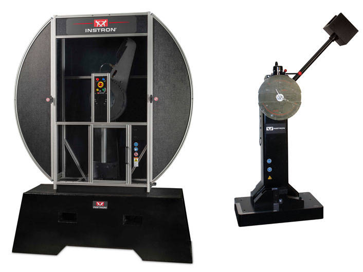
Hammer weights and attachment hardware for use with MPX Series frames of equal or greater capacity.
| Description | Catalog No. |
| 300J Hammer Weight | W-3576-A |
| 450J Hammer Weight | W-3576-B |
| 600J Hammer Weight | W-3576-C |
| 750J Hammer Weight | W-3576-D |
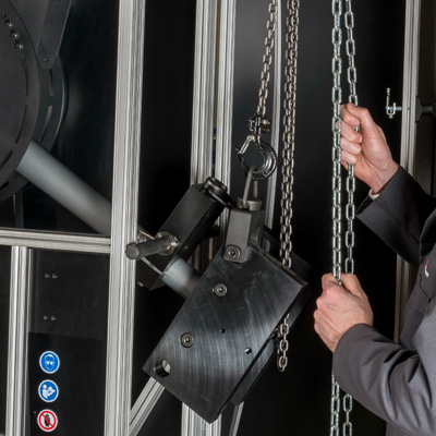
Catalog No. W-3577
Kit includes a chain hoist with a capacity of up to 500 kgf (1100 lbf) and a frame mounting bracket to suspend the hoist from an MPX Series pendulum impact machine. This kit is used to easily lift and securely support the hammer weights during weight changes, or the pendulum hammer assembly when replacing the striker, anvils, or other wear components.
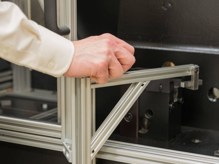
Catalog No. W-3598
The Charpy specimen loader device attaches to the MPX frame and uses a manually operated pivoting arm to place individual specimens on the anvil for ambient testing. The arm must be moved away for the door to close and the test to be performed. Kit includes the specimen loader assembly and mounting hardware.
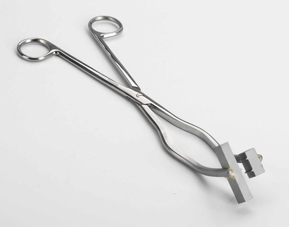
Tongs for handling and centering ambient and low-temperature Charpy and Izod specimens.
| Description | Catalog No. |
| Charpy Tongs | W-3550 |
| Izod Tongs | W-3587-D |

Charpy test kits include a Charpy impact striker, Charpy anvil inserts, and shrouds. These are for use on SI and MPX Series pendulum impact testing systems.
| Description | Catalog No. |
| Charpy Test Kit for ISO 148-2:2009 Includes: Charpy impact striker (2 mm Radius), and Charpy anvil inserts (1 mm radius), and shrouds |
W-3599-A |
| Charpy Test Kit for ASTM E23-12C (also complies with ISO 148-2:2009) Includes Charpy impact striker (8 mm radius), and Charpy anvil inserts (1 mm radius), and shrouds |
W-3599-B |

Catalog No. W-3587-C
Izod test conversion kit includes the components required to convert an MPX and SI Series pendulum impact tester to conduct an Izod test. Included are tongs for specimen handling, a magnetic specimen retrieval device and other necessary tooling. An Izod striker is not included.
Additional or spare Charpy impact strikers can be provided for testing with either a 2 or 8 mm radius.
| Description | Catalog No. |
| Charpy Impact Striker (2 mm radius) for ISO 148-2:2009 | W-3599-C |
| Charpy Impact Striker (8 mm radius) for ASTM E23-12C (also complies with ISO 148-2:2009) | W-3599-D |
Catalog No. W-3587-A
Izod impact striker for machine capacities 240 ft-lbf (325.4 joule) and greater.
Charpy specimen support sets are for use with SI and MPX Series pendulum impact testing systems and are compliant with ASTM E23-12C and ISO 148-1:2009.
| Description | Catalog No. |
| Standard (10 mm x 10 mm) Charpy Specimen Support Set | W-3585 |
| Subsize (7.5 mm x 10 mm Charpy Specimen Support Set (Set of 2) | W-3596 |
| Subsize (5.0 mm x 10 mm Charpy Specimen Support Set (Set of 2) | W-3595 |
| Subsize (2.5 mm x 10 mm Charpy Specimen Support Set | W-3594 |
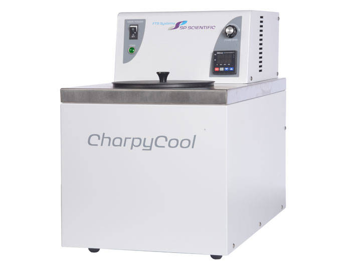
FTS Charpy Specimen Cooling Bath includes Charpy rack that holds up to 65 specimens and exceeds ASTM E23 / ISO 148 temperature stability requirements.
Note: Performance specifications are based on SP Scientific test data from units using methanol and operating at an ambient room temperature of approximately 22 C (72 F). Higher ambient temperatures and/or different fluids may interfere in the system's ability to achieve its ultimate low temperature.
| Description | Catalog No. |
| 220 V Cooling Bath (50 Hz, 6 AMP) | W-3609-A |
| 120 V Cooling Bath (60 Hz, 12 AMP) | W-3609-B |

Catalog No. W-3558
A centering gauge for positioning Charpy anvil and pendulum.

Catalog No. W-3561
A lateral expansion gauge for impact testing in accordance with ASTM A370.
用于非环境温度下的测试

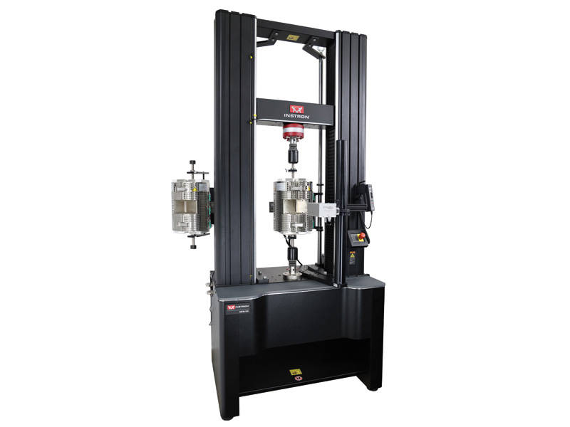
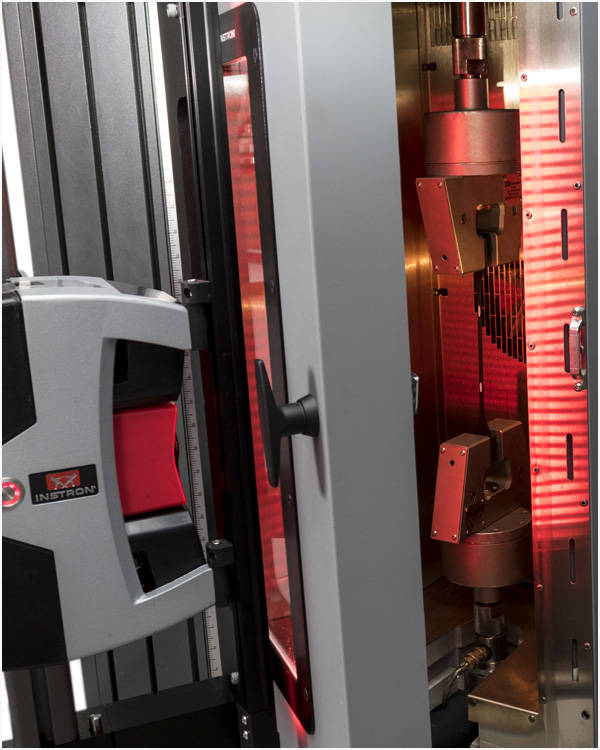
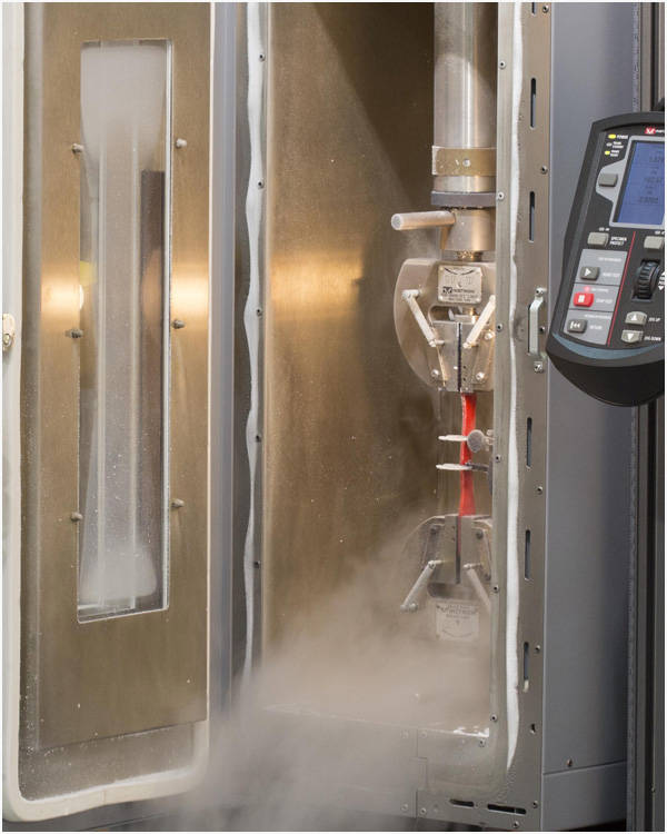
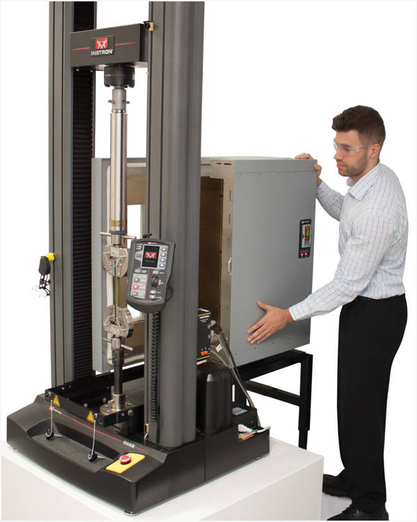
3119-600 系列环境箱兼容静态和动态试验系统,可提供广泛的温度测试能力,用于评估材料再非环境条件下的性能。 环境箱有多种标准尺寸可供选择,可固定在机架上或安装在滚轮支架上。 如果需要,它们也可以通过定制安装件安装到其他品牌的试验系统上。 此外,如果您的应用要求超出我们标准环境箱、夹具和工装的规格,Instron 可以为您定制完整的解决方案,包括加载链组件。
Instron 环境箱采用强制对流原理,热空气或冷空气在试样、夹具和拉杆周围循环,从而提供最佳的加热/冷却速率,减少温度梯度,并实现良好的热稳定性。 常温空气还可以从环境箱的后部进入隔热层和外侧板之间的空间。 这有助于环境箱的外壳保持凉爽。 风扇可选择高/低转速,减少空气流动的影响,让试样得到更精密的测试结果。

空气流经电热元件即可实现加热。 该系列的所有环境箱均标配加热功能。 您也可额外配置冷却阀,通过将低温气体(CO2 或者液氮)吹入环境箱即可实现冷却。 低温气体通常储存在钢瓶(液态 CO2 )或自增压杜瓦瓶(液氮)中。 低温废气通过专用端口排放至环境箱后部,并通过连接到该端口的硅橡胶管将废气排放到实验室外。


打开带有可加热光学玻璃窗的左手式铰链门,即可接触到试样和夹具。 如有需要,内部的灯光可以让您清楚地看到环境箱的内部。 门打开时,环境箱会自动关闭加热、冷却和风扇,从而减少热/冷空气对操作人员的影响。
环境箱中安装的专用 Eurotherm 3208 温度控制器用于选择所需的设定点温度。 温度由环境箱内的 N 型热电偶进行监测和控制。 控制器可以按照规定的加热速率和停留时间(8 段)进行编程,也可以使用兼容的 Instron 软件(通过 USB )与 PC 通信。 它还具有 0-10V 的温度模拟输出,可供图表记录器或其他设备使用。

3119-600 系列环境箱兼容全系列夹具、工装、引伸计和拉杆,可为大量非常温条件下的测试应用提供可靠、持久的性能支持。

| 目录编号 | 温度范围 需要冷却模块才能达到低于环境温度的水平。 | 内部尺寸 深 x 宽 x 高 | 外部尺寸 宽 x 高 |
|---|---|---|---|
| 3119-605 | -100 °C 至 350 °C | 230 x 240 x 485 mm | 350 x 635 mm |
| 3119-606 | -100 °C 至 350 °C | 230 x 240 x 560 mm | 350 x 710 mm |
| 3119-609 | -100 °C 至 350 °C | 230 x 240 x 660 mm | 350 x 810 mm |
| 3119-615 | -100 °C 至 350 °C | 230 x 240 x 860 mm | 350 x 1010 mm |

| 目录编号 | 温度范围 需要冷却模块才能达到低于环境温度的水平。 | 内部尺寸 深 x 宽 x 高 | 外部尺寸 宽 x 高 |
|---|---|---|---|
| 3119-607 | -150 °C 至 350 °C | 400 x 400 x 560 mm | 550 x 710 mm |
| 3119-608 | -150 °C 至 600 °C | 400 x 400 x 560 mm | 550 x 710 mm |
| 3119-610 | -150 °C 至 350 °C | 400 x 400 x 660 mm | 550 x 810 mm |
| 3119-616 | -80 °C 至 350 °C | 400 x 400 x 900 mm | 550 x 1050 mm |
| 3119-617 | -80 °C 至 350 °C | 400 x 400 x 760 mm | 550 x 910 mm |
| 3119-618 | -80 °C 至 350 °C | 400 x 400 x 1000 mm | 550 x 1050 mm |

对于需要超出标准环境箱所能提供的测试应用,我们的工程解决方案团队可根据您的需求为您量身定制专用的环境箱,包括更高或更宽的环境箱、具有更高温度额定值的环境箱以及定制化的加载链组件(如夹具和工装)。
Catalog no. 2715-001
Cord capstan grips are designed to permit faster, easier testing of twisted or braided cords. These grips are designed to permit predetermination of specimen length, and allow quick, convenient loading.
Principle of Operation
Cord capstan grips provide a superior method for clamping twisted or braided cord during testing. Each grip has a round capstan with a right-hand spiral grooved surface that accommodates specimens up to 3.2 mm (0.125 in) in diameter. The capstan is split axially into two halves, one half being stationary and the other movable. The specimen is wound from the outside of the capstan towards the center before being passed through the split halves where it is clamped. The groove completes 2.5 turns around the capstan, which allows two full turns for distributing the specimen load and stress concentration. The grips self tighten as load is applied to the specimen.
Smooth capstan surfaces are available separately.
Application Range

| Specifications | |
|---|---|
| Catalog no. | 2715-001 |
| Force Capacity | 2.5 kN |
| Maximum Specimen Diameter | 3.2 mm |
| Temperature Range | -73 °C to 316 °C |
| View Full Specifications | Download Brochure |
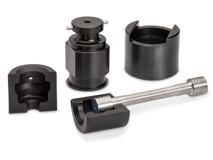
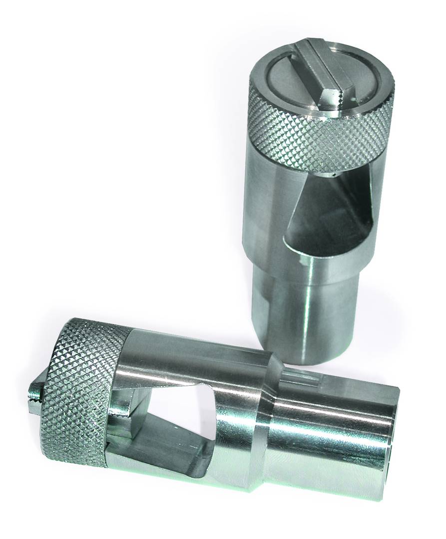
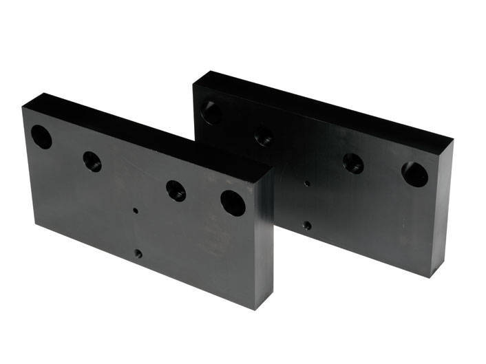
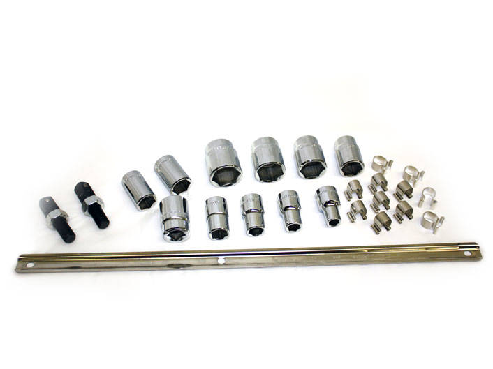
Split insert tensile grips are designed for safe, high-volume production testing of threaded-end, shoulder-end, or button-end machined specimens. Engineered with an operator focus, the split insert style tensile grips are easy to install, offer quick change inserts for standard specimen sizes, and promote efficient static testing of a wide range of metals and alloys. A preferred solution for the testing of high-strength, high-toughness materials that may damage or cause excessive wear to traditional grip arrangements. These grips are designed to comply with ASTM E8, ASTM A370, or ASTM A48, and other international standards, and can be made to custom specifications. A wide range of possible button-end, shank hole, and chamfer / radius dimension options ensures compatibility with a large variety of specimen sizes.
Debris shields, also known as protective shields, provide a protective barrier between the test space and the operator. These may be necessary for materials that exhibit violent failures under test, such as composites, rebar, and cables.

These debris shields feature an anodized extruded aluminum frame and clear Lexan® panels that offer unobstructed views of the text space. A hinged-style access door is available with or without door safety interlocks.
| Compatible Frames | Catalog Number |
| Single Columns | 500 N Systems: 334X, 34SC, 594X, 68SC |
CP127700 |
| Single Columns | 1 - 5 kN Systems | Standard Height: 334X, 34SC, 594X, 68SC |
CP127701 |
| Single Columns | 5 kN Systems| Extra Height: 3345, 34SC-5, 68SC-5 |
CP127702 |
| Table Models | Standard Width: 336X (dual T-slot column cover style only), 34TM, 446X, 556X, 586X, 596X, 68TM |
2910-074 |
| Floor Models: 3382, 3384, 3385H, 34FM, 4481, 4482, 4484, 4485, 5581, 5582, 5584, 5585, 5585H, 5881, 5882, 5884, 5885, 5885H, 5982, 5984, 5985, 5985, 68FM |
2910-062 |
Depending on user-preference and footprint limitations, a sliding debris shield is available for table model universal testing systems. The sheet metal and polycarbonate shield encase the front of the test machine, separating the user from debris and moving parts while also giving excellent visibility. To access the test space, the sliding door is opened to the left and specimens and grips can be loaded through the 845mm tall and 440mm wide port. The debris shield can be equipped with an optional magnetic interlock which prevents tests from being started with the door open and can be configured to prevent all crosshead motion when the door is open.
| Compatible Frames | Catalog Number |
| 68TM, 34TM, 336X, 596X | Standard Height, Standard Width | CP129040 |
| 68TM | Extra Height, Standard Width | CP129044 |
| 34TM, 336X, 596X | Extra Height, Standard Width | CP126003 |
| 336X, 596X | Standard Height, Standard Width | CP126002 |
用于测试成品和部件

部件测试平台是一种钻孔攻丝金属板,可直接安装在单立柱和双立柱试验系统机架的底座上。其表面布满了一系列可用于多种用途的 M6 螺纹孔,可将组件或成品安装到板上进行拉伸、压缩、弯曲、剥离或穿刺试验。您可以借助该测试板偏心安装夹具,便于将定制的工装夹具适配到您的试验系统中。
工作原理
部件或成品可直接使用兼容的 M6 螺纹孔或机械老虎钳固定在部件测试平台上。应选定试样在板上的位置,以便目标区域(即负载处)完全居中。若加载链偏离中心,可能会损坏载荷传感器。
部件测试平台还兼容 Instron 标准底座适配器(O 型和 D 型),可通过平台上的任意 M6 螺纹孔将其安装到测试平台上 - 这便于您将夹具偏心安装,或将定制的工装夹具适配到试验系统上。
应用范围
| 规格 | ||||
|---|---|---|---|---|
| 目录编号 | 适配的试验系统 | 载荷 | 宽度 | 深度 |
| 2910-108 | 单立柱试验系统 68SC |
1 kN | 600 mm | 300 mm |
| 2910-107 | 双立柱试验系统 68TM、34TM、596x、336x、556x、556xA、446x |
2 kN | 300 mm | 300 mm |
| 2910-106 | 单立柱试验系统 334x |
1 kN | 600 mm | 300 mm |
| 2910-105 | 单立柱试验系统 34SC、594x、554x |
1 kN | 600 mm | 300 mm |
| CP129729 | 超宽双立柱试验系统 68TM-30 |
30 kM | 914 mm | 610 mm |
| CP129738 | 双立柱试验系统 68TM、34TM、596x、336x、556x、556xA、446x |
30 kN | 400 mm | 400 mm |
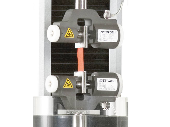
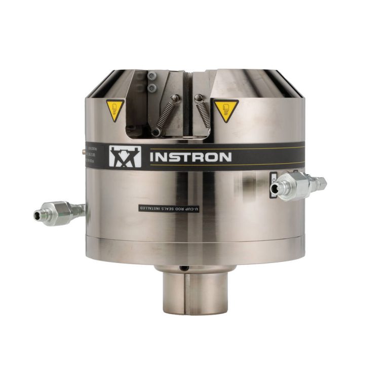
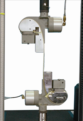
Instron 气动楔形夹具可用于静态或动态材料测试,楔形夹面可灵活互换,无论是平板试样还是圆棒试样,均可适配。
该夹具设计旨在能牢固夹持测试试样,同时不会对试样产生轴向预加载。这是通过采用仅沿水平方向相对于试样移动的夹面得以实现
每个夹具都能独立于另一个夹具工作,外部液压源为夹具的开合供应压力。
当施加夹持压力时,试样与夹面的相对垂直位置保持不变,以避免夹持过程中试样产生负载。
一旦夹面接触到试样后,液压就会在夹面上产生垂直力。由于该设计可自动补偿试样厚度变化,夹具夹持力能保持恒定。
单位
| 产品名称 | 目录 # |
|---|---|
| 2742-103 ±1 kN 气动疲劳夹具 |
2742-103 |
| 2742-205 ±3 kN, ±25 Nm 气动疲劳夹具 |
2742-205 |
| 2742-315 ±10 kN ±100 Nm 气动疲劳夹具 |
2742-315 |
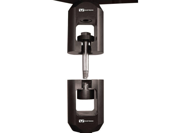
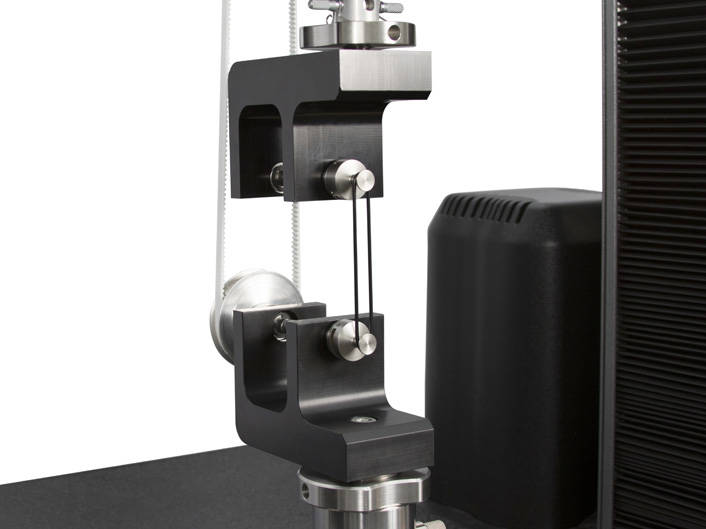
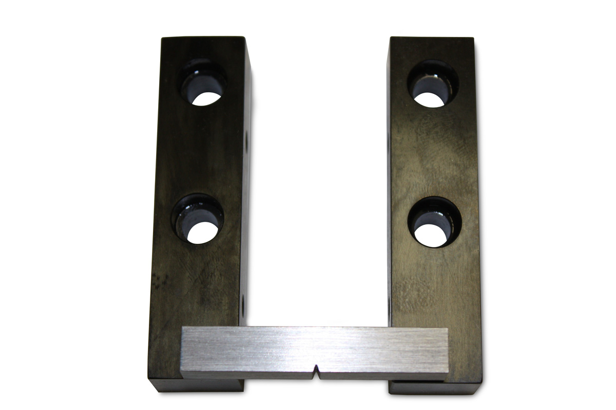
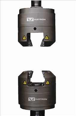
Clevis Grips for Fracture Mechanics
Units
| Item Name | Capacity | Specimen Width | Cat# |
|---|---|---|---|
| Compact Tension Fixtures for 50mm wide Compact Tension Specimens | ±250 dynamic, 500 static kN | 50 mm | 2750-120 |
| High Temperature Clevis Grips | 0.8 @ 1000 deg.C kN | 12.5 mm | 2420C |
| Compact Tension Fixtures for 12.5mm Thick Compact Tension Specimens | ±10 dynamic, 20 static kN | 12.5 mm | 2780-118 |
| Compact Tension Fixtures for 25mm Thick Compact Tension Specimens | ±50 dynamic, 100 static kN | 25 mm | 2780-119 |
| Additional Extension Rod | 2780 120 |
气动楔形夹具的前端开口设计,便于大型试样的轻松装载。该系列可容纳直径最大达 60mm(2.36 in)的圆棒形试样以及厚度最大达 70mm(2.75 in)的平板试样。在安装到 Instron 的落地式试验系统时,这些气动楔形夹具的紧凑型设计可实现试验区域的最大化利用。
这些夹具特别适用于可能存在灰尘和金属碎屑的工业环境,其配备的防尘保护罩可轻松套在夹面外,保护活动表面。可选配的背驮式转接板提供了一种高效方式,无需拆卸大型夹具即可安装次级载荷链,用于小量程试验。
在 2716-110 和 2716-120 型夹具上,用于圆形试样的楔形面在设计上减少了中心区域的面积,这使其在承受高能量断裂时容易受损。而该款夹具采用分体式 V 型夹面设计,能够分散断裂能量,避免夹面受损。对于 W-5180 和 W-5190 型夹具,由于其尺寸显著增大,因此可以采用一体式夹持面设计。
这些夹具通过安装在夹具上的控制旋钮或 Instron 标准气动控制套件进行操作。夹持面由气动控制驱动,通过气动活塞移动,从而省去了昂贵的液压泵及其控制装置。在受力时,楔形作用会提供额外的夹持力,以最大程度减少试样打滑。
2716-110 和 2716-120 型夹具采用独特的托架 / 夹面安装系统,便于快速更换夹面。托架安装在夹具上,通过夹具本体的弹簧固定,并与驱动活塞相抵;夹面则放置在托架上,由几个翼形螺钉固定。夹面托架的润滑通过标准注油嘴进行,无需拆卸夹面或托架即可完成注油。每套夹面可适配多种试样类型,只需更换极少次数的夹面就能满足不同需求,灵活性很强。
W - 5180 和 W - 5190 夹具的夹面安装系统带有嵌入式磁铁和带有圆形定心盘的夹面。这种设计简化了夹面的装载过程,并且在无载荷施加时能使夹面保持在相应位置。
单位
| 测试项目名称 | 载荷 | 上部配件 | 目录编号 |
|---|---|---|---|
| 气动楔形夹具;载荷:100 kN |
100 kN 22,500 lbf |
0.5 in 销钉(Dm 型) |
2716-111 |
| 气动楔形夹具;载荷:200 kN |
200 kN 45,000 lbf |
M48x2mLH(IImLH 型) |
2716-121 |
W-E404 系列横向引伸计专为测量横向位移而设计。该设备可自行固定于试样表面,适用于任意宽度或直径在 0 至 25 mm(1 in)范围内的试样。
W-E404-A/C/E/F 型(引伸计)通常用于测量复合材料等各种异性材料的泊松比和横向应变。它们常与轴向引伸计配合使用。这些装置可轻松夹持在试样上,并通过内置弹簧固定。其圆形接触边缘有助于保持在试样上的位置。
专用的平均值版本 (2640-010) 可用于确定金属板材的 “r” 值(不适用于泊松比)。
试样位移通过一个高精度双挠曲应变片传感器在单点进行测量,该传感器专为提升强度和性能而设计。
用于 “r 值” 测量的专用版本通过两个独立的高精度双挠曲应变片传感器,在两个点对试样位移进行测量。每个传感器的输出会被合并,以生成一个单一的平均输出。
该设计使这些装置具有极高的耐用性,即使在试样发生断裂的情况下,也可保持安装在试样上。
引伸计安装简便,并配备内置弹簧,可将设备固定在试样上。刀口下方可调节的试样接触杆为引伸计主体提供了良好的稳定性。
单位
| 测试项目名称 | 横向行程 | 目录编号# |
|---|---|---|
| 横向平均引伸计 | 2640-010 | |
| 横向引伸计,范围 +/- 2.5 mm | W-E404-F | |
| 横向引伸计,范围 +/- 0.1 in | W-E404-C | |
| 横向引伸计,范围 +/- 0.5 mm | W-E404-E |
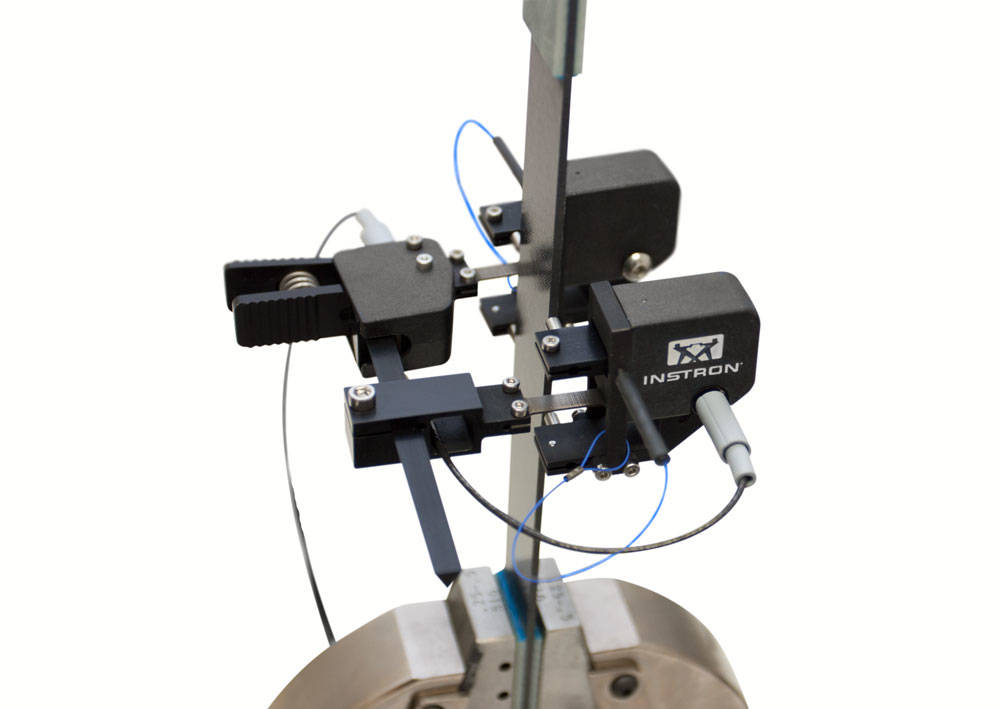
这些平均轴向夹式拉伸计可测量试样两侧的轴向应变。可提供单个平均应变输出或两个独立的轴向应变输出。在任何情况下,使用平均轴向应变都可纠正因错位造成的试样弯曲,从而一致地确定模量等材料属性。独立输出版本可同时监测平均轴向应变和弯曲应变。
拉伸计使用应变片进行测量,由高强度铝、钛和不锈钢制成。所有拉伸计都具有简单、单手操作的特点,可确保结果的一致性,并便于在温室内安全使用。拉伸计具有自动电气校准和传感器识别功能,包括唯一的数字序列号。
伸长计标配锥形触点,建议用于大多数复合材料。还有其他触点可供选择:线状触点,建议用于热塑性塑料等软质材料;矢状触点,最适合用于薄截面测试样本。
单位
| 项目名称 | 旅行轴 | 型号 |
|---|---|---|
| 平均拉伸计,25 毫米量规长度,+5 / -2% 应变,单输出 | -2 至 +5 | 2650-560 |
| 平均拉伸计,1 英寸量规长度,+5 / -2% 应变,单输出 | -2 至 +5 | 2650-564 |
Instron 2650 系列双轴引伸计非常适合测试各种材料,包括聚合物基复合材料、金属和塑料,且可在不同温度范围内进行测试。两个传感器分别测量试样两侧的轴向应变,第三个传感器测量横向应变。这些引伸计符合 ASTM E83 类 B1、ISO 9513 类 0.5 以及 ISO 527 的校准要求。
这些双轴夹持式引伸计使用应变片进行测量,并由高强度铝、钛和不锈钢制成。所有引伸计均具有简单的单手操作功能,这不仅能确保测试结果的一致性,还有助于在环境箱内安全使用。此外,该引伸计集成了自动电气校准和传感器识别功能,包括一个独特的数字序列号。
所有引伸计均可测量试样两侧的轴向应变,部分版本可提供单一平均轴向应变输出或两个独立的轴向应变输出。在所有情况下,采用平均轴向应变都能校正因对准偏差导致的试样弯曲,从而保证弹性模量测定结果的一致性与准确性。独立输出版本能够同时监测平均轴向应变和弯曲应变。此外,该引伸计还配有测量横向应变的传感器,可用于测定泊松比、面内剪切模量等材料性能参数。
锥形接触点作为标准配置随引伸计提供,并推荐用于大多数复合材料。还提供其他接触选项:线接触点,推荐用于热塑性塑料等软材料;以及 V 型接触点,最适合用于薄壁试样。
单位
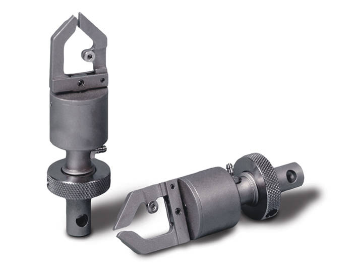
气动式和制动式拉伸夹具用于测试绳索、轮胎帘线、钢丝、电缆、纱线和纤维束试样。
Instron® Crack Opening Displacement transducers are designed
specifically to perform standard ASTM and ISO fracture mechanics
tests (both cyclic and static), covering all common specimen
geometries (CT, SEB, Centre Crack, Arc Shaped).
Each model offers class leading linearity, whilst being rugged
enough to withstand the high energy release common in many
of these applications and can be used at both elevated and sub
ambient temperatures.
These gauges comply with requirements laid down in ASTM E399-09.
These machines are developed to obtain specimens by punching, using hollow dies of different sizes and contours. Several hundreds of dies can be created by interchangeable socket punches with different profiles and size according to the standards and to the customer needs. Dies are made of steel with hand finished cutting edges and can be provided with ejector for easy removal of the specimen after punching.
Compact design of instrument for an easy and fast preparation
Manual and automatic models obtain specimens of different size and geometries for a wide range of plastics testing applications
High level of results repeatability and time saving test procedures

The Custom Solutions group at Instron has been developing unique grips and platens to meet our customers’ unique needs for decades. Customized cord and yarn grips or custom webbing grips of various sizes are just a small example of things that we can do. Whether your grip or platen is being purchased with a new frame or being used with your current set-up, we will work diligently to understand your goals and ensure they are met or exceeded. Please browse the gallery above to see some of our recent projects.
We also make specialized jaw faces!
Click here to see our existing customized grips or platens for specific applications.
Requires: grip faces and fatigue rated adapters
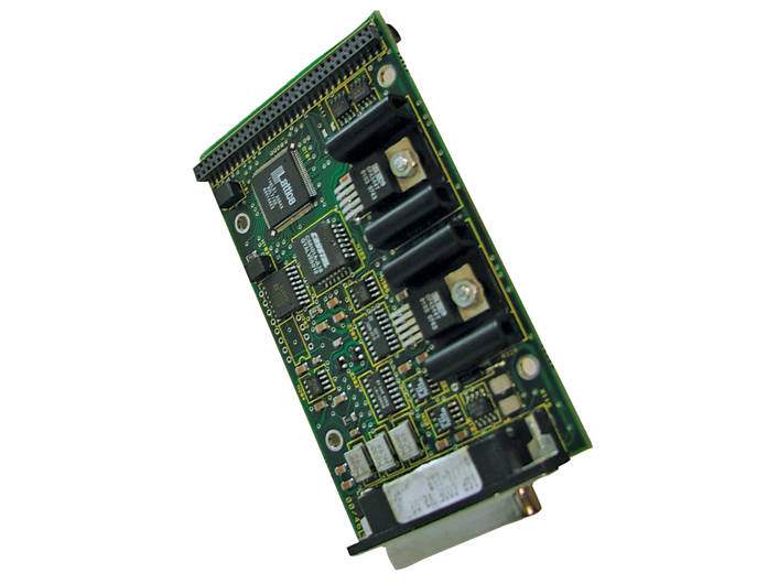
Quantity: 2 grips

Capacity: 500 N (100 lb, 50 kgf).
| Notes | For holding PCBs and assemblies |
Capacity: 2.2 kN (500 lb, 220 kg)
Minimum specimen diameter: 0.125 mm (0.005 in).
Maximum specimen diameter: 1.52 mm (0.06 in).
Upper and lower fittings: Type Om (12 mm connection with 6 mm diameter clevis pin).
| Accessory Height | 101 mm (4 in) |
| Accessory Width | 84 mm (3.3125 in) |
| Capacity | 2.22 kN (500 lbf) |
| Effective Length | 139 mm (5.472 in) |
| Lower Fitting | 6 mm clevis pin (Type Om) |
| Specimen Diameter | 0.125 - 1.5 mm (0.005 - 0.06 in) |
| Temperature Rating | +10 to +40 °C (+50 to +150 °F) |
| Upper Fitting | 6 mm clevis pin (Type Om) |


The Custom Solutions group at Instron has been developing unique fixtures to meet our customers’ unique needs for decades. If you need to push or pull against something unique or novel, like yak hair or pizza dough, we are interested in learning more about it. Whether your fixture is being purchased with a new frame or being used with your current set-up, we will work diligently to understand your goals and ensure they are met or exceeded. Please browse the gallery above to see some of our recent projects.
Click here to see our existing customized fixtures for specific applications.
Transverse Averaging Extensometer with single channel output for attachment to thin rigid specimens, 0.3 mm to 4 mm thick.
Accepts specimens from 10 mm to 20 mm wide and from 15 mm to 25 mm wide. Suitable for ´r´ and ´n´ testing on sheet metals.
Requires suitable axial extensometer of 50 mm gauge length minimum for ´r´ value determination. Requires single strain conditioner.
Temperature Range: -80 °C to +100 °C
The 2640 series averaging transverse extensometer is designed to measure average transverse gauge length and strain with a single output channel.

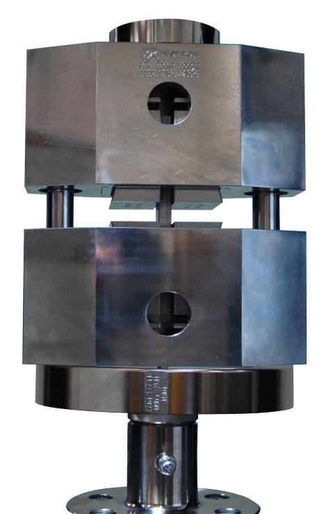
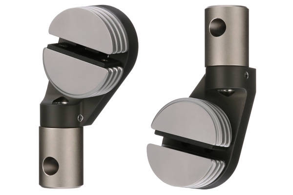
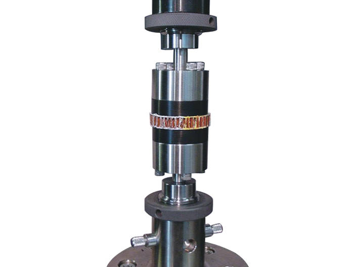
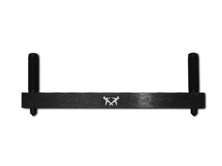
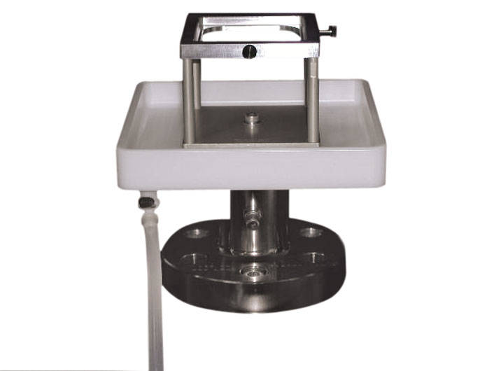
Compression parallel to grain per ASTM D143 (primary method).
Requires Platens (75 mm (3 in) minimum diameter for primary method, Spherical Seat and Extensometer (2630); order separately.
| Accessory Weight | 0.65 kg (1.4 lb) |
| Specimen Zone | 200 mm (8 in) |
| Specimen Thickness | 50 mm (2 in) |
| Specimen Width | 50 mm (2 in) |
| Testing Standards | BS 373, ASTM D 143 |
| Upper Effective Length | 150 mm (6 in) |
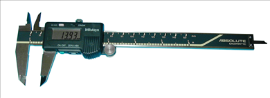

Digital caliper with carbide standard jaws. Resolution of 0.0005" (0.01mm). Accuracy of ±0.001" (±0.02mm). Repeatability of 0.0005" (0.01mm).
Designed to be used in conjunction with Automatic Data Entry Interface listed separately. Qualifies as one (1) device. Includes case.
Note: This measuring device requires an Automatic Data Entry Interface listed separately for direct entry of measurements into software.

Biaxial Extensometer 2 inch Gauge Length providing one averaged axial and one transverse strain measurement.
Features:
Transverse Travel +/- 0.02 in (Strain range depends on specimen width)
The extensometer provides a single averaged axial output along with a single transverse output and requires 2 Sensor channels. It has electrical calibration and is self-identifying with 3300, 3400, 4200, 4300, 4400, 4500, 5500, 5800, 5900, 6800, 8500, 8800 Tower, and 8800MT Series Systems.
The extensometer is supplied with a single set of conical point specimen contacts.
These bi-axial and averaging axial clip-on extensometers use strain gauges for measurement and are constructed from high-strength aluminum, titanium, and stainless steel. All of the extensometers feature simple, single-handed operation. The extensometer incorporates automatic electrical calibration and transducer recognition including a unique digital serial number.


Instead of working with a pallet mounted onto the crash sled, the patented Instron two piece sled integrates the pallet system into the sled design. This allows for much faster set up times using multiple pallets whilst significantly reducing the overall mass of the sled to provide a higher dynamic performance.
The pallets can be tailored to meet the specific needs of the test laboratory.
Back to CSA.
0.5" gauge length.
| Gauge Length | 0.50 in |
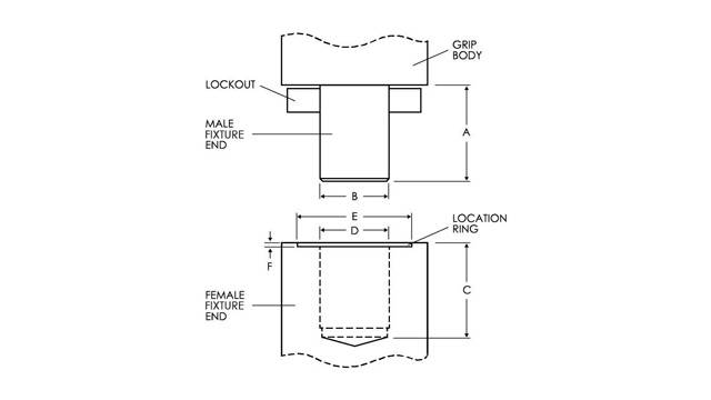
Capacity 300 kN (67,500 lbf, 30,000 kgf)
Specimen Range:
Minimum Specimen Length without the use of an extensometer is 270 mm (10.63 in)
Ambient temperature use only.
Upper and Lower Fittings: Type IIfRH (M48 x 2)
Weight Per Grip Body 123 kg (270 lb)
Grip Body Dimensions W x L x D: 445 x 302 x 127 mm (17.5 x 11.875 x 5 in)
Effective Length using standard threaded mounting:
Grip faces sold separately use: W-5246 & W-5247 series grip faces
Configuration Notes:
| Accessory Weight | 123 kg (270 lb) |
| Accessory Width | 445 mm (17.5 in) |
| Capacity | 300 kN (67,500 lbf) |
| Lower Fitting | Type IIfRH (M48x2) |
| Temperature Rating | 10-38 °C (50-100 °F) |
| Upper Effective Length | 329 mm (13.0 in) |
| Upper Fitting | Type IIfRH (M48x2) |
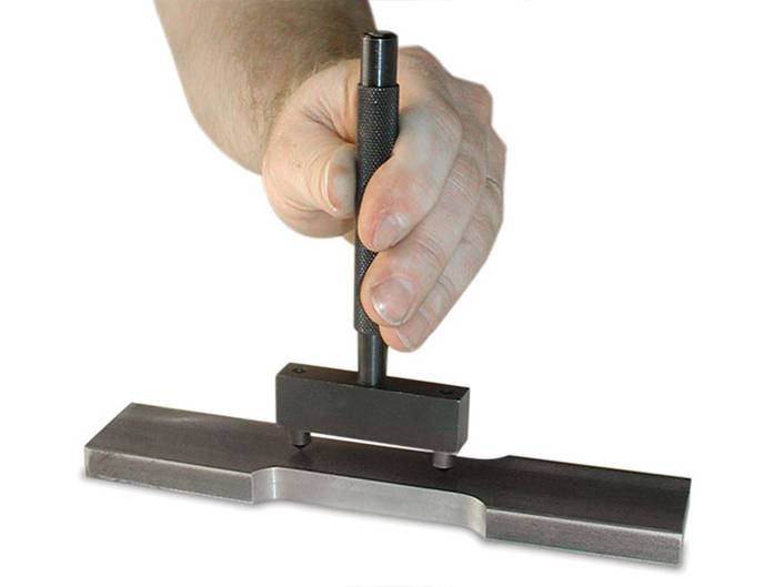
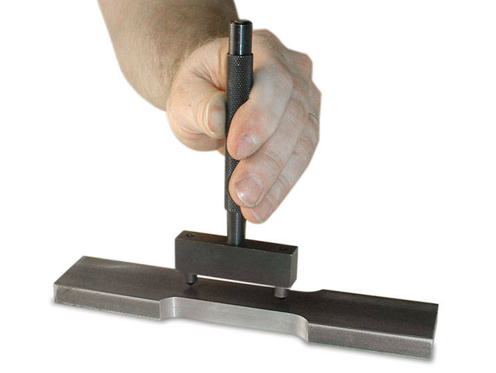
For Instron standard manual gauge punch devices.
Suitable for 1 inch, 2 inch, 1.4 inch, 25 mm or 50 mm gauge lengths.

Biaxial Extensometer 1 inch Gauge Length providing one averaged axial and one transverse strain measurement.
Features:
Transverse Travel +/- 0.02 in (Strain range depends on specimen width)
The extensometer provides a single averaged axial output along with a single transverse output and requires 2 Sensor channels. It has electrical calibration and is self-identifying with 3300, 3400, 4200, 4300, 4400, 4500, 5500, 5800, 5900, 6800, 8500, 8800 Tower, and 8800MT Series Systems.
The extensometer is supplied with a single set of conical point specimen contacts.
These bi-axial and averaging axial clip-on extensometers use strain gauges for measurement and are constructed from high-strength aluminum, titanium, and stainless steel. All of the extensometers feature simple, single-handed operation. The extensometer incorporates automatic electrical calibration and transducer recognition including a unique digital serial number.

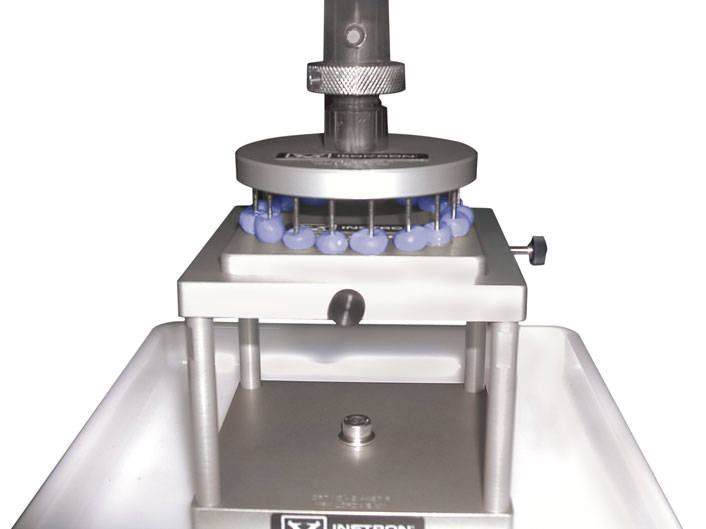
Set includes 9 probes
Upper fitting: Requires Chuck 2830-036.
Lower fitting: Requires optional support plates with Drip tray S5400A and Support Frame S4427A.
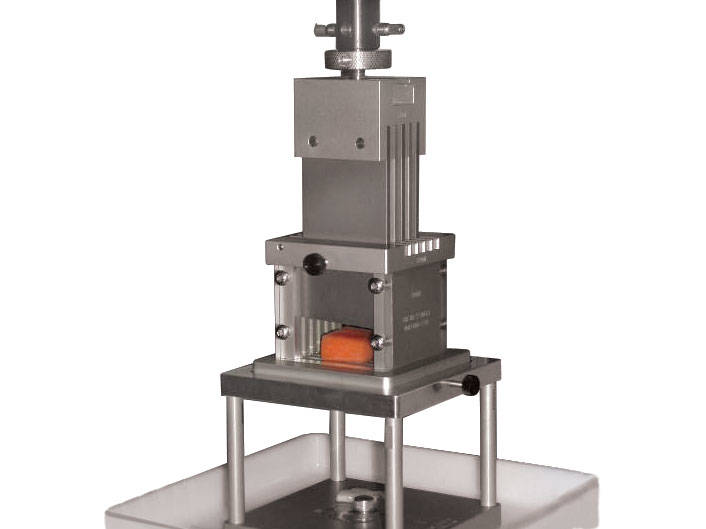
Flat-end puncture probes produce a shear stress in the specimen. The force required to cause shearing as the probe penetrates the specimen relates to texture properties such as firmness and hardness.
Capacity: 2 kN
Dimensions: 1 mm (0.039 in) thick x 50 mm(2 in) wide blade. Similar to Warner Bratzler blade without the V-notch.
Upper fitting: 6 mm clevis, male
Lower fitting: Requires Warner Bratzler S5406A
*May use with S5401A plain plate for Noodle Shearing test
500 kN (110 kip) Dynamic Capacity, With 100mm (3.94 in) Diameter Upper Roller and 50mm (1.97 in) Diameter Lower Rollers
Requires: fatigue rated adapters
Catalog number 2810-250
Rated capacity 500 kN (50000 kgf, 112500 lbf)
3-point flexure fixture with an optional conversion kit for 4-point loading
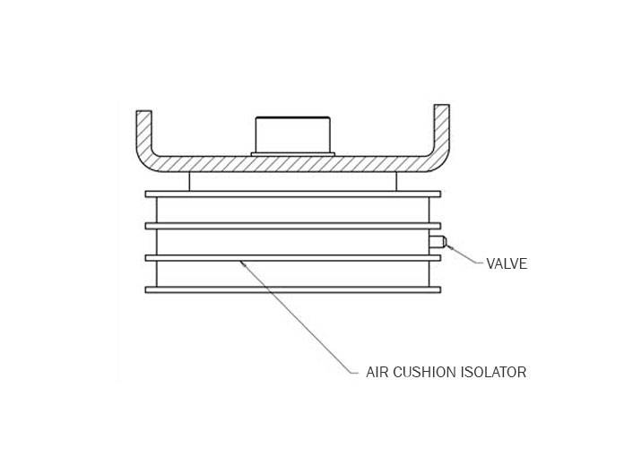
Air Cushion Isolators (for frames 3 & 4). Not suitable for 8801 or 8516 (1 Set)
Suitable for testing frequencies above 15Hz.
| Compatible Frame Models | Air Cushion Isolators (for frames 3 & 4). Not suitable for 8801 or 8516 Suitable for testing frequ |
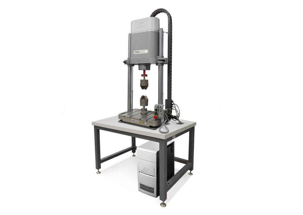
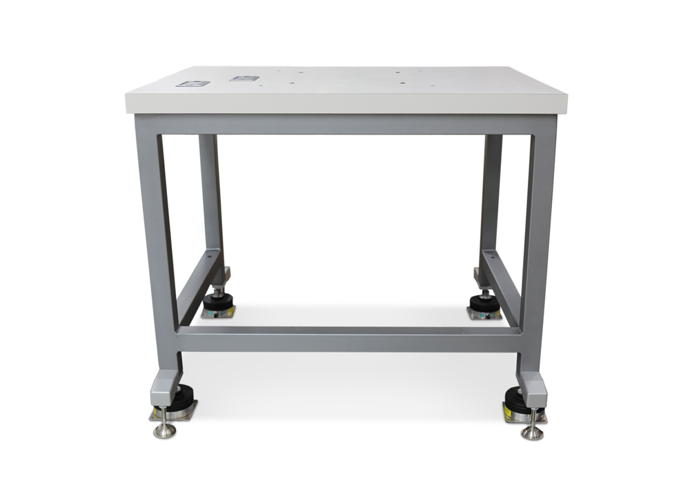
For mounting ElectroPuls table-top systems when used for low to medium acceleration dynamic tests (accelerations below 6g)
Robust design with high stiffness grey frame and light-grey scratch-resistant table-top
Pre-drilled with mounting holes to suit E1000 or E3000 systems
| Model | Height | Width | Depth | Weight | ||||
|---|---|---|---|---|---|---|---|---|
| mm | in | mm | in | mm | in | kg | lb | |
| 1300-311 | 785 | 31 | 1000 | 39 | 750 | 30 | 56 | 123 |
| 1300-315 | 800 | 32 | 1000 | 39 | 750 | 30 | 65 | 143 |
High-Stiffness Support Table for ElectroPuls E1000 and E3000 tabletop test instruments.
Combination 25mm and 50 mm Manual Gauge Point Punch.
| Gauge Length | 25/50 mm |

Dynamic Extensometer for direct strain measurement and closed loop strain control. Suitable for tensile, compressive & fatigue testing, the extensometer has a 12.5mm gauge length with a travel of ±5mm giving ±40% strain.
It includes a 12.5mm extender to give a gauge length of 25mm and ±20% strain and a 37.5mm extender to give a gauge length of 50mm and strain of ±10%.
Temperature range: -80C to +200C. Compatible with 8800 and 8500Plus controllers. May be immersed in acetone, silicone or alcohol.
Wide operating temperature range, from -80 °C to 200 °C (-112 °F to 392 °F)
Designed to meet the requirements of ISO 9513, BS 3846 and ASTM E 83
This guide provides instructions on how to use your system components and controls, procedures for setting limits, calibration and other frequently performed operating tasks.
Fracture Mechanics Fixtures for 50 mm wide compact tension specimen.
Rated capacity: ±250kN Dynamic, 500 kN Static
Requires: fatigue rated adapters. Mechanical interface M48 x 2 right hand female thread.
(1 Pair)
Supports closed-loop control and data acquisition for only one transducer (strain gage bridge, LVDT, or +/-10V BNC input).
Includes:
Note: Not recommended for customer installation to an existing tower. Always include service time when quoting as an accessory
Per MIL-STD-3010
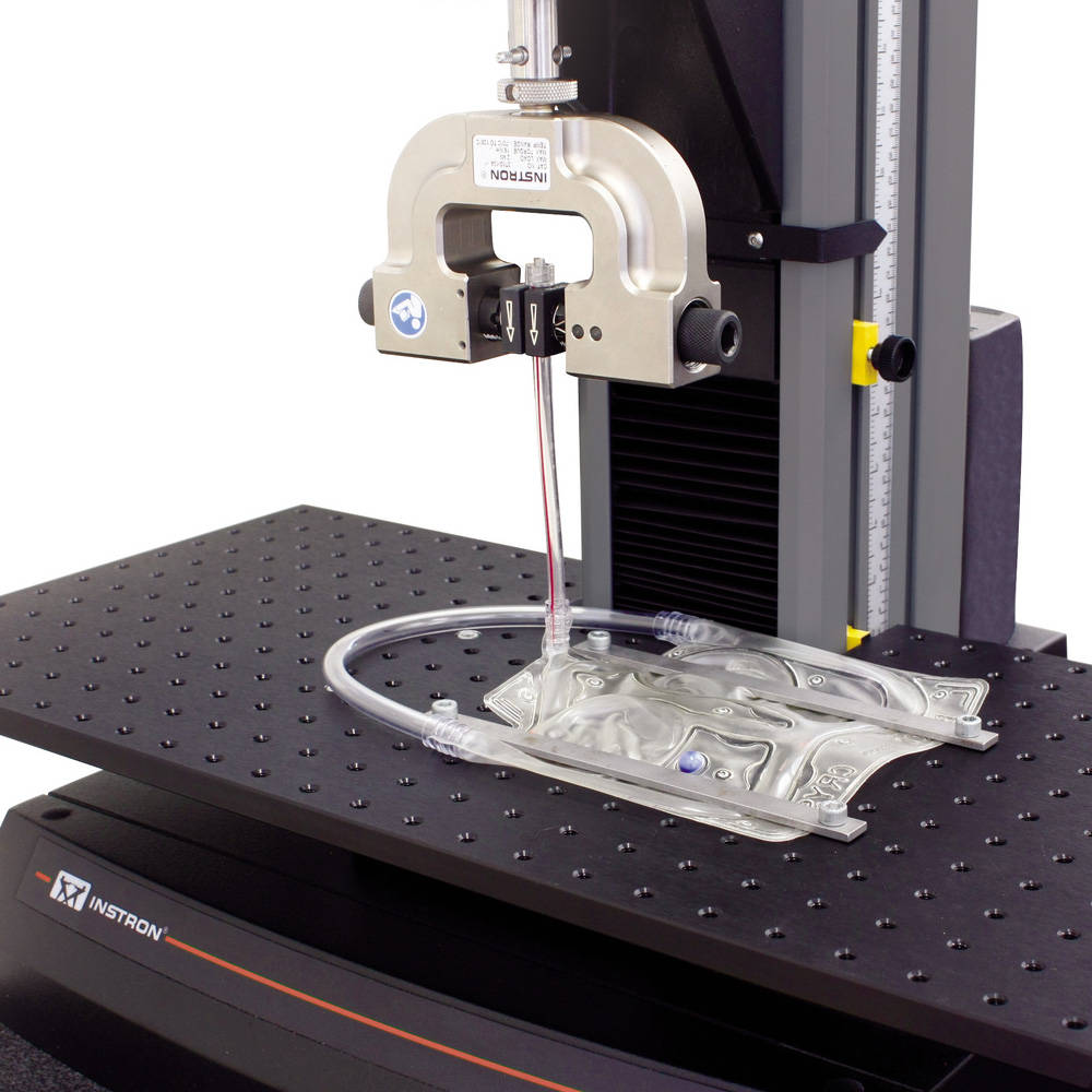
Simple puncture fixture with clearly specified dimensions.
Upper fitting: Type O (12 mm connection with 6 mm clevis pin)
Lower fitting: Type D (1.25 in connection with 1/2 in clevis pin)
| 附件身高 | 356 mm (14 in) |
| Accessory Width | 125 mm (5 in) |
| 容量 | 2.5 kN (500 lbf) |
| Lower Fitting | 1/2 inch Clevis Pin (Type Dm) |
| Temperature Rating | +10 to +40 °C (+50 to +100 °F) |
| Testing Standards | MIL-STD-3010 |
| Upper Fitting | 6 mm Clevis Pin (Type Om) |
Digital micrometer with flat anvils for measuring outside diameter and thickness. Resolution of 0.00005" (0.001mm). Accuracy of ±0.0001" (±0.002mm).
Designed to be used in conjunction with Automatic Data Entry Interface listed separately. Qualifies as one (1) device. Includes case.
Note: This measuring device requires an Automatic Data Entry Interface listed separately for direct entry of measurements into software.
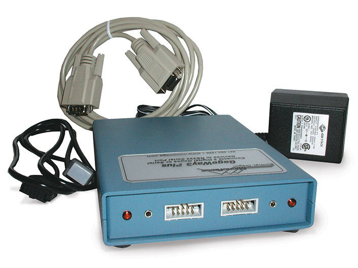
Partner Interface that translates and routes data from a device with an RS-232 output into the Partner software (i.e. micrometer, caliper, barcode reader, etc).
Allows the use of up to two (2) such devices. Requires one (1) PC serial port.
Includes all necessary hardware and software.
Notes:
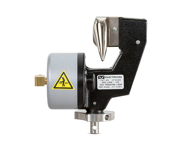
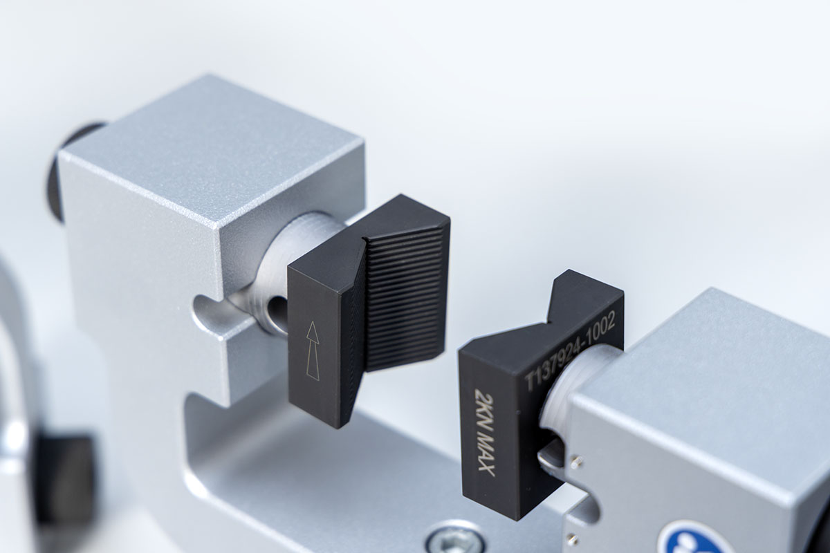
Capacity: 5.0 kN (1,000 lb, 500 kg).
Incorporates a surfalloy coated clamping surface.
Temperature range: -10 °C to 80 °C (14 °F to 176 °F).
Maximum specimen diameter: 2 mm (0.08 in).
Upper and lower fittings: Type Dm (1.25 in connection with ½ in clevis pin).
Requires a rigid coupling and an Automatic Air Control Kit or Pneumatic Foot Switch
The Instron® pneumatic tire cord grips provide a convenient method for clamping tire cord and braided wire during testing. A guide pin allows for easy loading onto a graduated radius cam, which provides a stress-reduced clamping area on the specimen. The clamping mechanism can be activated either automatically or through a footswitch, which allows for hands-free grip operation enabling the specimen to be held with both hands for easy loading. Pneumatic cord and yarn grips provide selectable clamping force to accommodate different materials and excellent follow-up action that compensates for decay of the holding force due to specimen creep.
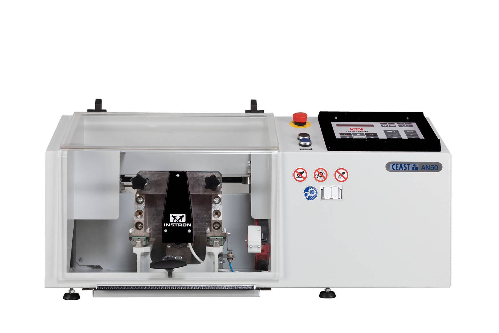

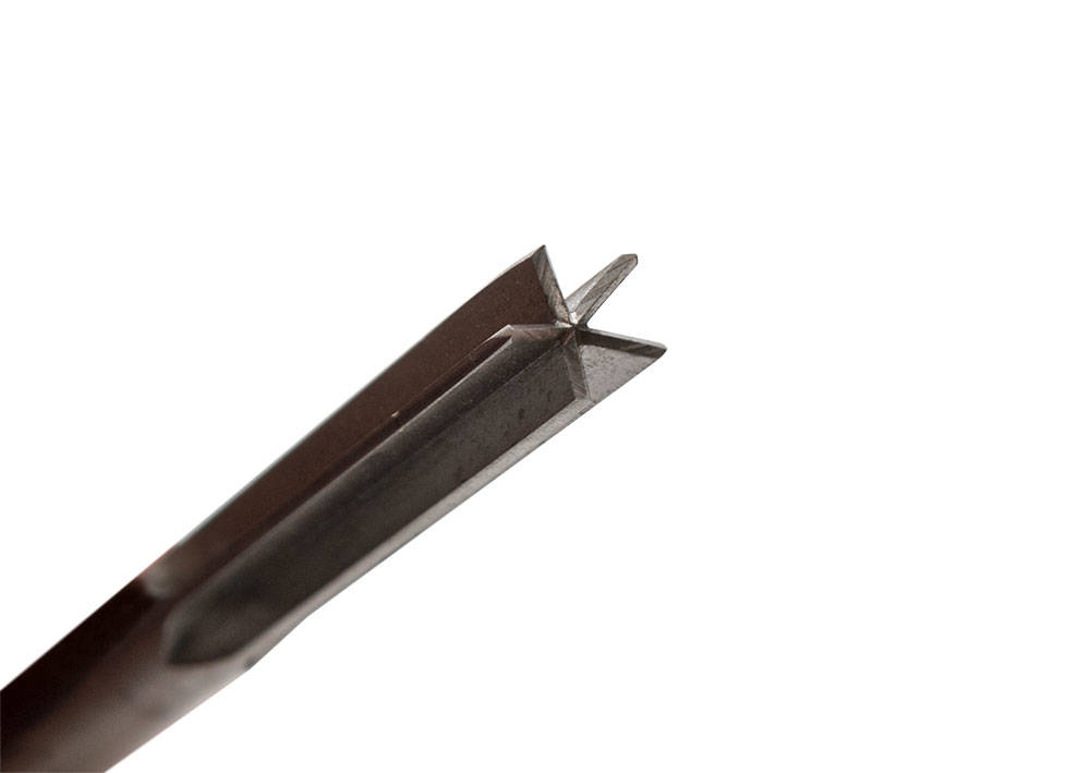
Notching machines are designed to notch specimens for impact resilience according to Izod, Charpy and Tensile impact methods. These instruments use a linear knife cutting technique to avoid overheating and consequent stresses during the specimen's notching operations. Therefore, an accurate notch preparation is guaranteed. Manual, motorized and fully-automatic models are available to cover the different testing needs.
Rated Capacity: ±50kN Dynamic, 100kN Static
Temperature Range: -50 to 315°C
Overall accessory length 400mm
Includes:
Capacity 2000kN
(450,000 lbf, 200,000 kgf)
Specimen ranges:
Grips are supplied with:
Grips interfaced to the machine’s hydraulic power supply when ordered with a new hydraulic UTM. (Consult factory for interfacing of grips to an existing machine or for systems where an independent hydraulic power supply is required)
Efective grip heights:
Upper grip: 715 mm (28.125 in.)
Lower Grip: 770 mm (30.3125 in.)
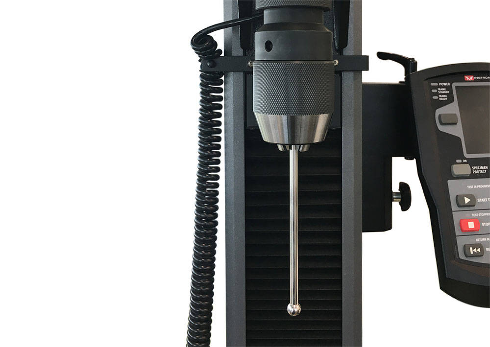
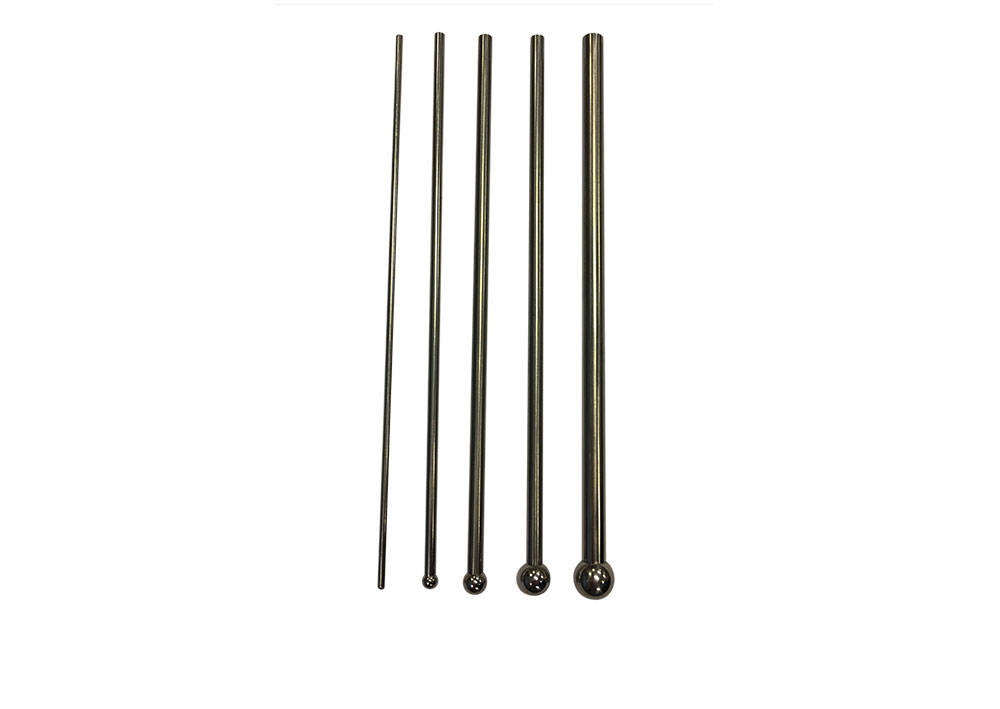
Capacity: 1 kN
Dimensions: 2 , 4, 6, 8, and 10 mm (0.08, 0.16, 0.24, 0.31,
and 0.39 in) diameter ball.
The 2 mm probe is 80 mm (3.15 in) long
All others are 150 mm (5.9 in) long.
Requires 3-Jaw chuck 2830-036
Flat-end puncture probes produce a shear stress in the specimen. The force required to cause shearing as the probe penetrates the specimen relates to texture properties such as firmness and hardness.
Averaging Extensometer 25 mm Axial Gauge Length providing a single averaged axial output.
Features:
The extensometer provides a single averaged axial output. It has electrical calibration and is self-identifying with 3300, 3400, 4200, 4300, 4400, 4500, 5500, 5800, 5900, 6800, 8500, 8800 Tower, and 8800MT Series Systems.
These bi-axial and averaging axial clip-on extensometers use strain gauges for measurement and are constructed from high-strength aluminum, titanium, and stainless steel. All of the extensometers feature simple, single-handed operation. The extensometer incorporates automatic electrical calibration and transducer recognition including a unique digital serial number.
8" gauge length.
| Gauge Length | 8.00 in |

Capacity: 10 kN (2,000 lb, 1,000 kg).
Maximum specimen diameter: 5 mm (0.2 in).
Upper and lower fittings: Type Dm (1.25 in connection with ½ in clevis pin).
Requires a rigid coupling and an Automatic Air Control Kit or Pneumatic Foot Switch
Capacity: 10 kN (2,000 lb, 1,000 kg).
Maximum specimen diameter: 5 mm (0.2 in).
Upper and lower fittings: Type Dm (1.25 in connection with ½ in clevis pin).
Requires a rigid coupling and an Automatic Air Control Kit or Pneumatic Foot Switch
(ref. 2714-107)
| Accessory Weight | 10 kg (22 lb) |
| Accessory Width | 245 mm (9.6 in) |
| Capacity | 10 kN (2250 lbf) |
| Effective Length | 230 mm (9.1 in) |
| Lower Fitting | 1/2 in clevis pin (Type Dm) |
| Specimen Diameter | 5 mm (.2 in) |
| Temperature Rating | -10 to + 80 °C (+14 to +176 °F) |
| Upper Fitting | 1/2 in clevis pin (Type Dm) |


+/- 0.5 mm travel
For general purpose transverse or diametral strain measurement
on axially loaded specimens. Used for measurement of Poisson's ratio,
on anisotropic materials like many composites and similar applications.
Specifications:
W-E404 Series Transverse Extensometers are designed for measuring transverse displacements. They are self-supporting on the test specimen and will work on any width or diameter specimen from 0 to 25 mm(1 in).
Digital caliper with carbide pointed jaws for measuring small holes, grooves, and outer diameters encountered in precision work. Resolution of 0.0005" (0.01mm). Accuracy of ±0.001" (±0.02mm). Repeatability of 0.0005" (0.01mm).
Designed to be used in conjunction with Automatic Data Entry Interface listed separately. Qualifies as one (1) device. Includes case.
Note: This measuring device requires an Automatic Data Entry Interface listed separately for direct entry of measurements into software.
双轴引伸计,50 mm 轴向标距,提供一个平均轴向应变和一个横向应变输出。
特点:
横向行程 +/-0.5(应变范围取决于试样宽度)
该引伸计提供单一的平均轴向输出和单一的横向输出,需占用 2 个传感器通道。它具备电子标定功能,并自识别 3300、3400、4200、4300、4400、4500、5500、5800、5900、6800、8500、8800 Tower 及 8800MT 系列试验系统。

Capacity: 200 kN (40,000 lb, 20,000 kg)
Upper and lower fittings: Type llm (M48 X 2 LH)
Maximum specimen thickness: 40 mm (flat)
Maximum specimen width: 75 mm (flat)
Maximum specimen diameter: 50 mm (round)
Clamping length: 70 mm.
Temperature range: ambient only
Requires faces
Includes an air distribution kit with both, 1/4 NPTM (7/16-20), and 1/4 inch hose barb end connections
An Automatic Air Control Kit or Footswitch is recommended
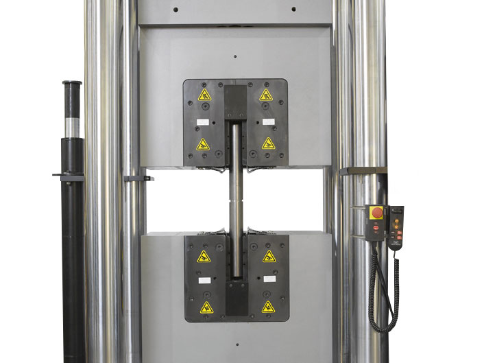
The Pneumatic Wedge Action Grips, available in 100 or 200 kN, provide a convenient method of clamping both large round and flat specimen shapes, up to a 50 mm (2 in) diameter, or flat specimens up to 40 mm (1.57 in) thick respectively. V-face grips are used for round specimens by design and have a reduced area at the center that compromises their ability to absorb high-energy breaks without fracture. This grip uses a split V-face configuration that allows the break energy to be dissipated without damaging the faces.

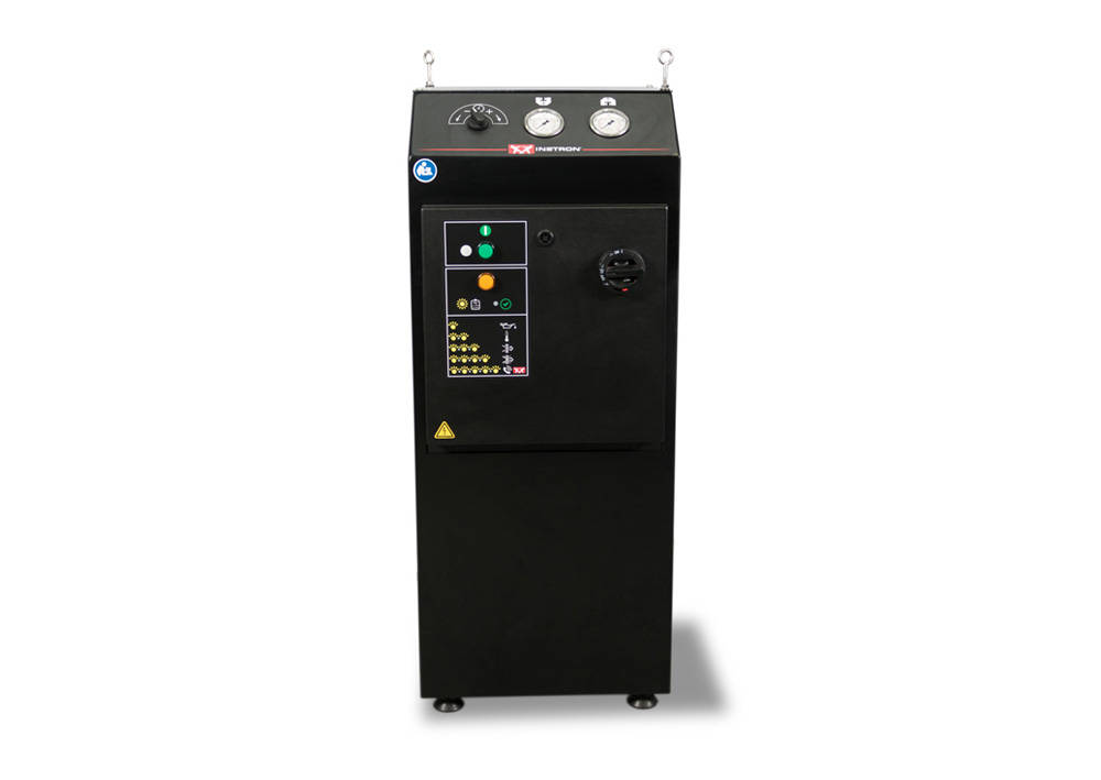
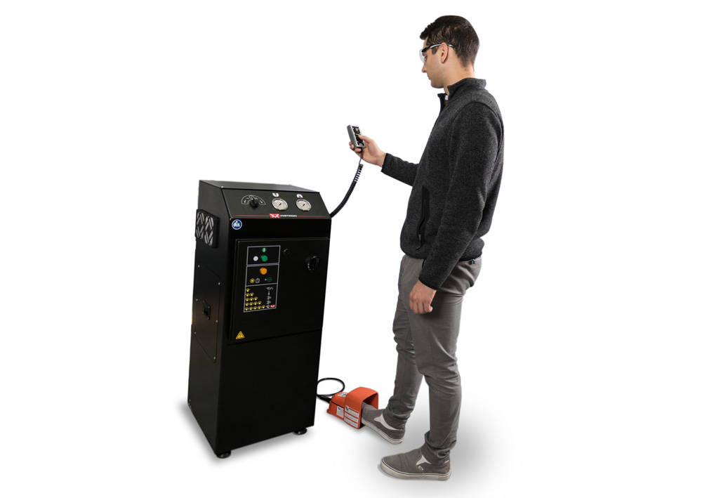

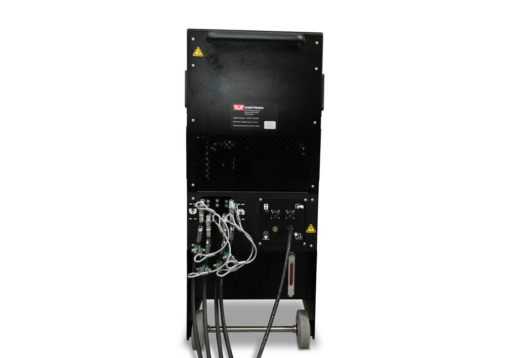
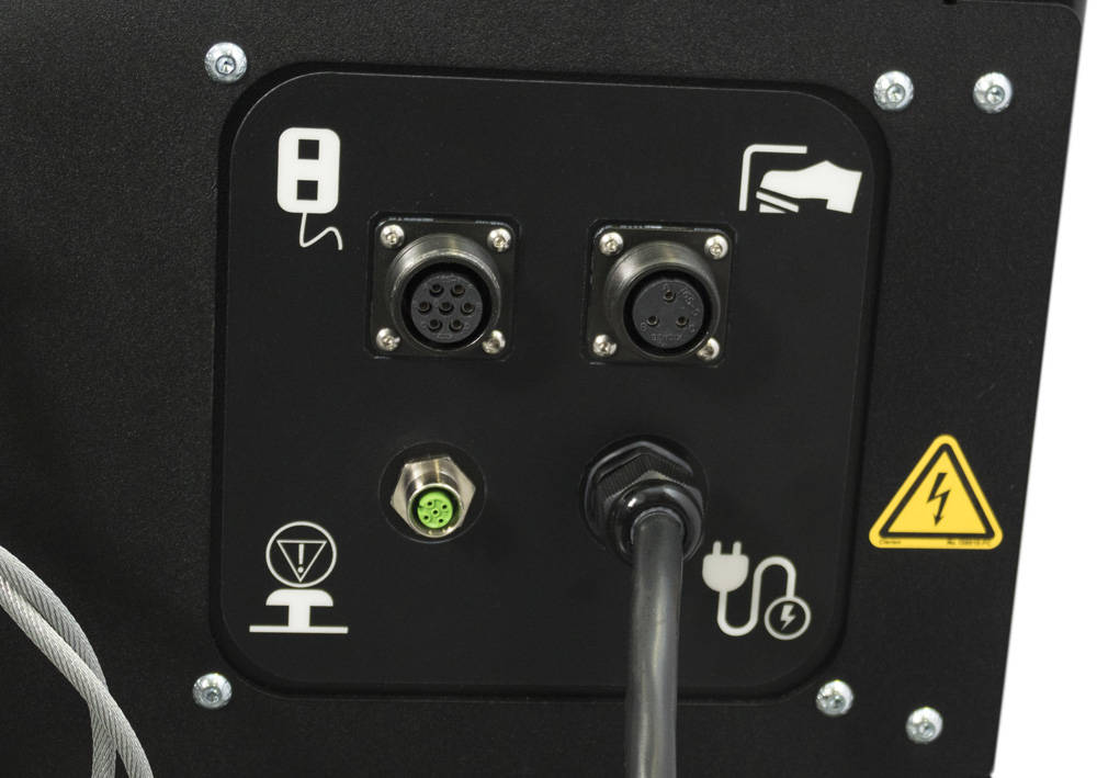
The Instron 2718-550 hydraulic grip pump is designed for continuous 24/7 operation in manual and automated testing systems in industrial environments.
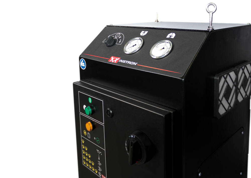
It can be configured to provide a maximum pressure of 207 bar (3000 PSI for use with wedge grips), or alternatively 138 bar (1900 PSI) for use with side acting grips. The unit incorporates two analogue pressure gauges, that are easily visible to the operator from the front of the pump.
The 2718-550 pump is configured to operate with a two stage flow speed, with a higher flow rate up to 69bar (1000psi) to increase productivity. Once clamping the specimen the pressure will then increase to the full pressure at the slower flow rate.
The 2718-550 hydraulic grip pump is activated by a footswitch, while a handset provides close/open functionality of each grip independently. The gripping pressure is easily configured by an electrical adjustment knob located on the front of the pump.
| Grip Type | Static Load Capacity | Catalog No. |
| Advanced Hydraulic Wedge Action Grips | ±130 kN | 2743-401 |
| Advanced Hydraulic Wedge Action Grips | ±312 kN | 2742-501 |
| Advanced Hydraulic Wedge Action Grips | ±600 kN | 2742-601 |
| Hydraulic Dual Side Action Grips | 250 kN | W-5450 |
| Hydraulic Dual Side Action Grips | 600 kN | W-5420 |
The Instron® 2718-550 hydraulic grip pump is designed for continuous 24/7 operation for both manual and automated testing systems in industrial environments
Includes:
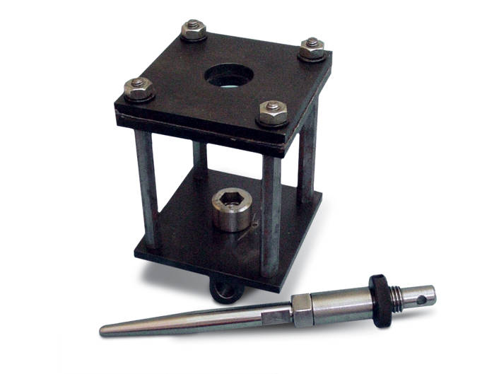
| Accessory Length | 60.3 mm (2.375 in) |
| Lower Fitting | M12x1.75mRH |
| Specimen Diameter | mm (0.375 - 1.000 in) |
| Torque Capacity | 57 Nm (500 in-lb) |
| Upper Effective Length | 47.6 mm (1.875 in) |
| Upper Fitting | M12x1.75mRH |
Capacity: 2 kN
Size: 180 x 180mm (7.1 X 7.1 in) Drip tray.
Lower fitting: 1/2 in clevis, male.
Upper fitting: Requires a food fixture.
Provides a 6 mm clevis, female connection to directly mount other accessories
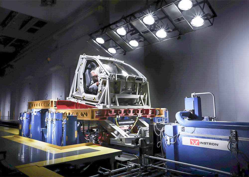
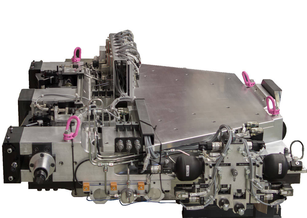
The active controlled pitch simulation load unit offers a significant advantage through more realistic crash simulations and better reproduction of the dummy injury criteria. In a frontal impact, the deceleration and deformation of the vehicle body is almost always accompanied by a movement in the vertical plane. In most cases, this movement is a combination of a rotation around a point in the space in front of the vehicle with an additional vertical movement.
Pitching in crash events directly influences the acceleration and the movement path of the occupant during an impact. These movements together with the strong frontal deceleration during the impact determine the severity of the injury in interaction with the seatbelt and airbag. One focus of security system development is the management of the Head Injury Criteria (HIC) value. Earlier analyzes have shown up to 40% difference between the HIC values of sled tests with and without the possibility of pitch motion simulation. Further influences are found for neck accelerations and belt forces.
The Instron CSA systems with active pitch simulation are currently successfully used by 14 customers.
Back to CSA

Suitable for testing frequencies above 15Hz
| Compatible Frame Models | Isolation mounts for 8801 or 8516 (1 set). For testing frequencies above 15Hz. |
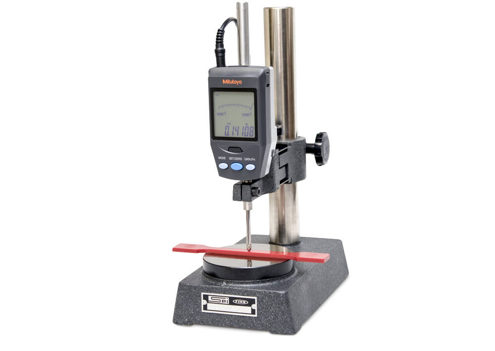
Includes vertically mounted gage probe with indicator, stand, tip set, footswitch, USB interface, and connecting cables.
Range: 0 - 25 mm (0 - 1.0 in)
Resolution: 0.001 mm (0.00005 in)
Instron® testing systems provide an accurate measurement of force during a test, but in order to produce accurate stress results, you must measure the specimen and get the dimensional data into Bluehill® Universal Software. While digital instruments, such as micrometers, can provide accurate measurements, using them properly takes time and requires the operator to manually enter the dimensional data into the software.
Line Voltage: 240 VAC.
| Description | Air Compressor, portable. Line Voltage: 240 VAC. |
Biaxial Extensometer 50 mm Axial Gauge Length providing 2 independent axial and one transverse strain measurement.
Features:
Transverse travel +/- 0.5 mm (Strain range depends on specimen width)
The extensometer provides 2 independent axial outputs along with a single transverse output and requires 3 sensor channels. It has electrical calibration and is self-identifying with 3300, 3400, 4200, 4300, 4400, 4500, 5500, 5800, 5900, 6800, 8500, 8800 Tower, and 8800MT Series Systems. The extensometer is supplied with a single set of conical point specimen contacts.
These bi-axial and averaging axial clip-on extensometers use strain gauges for measurement and are constructed from high-strength aluminum, titanium, and stainless steel. All of the extensometers feature simple, single-handed operation. The extensometer incorporates automatic electrical calibration and transducer recognition including a unique digital serial number.
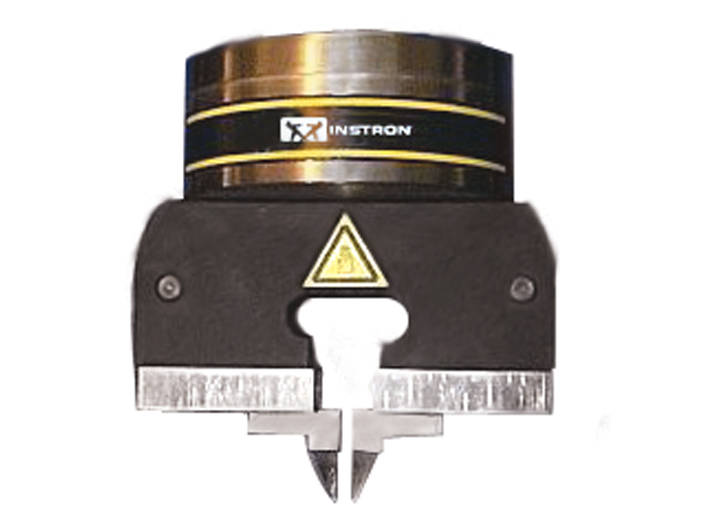
Capacity: 500 N (100 lb, 50 kgf)
Includes a single grip with lead pull jaw faces.
Temperature range: 0°C to 60°C (32°F to 140°F).
Fitting: Type Om (12 mm connection with 6 mm clevis pin). The pneumatic lead pull grip is a parallel action pneumatically operated vice action grip fitted with needle nose jaw faces for lead pull testing.
Requires an automatic air kit.
1 Grip Only.

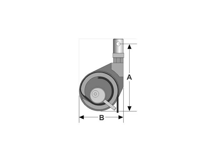
Capacity 36 kN (8,000 lb, 3,600 kg).
Minimum specimen diameter: 0.8 mm (0.031 in).
Maximum specimen diameter: 6.35 mm (0.250 in).
Upper and lower fittings: Type Dm (1.25 in connection with 0.5 in clevis pin).
| Accessory Height |
152 mm (6 in) |
|---|---|
| Accessory Width |
139 mm (5.5 in) |
| Capacity |
36 kN (8000 lbf) |
| Effective Length |
213 mm (8.375 in) |
| Lower Fitting |
1/2 in clevis pin (Type Dm) |
| Specimen Diameter |
0.8 - 6.5 mm (0.0312 - 0.25 in) |
| Temperature Rating |
+10 to +40°C (+50 to +150°F) |
| Upper Fitting |
1/2 in clevis pin (Type Dm) |
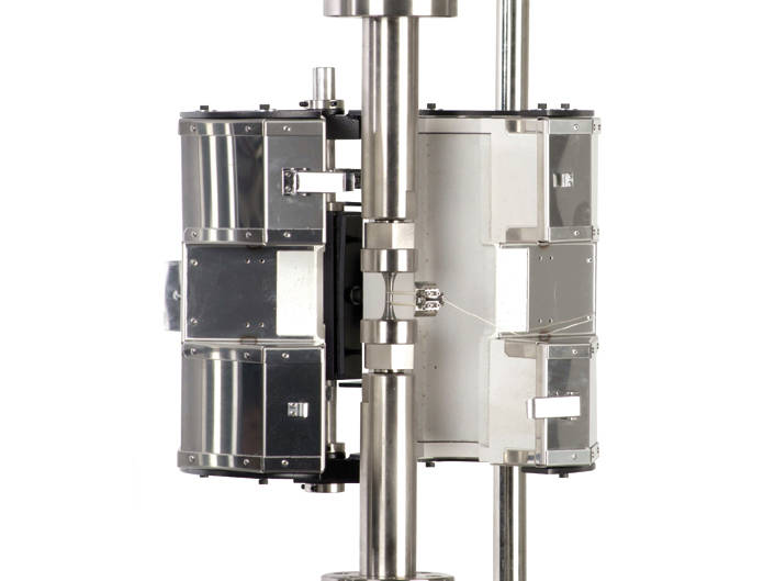
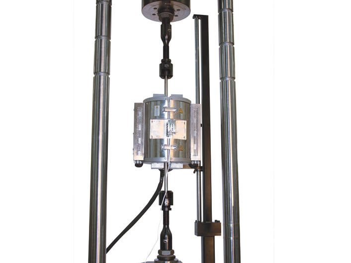

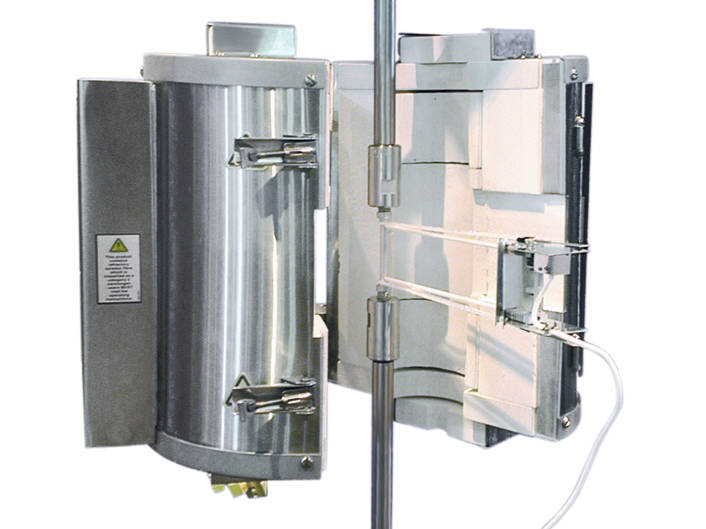
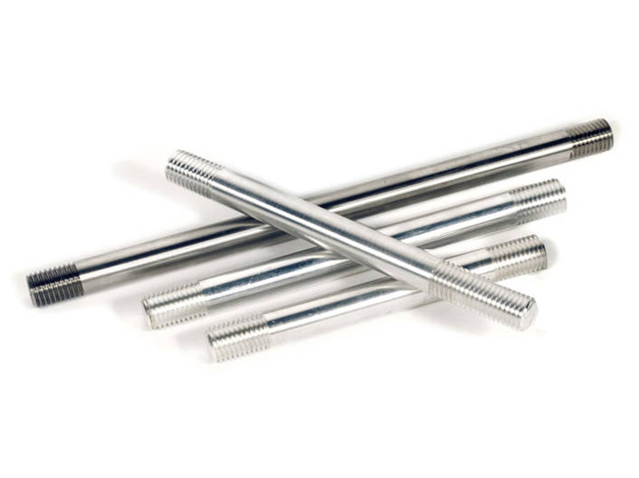
Features:
Includes side port insulation plug for blanking extensometer slot.
Requires temperature controller with thermocouples, support brackets, and top/bottom insulating port plugs (not included)
Z-Direction Tensile.
Fixture includes two test blocks and tabs.
Requires a set of grips, not included.
| Description |
TAPPI T541 Internal Bond Strength of Paperboard. Z-Direction Tensile. |
|---|---|
| Lower Fitting |
Requires upper and lower grip |
| Testing Standards |
TAPPI T541 |
| Upper Fitting |
Requires upper and lower grip |
Fatigue Rated 3 Point Bend Fixture, 100 kN (22 kip) Dynamic Capacity, With 25mm (1.0 in) Diameter Rollers
Includes: One upper roller, 25 mm (0.97 in) Diameter
Requires: fatigue rated adapters
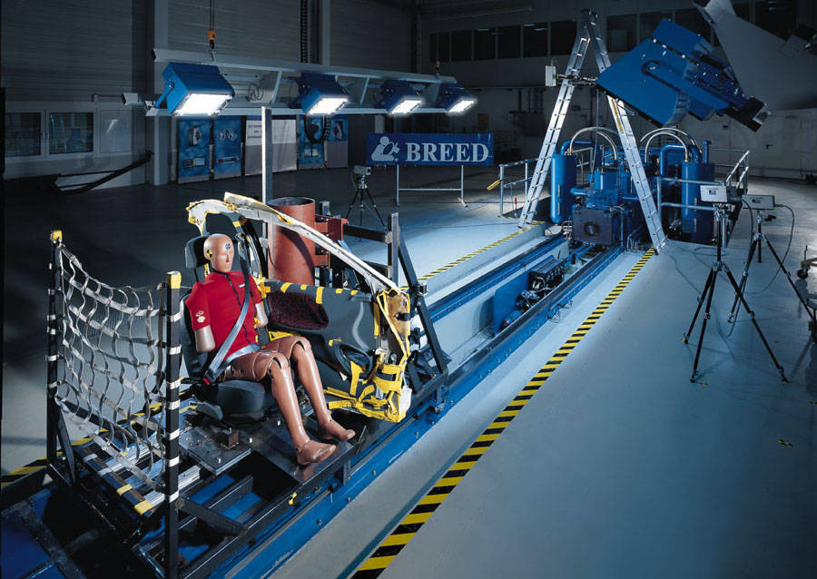
Side crashes are the second most common type of accident. They cause the highest number of critical injuries relative to the accident rate. One reason for this is the spatial proximity of the occupant to the deformation zone. There are different test standards for the side impact. These are the side crash according to ECE-R95 (European standard) and FMVSS-214 (US standard) as well as the tests given in the consumer protection programs. In addition to the actual side impact test, there is also a Pole Side Impact test according to Euro NCAP.
Side-crash simulations on sled systems are carried out for the development of safety restraint systems. These tests begin in an early phase of the development of the whole vehicle. However, prototype parts are not always available at this time and the price of these parts is very high. For the non-destructive sled test, substantially fewer parts are needed than in a destructive test procedure. For example, a seat can be used multiple times, and the door structure with the door trim can last a whole series of tests. Since many of the test components can be re-used, a new test can be set-up in a short time. In addition to the standard side impact simulation unit, Instron can also offer additional sled options for intrusion simulation.
Instron have also successfully integrated proven structures from external partners for intrusion simulation
Back to CSA.
Two chucks are provided
NOTE: Capacity is dependant on specimen geometry. When testing smooth, round specimens, the fixture may not be able to reach full capacity without slippage.
| Accessory Length | 96.5 mm (3.80 in) |
| Lower Fitting | M12x1.75mRH ( ) |
| Specimen Diameter | 9.5 mm (0.375 in) |
| Torque Capacity | 22.5 Nm (200 in-lb) |
| Upper Effective Length | 76.2 mm (3.00 in) |
| Upper Fitting | M12x1.75mRH ( ) |
250 kN (56 kip) Dynamic Capacity, With 100mm (4.0 in) Diameter Upper Roller and 50mm (1.97 in) Diameter Lower Rollers
Requires: fatigue rated adapters
Catalog number 2810-200
Rated capacity 250 kN (25000 kgf, 56250 lbf)
3-point flexure fixture with an optional conversion kit for 4-point loading
150 kN (15,000 kg, 33,750 lbs) capacity T-Grip Bodies
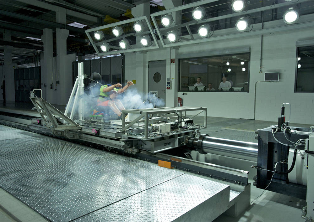
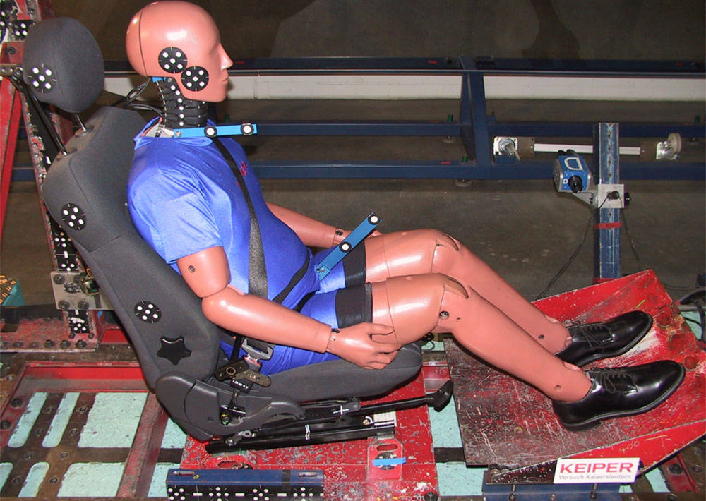
The most common complication after a rear impact and a feared cause of chronic disorders is the whiplash injury. Preventive measures such as the optimization of the seat structure and head rest are proven measures to protect the occupant.
For the development and testing of the interaction between the occupant, the seat and the head rest, appropriate test methods have been developed. The current pulse requirements for rear-end impact tests at low speed are defined in the consumer protection programs (EuroNCAP) or in the USA by third party and legal regulations (IIHS Highway Insurance Institute and FMVSS202a) and other agencies worldwide.
In order to meet the high accuracy requirements of these tests, Instron has developed an expansion package that allows the highly dynamic CSA to be operated extremely precisely at a lower acceleration range. Special low - pressure supplementary equipment reduces the operating pressure of the sled system and thereby optimizes its dynamics according to the requirements of the Whiplash test specifications.
Back to CSA.

载荷:5.0 kN(1,000 lb,500 kg)。
温度范围:-10 °C 至 80 °C(14 °F 至 176 °F)。
试样最大直径:2 mm(0.08 in)。
上下连接件:Dm 型(1.25 in 接口,带 ½ in 销钉)。
需要刚性联轴器和空气自动控制套件或气动脚踏开关
The Instron® pneumatic tire cord grips provide a convenient method for clamping tire cord and braided wire during testing. A guide pin allows for easy loading onto a graduated radius cam, which provides a stress-reduced clamping area on the specimen. The clamping mechanism can be activated either automatically or through a footswitch, which allows for hands-free grip operation enabling the specimen to be held with both hands for easy loading. Pneumatic cord and yarn grips provide selectable clamping force to accommodate different materials and excellent follow-up action that compensates for decay of the holding force due to specimen creep.

Maximum specimen diameter: 13 mm (0.5 in). Capacity: 500 N (100 lb, 50 kg).
Temperature range: 0 °C to 100 °C (32 °F to 212 °F).
Fitting: 6 mm clevis, male.
Minimum specimen diameter: 1.5 mm (.06 in).
Weight: 340 g (.75 lb). Includes one chuck.
Flat-end puncture probes produce a shear stress in the specimen. The force required to cause shearing as the probe penetrates the specimen relates to texture properties such as firmness and hardness.
This guide provides instructions on how to use your components and other frequently performed operating tasks. This manual covers four types of grips: a set of mechanical action wedge grips, manually operated screw grips, a set of chuck grips similar to the chuck on an electric drill, and a set of pincer-action fiber grips. The four types of grips described are covered throughout this manual. The manual is divided into chapters covering description, specifications, installation, operation, maintenance, and parts breakdown. The chapters are subdivided into information about each type of grip.
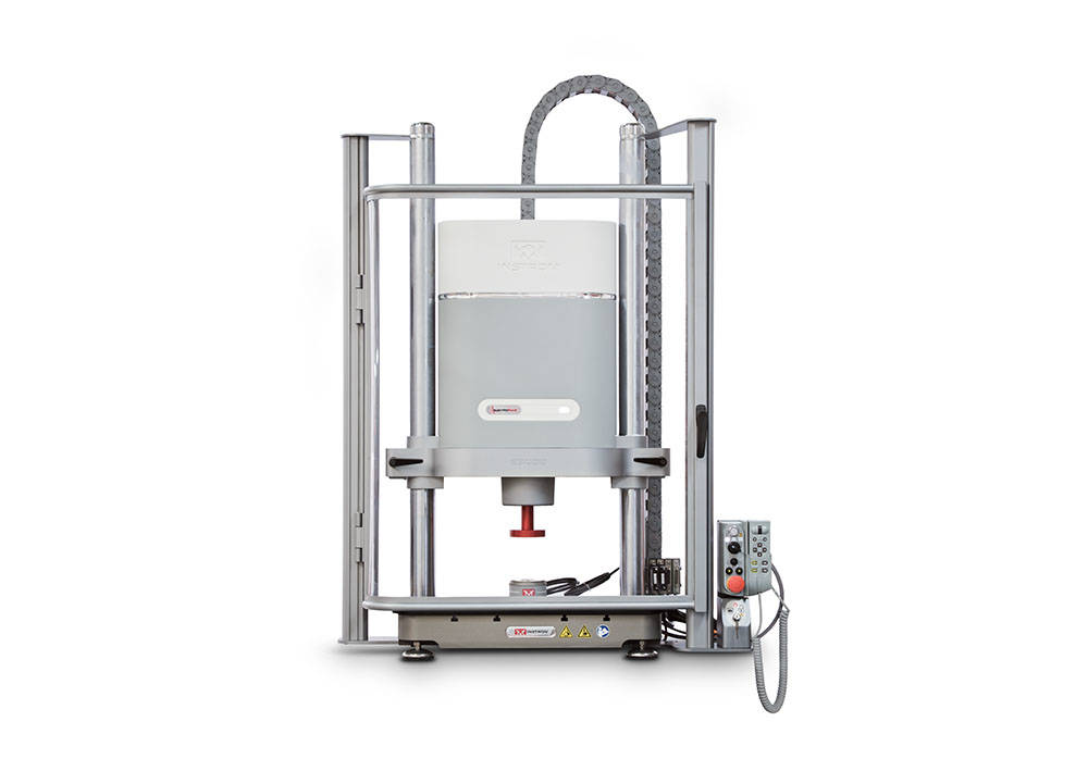
Provides an integrated polycarbonate based guard with a hinged door to prevent operator access to test space when the E3000 is at high power. The guard is also designed to minimize hazards associated with specimen failure.
Includes interlock with ElectroPuls controller to prevent the instrument being switched into high power mode whilst the door is open. Also includes key-switch to over-ride the interlock in extreme cases allowing the machine to operated at high power with the guard door open.
NOTE: Only compatible with 8800 Tower controller
| Accessory Depth - Door Closed | 542 mm (21.3 in) |
| Accessory Depth - Door Open | 1086 mm (42.8 in) |
| Accessory Height - Door Closed | 1283 mm (50.5 in) |
| Accessory Height - Door Open | 1283 mm (50.5 in) |
| Accessory Width - Door Closed | 948 mm (37.3 in) |
| Accessory Width - Door Open | 1234 mm (48.6 in) |
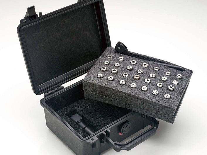
Set includes:

Overview:
EFI software compatibility:
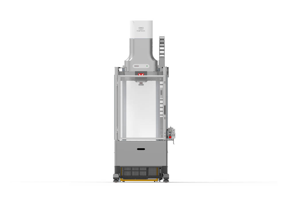

Provides an integrated polycarbonate based guard with a hinged door to prevent operator access to test space when the E20000 is at high power. The guard is also designed to minimize hazards associated with specimen failure.
Includes interlock with ElectroPuls controller to prevent the instrument being switched into high power mode whilst the door is open. Also includes key-switch to over-ride the interlock in extreme cases allowing the machine to operated at high power with the guard door open.
NOTE: Only compatible with 8800MT controller
| Accessory Depth - Door Closed | 601 mm (23.7 in) |
| Accessory Depth - Door Open | 1427 mm (56.18 in) |
| Accessory Height - Door Closed | 1295 mm (50.98 in) |
| Accessory Height - Door Open | 1295 mm (50.98 in) |
| Accessory Width - Door Closed | 1072 mm (42.20 in) |
| Accessory Width - Door Open | 1872 mm (73.70 in) |
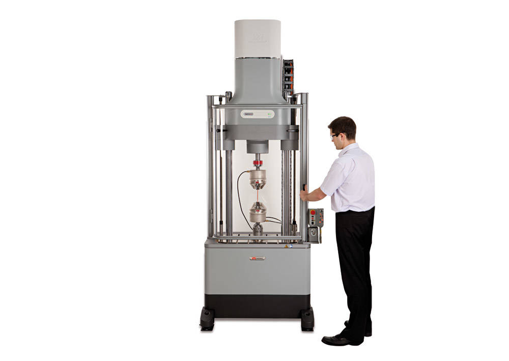
Provides an integrated polycarbonate based guard with a hinged door to prevent operator access to test space when the E10000 is at high power. The guard is also designed to minimize hazards associated with specimen failure.
Includes interlock with ElectroPuls controller to prevent the instrument being switched into high power mode whilst the door is open. Also includes key-switch to over-ride the interlock in extreme cases allowing the machine to operated at high power with the guard door open.
NOTE: Only compatible with 8800MT controller
| Accessory Depth - Door Closed | 496 mm (19.5 in) |
| Accessory Depth - Door Open | 1286 mm (50.65 in) |
| Accessory Height - Door Closed | 1304 mm (51.34 in) |
| Accessory Height - Door Open | 1304 mm (51.34 in) |
| Accessory Width - Door Closed | 1054 mm (41.5 in) |
| Accessory Width - Door Open | 1296 mm (51.02 in) |

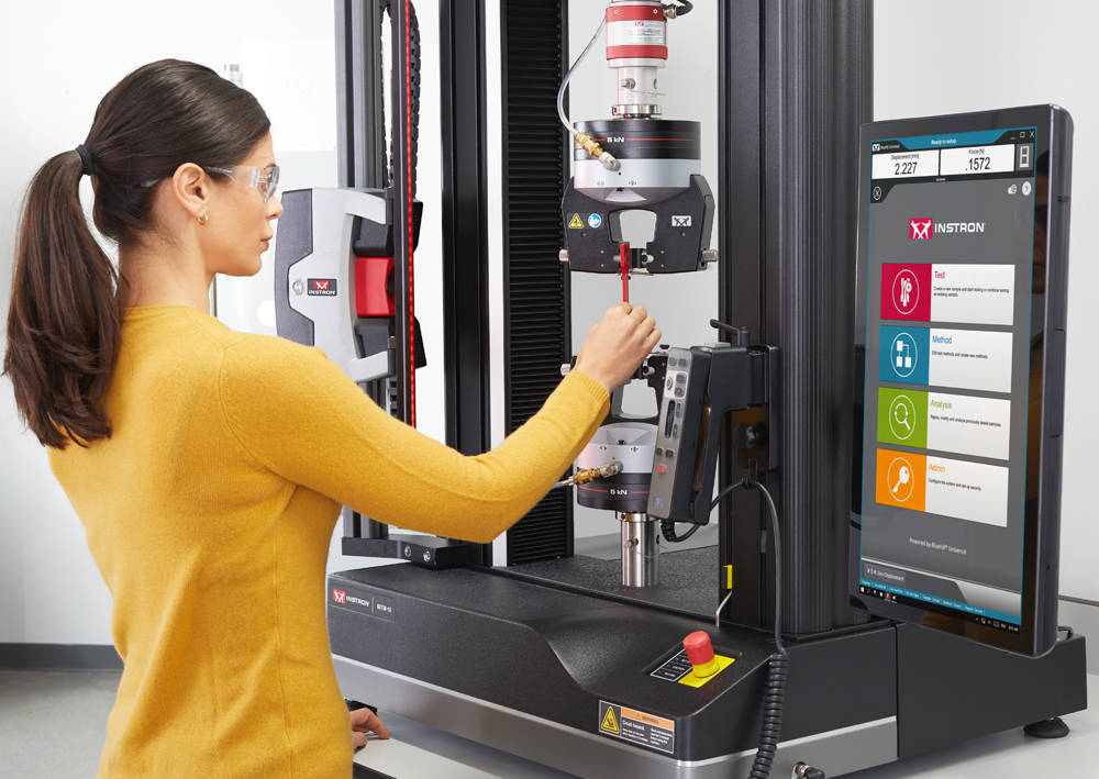
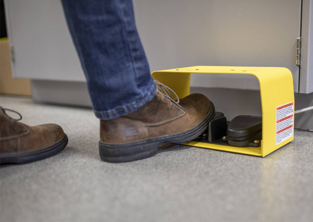
智能闭合空气套件(型号:2701-095) 是系统集成选件,与所有3400和6800系列机架兼容,可监测并控制Instron气动夹具的气压。
| 兼容的机架型号 | 3400 系列, 6800 系列 |
|---|---|
| 连接类型 | ¼” 外径软管 |
| 最大输入压力 | 8.3 bar (120psi) |
| 最大输出压力 | 6.9bar (100psi) |
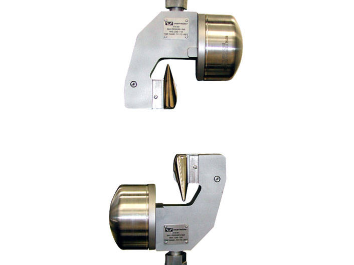
Capacity: 1.0 kN (225 lb, 100 kg).
Temperature range: -70 °C to 260 °C (-100 °F to 500 °F).
Maximum specimen diameter: 3.175 mm (0.125 in).
Upper and lower fittings: pneumatic connection.
Requires pneumatic pullrods and an Automatic Air Control Kit or Pneumatic Foot Switch
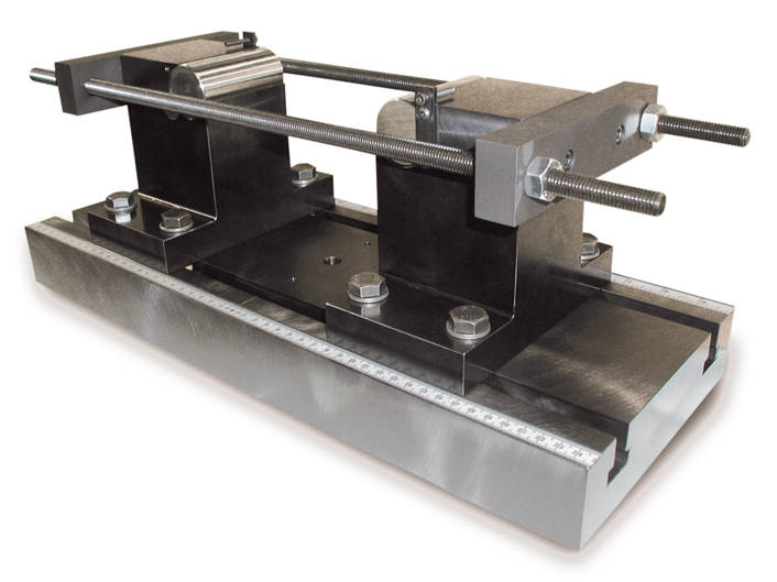

Two types of bend fixtures are available for evaluating the ductility of plate specimens and welded ferrous and non-ferrous materials. The main difference between the two fixtures is in the base, the guided bend test fixture has a fixed span base, while the weld bend test fixture has an adjustable span base.
Both fixtures use plungers or loading struts with a fixed diameter nose for testing a particular specimen thickness. The plungers are attached to the adjustable crosshead using the grip bumper plate or a threaded adapter.
The base is equipped with a dowel hole in the center so that it can be doweled to the compression table and kept from sliding during a test. This also will maintain the alignment of the plunger in relation to base so that the force is applied in the center of the span.
The hardened rollers in the base are captured but free to rotate to allow the specimen to slide as the plunger moves between the rollers. The depth of the base will typically allow up to a full 180 degree bend in the specimen.
The bending force is applied as the specimen is forced against the plunger, either as the base is raised with the table or as the crosshead moves down depending on the frame being used. The plunger forces the specimen into a 180 degree bend against the rollers on the base.
On the weld bend test fixture, one half of the base can be adjusted to one of four different positions to allow for testing different thickness specimens. A separate plunger or strut is required for each thickness specimen, several struts are available depending on the fixture.
Guided bend fixtures have a fixed span base and a single diameter loading strut or plunger to form a complete assembly. Specimen loading is carried the same as with the weld bend fixture though a separate assembly must be purchased for each specimen thickness.
Guided-Bend / Weld Bend Test Fixture, Adjustable Span for "U" bend tests of plane plate or welded flat specimens.
Fixture consists of a t-slot base with adjustable span supports supported by two tie rods.
Fixture specifications:
100kN (22,500 lbf) if installed fully supported
If installed with overhang, capacity is rated per below
Capacity = 100kN (22,500 lbf) where x < 125mm (5 in)
Capacity (kN) = 12,600/x when x > 125 mm
Capacity (lbf) = 111,900/x when x > 5 in
Where x = distance from end of machine loading table
to lower flexure support
Fixture meets the following US and International standards:
ASTM A370-07a, ASTM E190-92, ASTM E290-97a, ANSI/AWS B4.0-98, API 1104, API 5L, AS 2205.3.1, ASME IX 2004, JIS Z2248, GOST 14019 (for specimens 19 to 38.1 mm thick), ISO 5173, ISO 7438, EN ISO 15630-1, EN 910.
Notes:
Includes 0.5, 1.0, 1.5, 2.0 inch diameter loading noses.
CAUTION:
Most standards require loading nose diameters of 4 x specimen thickness. However, some standards allow for other diameter loading noses to be specified locally or as agreed between vendor and customer. It is the customer's responsibility to ensure the proper size loading noses are ordered.
Note: Other size loading noses available individually or in sets as special order.
Metric Loading Nose Set for Guided Bend / Weld Bend Test Fixture. Includes 12, 16, 20, 24, 32, 40, 48 mm diameter loading noses.
CAUTION:
Most standards require loading nose diameters of 4 x specimen thickness. However, some standards allow for other diameter loading noses to be specified locally or as agreed between vendor and customer. It is the customer's responsibility to ensure the proper size loading noses are ordered.
Note: Other size loading noses available individually or in sets as special order.
| Anvil Diameter | 38.1 mm (1.5 in) |
| Capacity | 100 kN (22,500 lbf) |
| Lower Fitting | 12.7 mm (0.5 in) ( ) |
| Specimen Width | up to 76 mm (up to 3.0 in) |
| Support Span | 0-250 mm (0-10 in) |
| Upper Fitting | Refer to W-6810-A/-B ( ) |
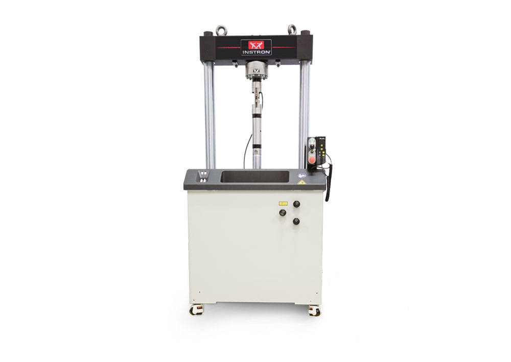
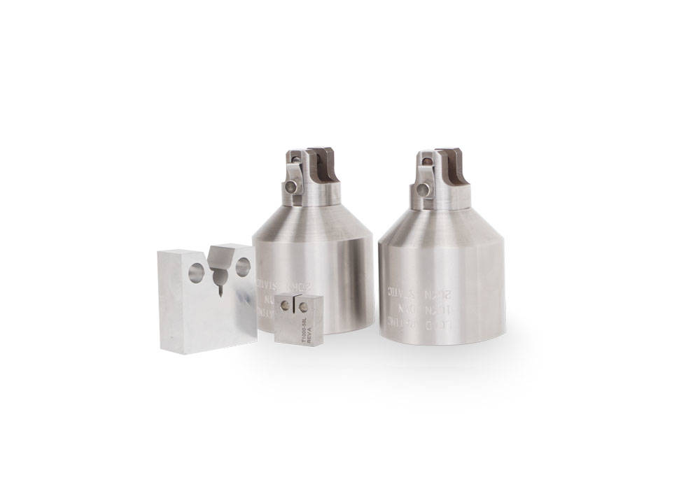

Designed in accordance with international standards such as ASTM E399, E647 & E1820
Rated Capacity: ±10kN Dynamic, 20kN Static
Temperature Range: -50 to 315°C
Includes:
Note: Requires 2780-120 for use with a standard 3119-600 Series Chamber
| Capacity | ±10 dynamic, 20 static kN ( ±2200 dynamic, 4500 static lbf) |
| Specimen Width | 12.5 mm (0.49 in) |
| Testing Standards | ASTM E399, ASTM E647, ASTM E1820 ( ) |

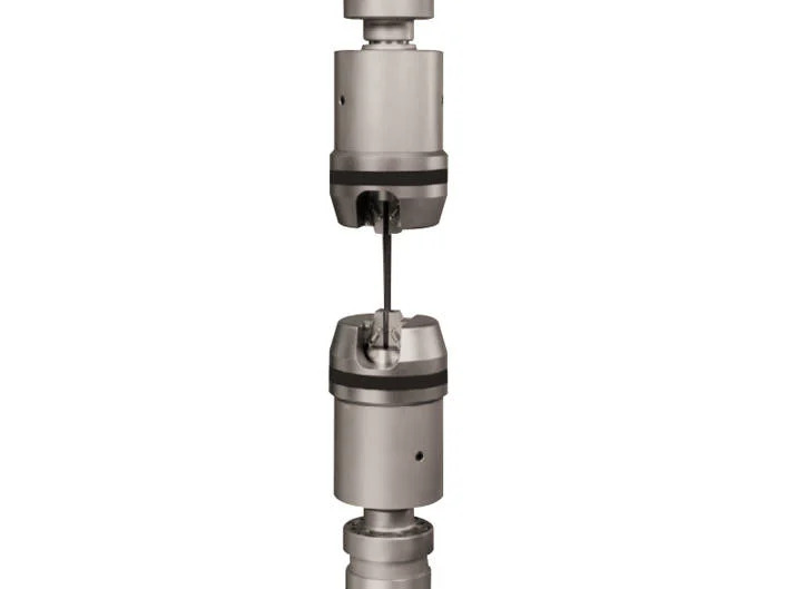
±25kN / ±100Nm Fatigue Rated Hydraulic Wedge Grips for 8874 System
8874 machine requires 8000-049 attachment kit if load cell is fitted to actuator
Requires: Jaw faces (select from 2703-801 to 804 as required) and 207 Bar (3000psi) grip controller
Quantity: 2 grips
±25 kN/100 Nm (5.6 kip/0.6 kip-in) Axial/Torsional Hydraulic Grips catalog number 8260C
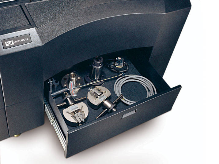
Load Frame Support Base/Extension for Models 4481, 4482, 4484, 4485, 5881, 5882, 5884, 5885, 5885H, 5982, 5984, 5985 load frames. Adds approximately 295 mm (11.6 in) to overall load frame height. An accessory storage drawer is included. For use with single test space, standard height and width load frames only.
Requires stabilizers if ordered with second test space and/or extra height.
Beyond extra height, stabilizers must be bolted to floor.
| Accessory Depth | 757 mm (29.8 in) |
| Accessory Height | 300 mm (12 in) |
| Accessory Width | 1130 mm (44.5 in) |
| Compatible Frame Models | Models 44481, 4482, 4484, 4485, 5881, 5882, 5884, 5885, 5885H, 5982, 5984, 5985 load frames ( ) |

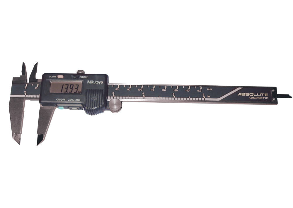
Hand Held Automatic Caliper Measurement System with Carbide Tips. Includes a hand held caliper with digital indicator, carbide tips, footswitch, USB interface and connecting cables.
Range: 0 - 150 mm (0 - 6 in)
Resolution: 0.01 mm (0 .0005 in)
Instron® testing systems provide an accurate measurement of force during a test, but in order to produce accurate stress results, you must measure the specimen and get the dimensional data into Bluehill® Universal Software. While digital instruments, such as micrometers, can provide accurate measurements, using them properly takes time and requires the operator to manually enter the dimensional data into the software.
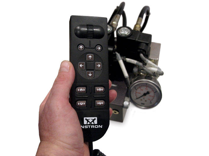
207 Bar (3000psi) Hydraulic Grip Controller And Manifold
Suitable for use on 8801/2/3/4 and 8871/2/4 machines. Provides opening and closing control of the grips with adjustable gripping pressure and handset controls. Includes hoses for connection to the grips and to the system's hydraulic supply.
Designed to be bolted to the table of the testing machine (may require addition of tapped holes).
| Compatible Frame Models | 8801/2/3/4, 8871/2/4, 8511, 8516, and 8502/3/4/5/6. ( ) |
| Description | Hydraulic Grip Controls for Servohydraulic Test Systems ( ) |

100 kN (10,000 kg, 22,500 lbs) capacity T-Grip Bodies.


Capacity: 5.0 kN (1,000 lb, 500 kg).
Incorporates a grooved channel for specimen guidance.
Temperature range: -10 °C to 80 °C (14 °F to 176 °F).
Maximum specimen diameter: 2 mm (0.08 in).
Upper and lower fittings: Type Dm (1.25 in connection with ½ in clevis pin).
Requires a rigid coupling and an Automatic Air Control Kit or Pneumatic Foot Switch
The Instron® pneumatic tire cord grips provide a convenient method for clamping tire cord and braided wire during testing.


The cold bend fixture consists of a base with two infinitely adjustable supports and a plunger (loading strut). Different size bending pins can be ordered to mount on the loading strut to change the radius of the bend. The fixture is designed to bend steel into a "U" shape bend. The finished bend can be near (but never more than) 180 degrees.
Conforms to ASTM A615, A706, A966A and BS4449. The heavy duty base with adjustable span is designed to perform a nominal 90 / 180 degree bend test on # 3 through # 18 (M8-M50) reinforcement bar (rebar), when used with the appropriate bending pins.
The loading strut is mounted in the compression space of a testing machine. The fixture base rests on the machine table and is aligned with the loading strut using a centering pin.
The supports are adjustable to any desired span using a scale that has an origin at the center of the base. Both English and Metric scales are located on the base. The supports clamp to the base by T-slots and use threaded rods to resist deflection during loading. The base is designed to be supported by the machine table or base and can only achieve full capacity when supported with an overhang of 64 mm (2.5 in) or less on each side.
Cold Bend Testing Fixture for bend testing of steel reinforcement bars in general accordance with Specifications; ASTM A615, A706, A996A, & BS4449
A heavy duty table mounted base fixture with an adjustable span is designed for performing the nominal 90 / 180 degree bend tests on #3 through #18 (M8-M50) rebar, when used with the appropriate loading pins. A loading strut, capable of accepting various diameter bending pins, is provided and must be adapted to the adjustable crosshead.
Specifications:
Capacity = 200kN (45,000 lbf) where x < 64mm (2.5 in)
Capacity (kN) = 12,600/x when x > 64 mm
Capacity (lbf) = 111,900/x when x > 2.5 in
(Pin sets based on specification standards and specimen sizes offered separately)
Combined Weight (without bending pins): 83 kg (183 lbs)

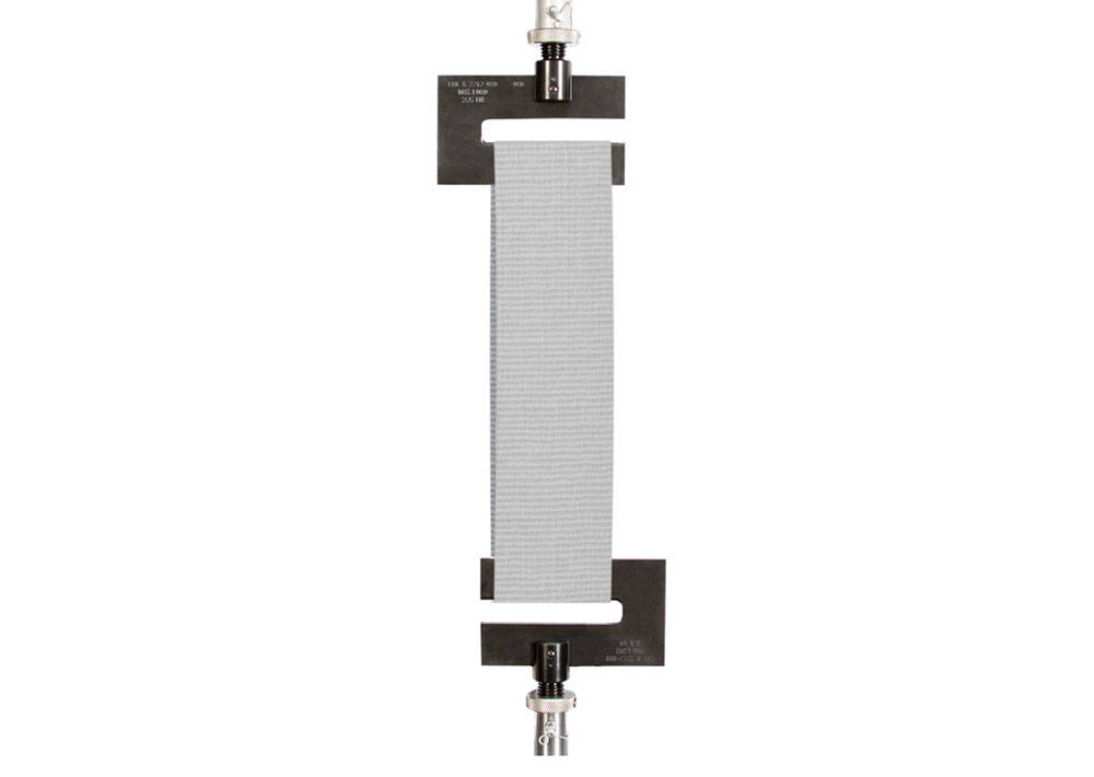
Anvil diameter: 6.4 mm (0.25 in).
For fabric specimens up to 76 mm (3 in) wide.
Per ASTM D-4964.
| Accessory Weight | 0.5 kg (1.1 lb) |
| Accessory Width | 108 mm (4.3 in) |
| Anvil Diameter | 6.4 mm (0.25 in) |
| Capacity | 2.5 kN (560 lbf) |
| Lower Fitting | 6 mm Clevis Pin (Type Om) ( ) |
| Specimen Width | 76 mm (3 in) |
| Temperature Rating | +10 to +40 °C (+50 to +100 °F) |
| Testing Standards | ASTM D 4964 ( ) |
| Upper Effective Length | 97 mm (3.8 in) |
| Upper Fitting | 6 mm Clevis Pin (Type Om) ( ) |
Capacity 600 kN (135,000 lbf, 60,000 kgf)
Specimen Range:
Minimum Specimen Length without the use of an extensometer is 300 mm (11.8 in)
Ambient temperature use only.
Upper and Lower Fittings: Type IIAf RH (M72x3p RH)
Weight Per Grip Body: 327 kg (720 lb)
Grip Body Dimensions W x L x D: 546 x 451 x 203 mm (21.5 x 17.75 x 8 in)
Grip faces sold separately use: W-5197 & W-5198 series grip faces
Configuration Notes:
| Accessory Weight | 327 kg (720 lb) |
| Accessory Width | 546 mm (21.5 in) |
| Capacity | 600 kN (135,000 lbf) |
| Lower Fitting | Type IIAf RH (M72x3P RH) ( ) |
| Temperature Rating | 10-38 °C (50-100 °F) |
| Upper Effective Length | 499 mm (19.625 in) |
| Upper Fitting | Type IIAf RH (M72x3P RH) ( ) |
Capacity: 2 kN
For use with food testing Drip Tray S5400A.
Dimensions: 95 x 95 x 80 mm (3.7 x 3.7 x 3.1 in) height.
Lower fitting: Drip Tray S5400A.
Upper fitting: Requires a food fixture.
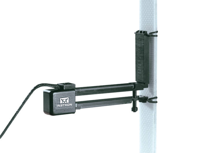
Dynamic Extensometer for direct strain measurement and closed loop strain control. Suitable for tensile, compressive & fatigue testing, the extensometer has a 25mm gauge length with a travel of +12.5mm to -2.5mm giving +50% to -10% strains.
It includes an extender to give a gauge length of 50mm and strain of +25% to -5% strain.
Temperature range: -80C to +200C. Compatible with 8800 and 8500Plus controllers.
May be immersed in acetone, silicone or alcohol.
Wide operating temperature range, from -80 °C to 200 °C (-112 °F to 392 °F)
Designed to meet the requirements of ISO 9513, BS 3846 and ASTM E 83
This guide provides instructions on how to use your system components and controls, procedures for setting limits, calibration and other frequently performed operating tasks.
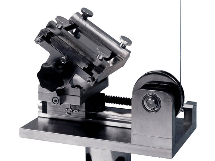
Peel angle: Settable at 30, 45, 60, 90, 120, 135 or 150 degrees.
Fitting: Type Om (12 mm connection with 6 mm clevis pin). Maximum operating temperature : 60°C (140°F).
The miniature variable angle peel fixture is designed for determining the bond and peel strength of microelectronics components like copper runners, films, tapes etc. when peeled from circuit board, substrates or components.
Through the use of a special linkage system, the peel angle is maintained constant during the test.The substrate or component is clamped to the table of the fixture via an "up-down" clamping system.
The moving table is then attached to the actuator or crosshead of the test system. The motion of the actuator or crosshead creates movement on the clamp base but only peel forces are sensed and recorded.
| Capacity | 1 kN (225 lbf) |
| Lower Fitting | 6mm clevis pin (Type Om) |
| Notes | Peel angles of 30,45,60,90,120,135 and 150 deg. |
| Temperature Rating | 10 - 60 °C (50 - 140 °F) |
| Upper Fitting | Requires upper grip |
Capacity: 100 kN (20,000 lb, 10,000 kg)
Upper and lower fittings: Type Dm (1.25 in connection with 1/2 in clevis pin)
Maximum specimen thickness: 40 mm (flat)
Maximum specimen width: 75 mm (flat)
Maximum specimen diameter: 50 mm (round)
Clamping length: 70 mm
Temperature range: ambient only
Requires faces
Includes an air distribution kit with both, 1/4 NPTM (7/16-20), and 1/4 inch hose barb end connections
An Automatic Air Control Kit or Footswitch is recommended
The Pneumatic Wedge Action Grips, available in 100 or 200 kN, provide a convenient method of clamping both large round and flat specimen shapes, up to a 50 mm (2 in) diameter, or flat specimens up to 40 mm (1.57 in) thick respectively. V-face grips are used for round specimens by design and have a reduced area at the center that compromises their ability to absorb high-energy breaks without fracture. This grip uses a split V-face configuration that allows the break energy to be dissipated without damaging the faces.
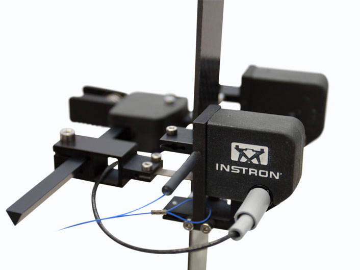

双轴引伸计,轴向标距 25 mm,提供 2 个独立轴向和 1 个横向应变测量。
特点:
横向行程 +/- 0.5 mm(应变范围取决于试样宽度)
该引伸计提供两个独立的轴向输出以及一个横向输出,需占用 3 个传感器通道。它具备电子标定功能,并自动识别 3300、3400、4200、4300、4400、4500、5500、5800、5900、6800、8500、8800 Tower 和 8800MT 系列试验系统。
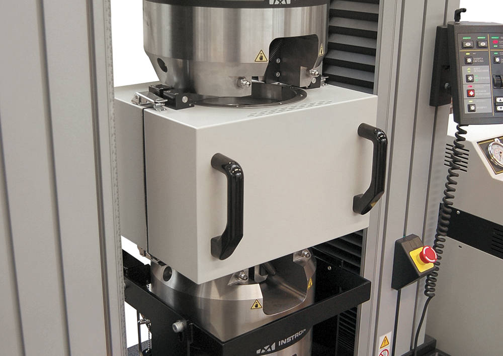

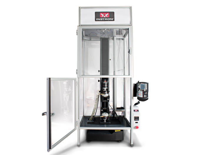
The Custom Solutions group at Instron has been developing accessories for unique thermal applications to meet our customers’ unique needs for decades. Your specimen acts differently in different environments and your testing should match, that's why we will develop thermal testing accessories that allow the ultimate flexibility in testing. Whether your testing in super cooled or extremely heated environments using a new frame or using your current set-up, we will work diligently to understand your goals and ensure they are met or exceeded. Please browse the gallery above to see some of our recent projects.
Click here to see our existing customized thermal solutions specific applications.
Biaxial Extensometer 25 mm Axial Gauge Length providing one averaged axial and one transverse strain measurement.
Features:
Meets ASTM E82 B-1, ISO 9513 grade 0.5 and ISO 527 (annex C)
Transverse Travel: +/-0.5 mm (Strain range depends on specimen width)
The extensometer provides a single averaged axial output along with a single transverse output and requires 2 sensor channels. It has electrical calibration and is self-identifying with 3300, 3400, 4200, 4300, 4400, 4500, 5500, 5800, 5900, 6800, 8500, 8800 Tower, and 8800MT Series Systems.
These bi-axial and averaging axial clip-on extensometers use strain gauges for measurement and are constructed from high-strength aluminum, titanium, and stainless steel. All of the extensometers feature simple, single-handed operation. The extensometer incorporates automatic electrical calibration and transducer recognition including a unique digital serial number.
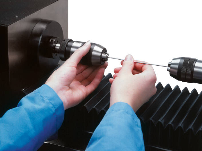

Two chucks are provided.
NOTE: Capacity is dependant on specimen geometry. When testing smooth, round specimens, the fixture may not be able to reach full capacity without slippage.
| Accessory Length | 96.5 mm (3.80 in) |
| Lower Fitting | M12x1.75mRH ( ) |
| Specimen Diameter | 9.5 mm (0.375 in) |
| Torque Capacity | 22.5 Nm (200 in-lb) |
| Upper Effective Length | 76.2 mm (3.00 in) |
| Upper Fitting | M12x1.75mRH ( ) |

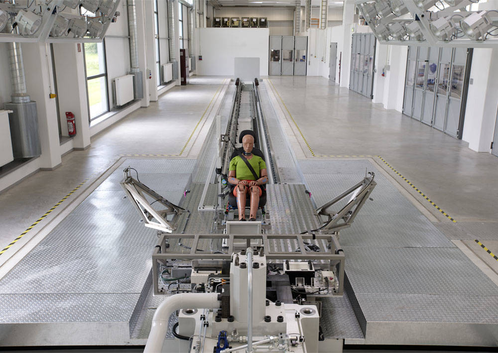
Designed for low mass and high stiffness, the Instron camera outriggers provide a stable mounting point for high speed cameras whilst preserving the performance of the test system.
Includes 4 individual support fixtures for mounting and adjusting cameras on the sled. Proven design maintains access to the test object from both sides of the sled to facilitate test set up and exchange of test components.
Allows installation of up to 4 cameras with 5kg mass each.
Instron® Crack Opening Displacement transducers are designed
specifically to perform standard ASTM and ISO fracture mechanics
tests (both cyclic and static), covering all common specimen
geometries (CT, SEB, Centre Crack, Arc Shaped).
Each model offers class leading linearity, whilst being rugged
enough to withstand the high energy release common in many
of these applications and can be used at both elevated and sub
ambient temperatures.
These gauges comply with requirements laid down in ASTM E399-09.
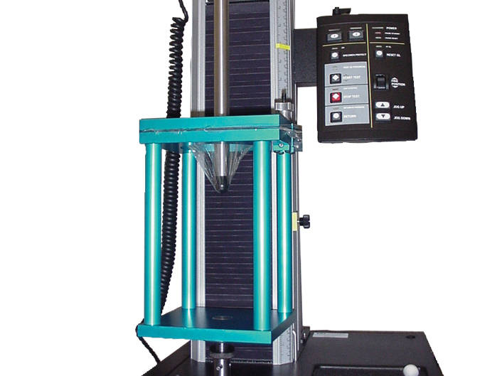

Puncture Fixture per ASTM D5748-95, D4649
Capacity: 4.4 kN (1,000 lbf)
Probe: Tip with 0.75 in pear shaped, Teflon coated with 11 in shaft
Clamping ring inner diameter: 4 in
Lower fitting: Type Dm (1.25 in connection with 1/2 in clevis pin)
Upper fitting: Type Om (12 mm connection with 6 mm clevis pin)
Includes a 6 in square specimen cutting template
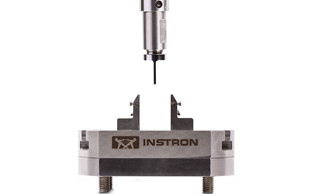
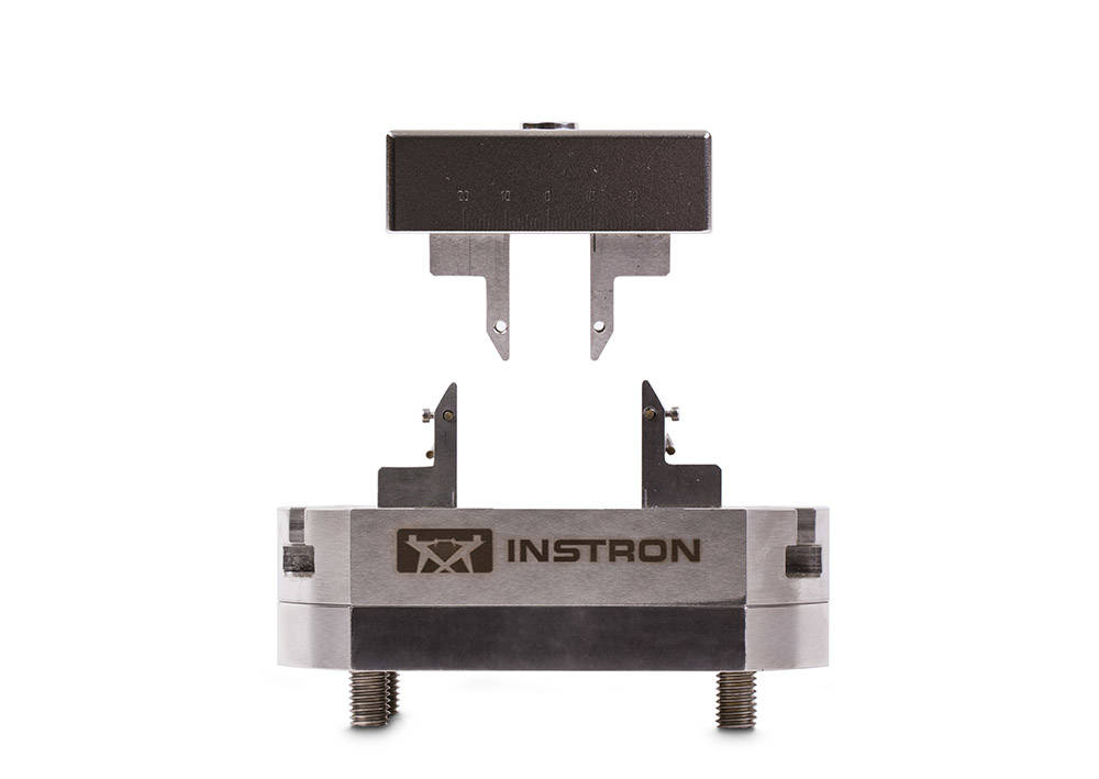
Suitable for both low force dynamic and static testing along with dental standards ISO 9917, ISO 6872, ISO 4049 or ISO 20795 the low-force 3-Point bend fixture is designed to be compatible with ElectroPuls E1000. The specimen is supported on two lower anvils and the load is applied in the center of the specimen by a single upper anvil. The t-slot base allows adjustment of the lower span from 15 - 80mm (0.59 - 3.15in) allowing for variable specimen lengths and is submersible to be compatible with an optional fluid bath and recirculator.
4-Point Bend Fixture Conversion Kit (2810-605): Used to convert 2810-600 from a 3-point to a 4-point bend fixture, the 4-point bend conversion kit has a variable span of 5 - 40mm (0.19-1.57in) and is suitable for both static and dynamic testing. The test specimen is supported on two lower anvils while the load is evenly applied by two upper anvils.
• 3 kN (675 lbf) capacity
• Support span 15 – 80 mm (0.59 – 3.15 in)
• Bend testing of small components, plastics, wood, and composites
• Specimen shapes: Flat and round
• Suitable for both static & fatigue testing
• Compatible with ElectroPuls E1000
The 3-Point bend fixture is designed to easily provide the capability of a 3-point flexure test; it is suitable for both Dynamic & Static testing. The specimen is supported on two lower anvils and the load is applied in the centre of the specimen by a single upper anvil. The fixture has a variable span from 15 – 80 mm (0.59 – 3.15 in).
1.4" gauge length.
| Gauge Length | mm (1.40 in) |
Digital caliper with carbide standard jaws. Resolution of 0.0005" (0.01mm). Accuracy of ±0.001" (±0.02mm). Repeatability of 0.0005" (0.01mm).
Designed to be used in conjunction with Automatic Data Entry Interface listed separately. Qualifies as one (1) device. Includes case.
Note: This measuring device requires an Automatic Data Entry Interface listed separately for direct entry of measurements into software.
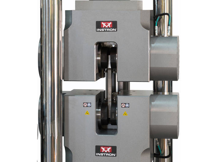
Hydraulic Wedge Grips for 1000KPX/KX Frames
Capacity 1000 kN (225,000 lbf, 100,000 kgf)
Includes:
Upper grip: 648 mm (25.5 in)
Lower grip: 457 mm (18 in)
Combination 1" and 2" Manual Gauge Point Punch.
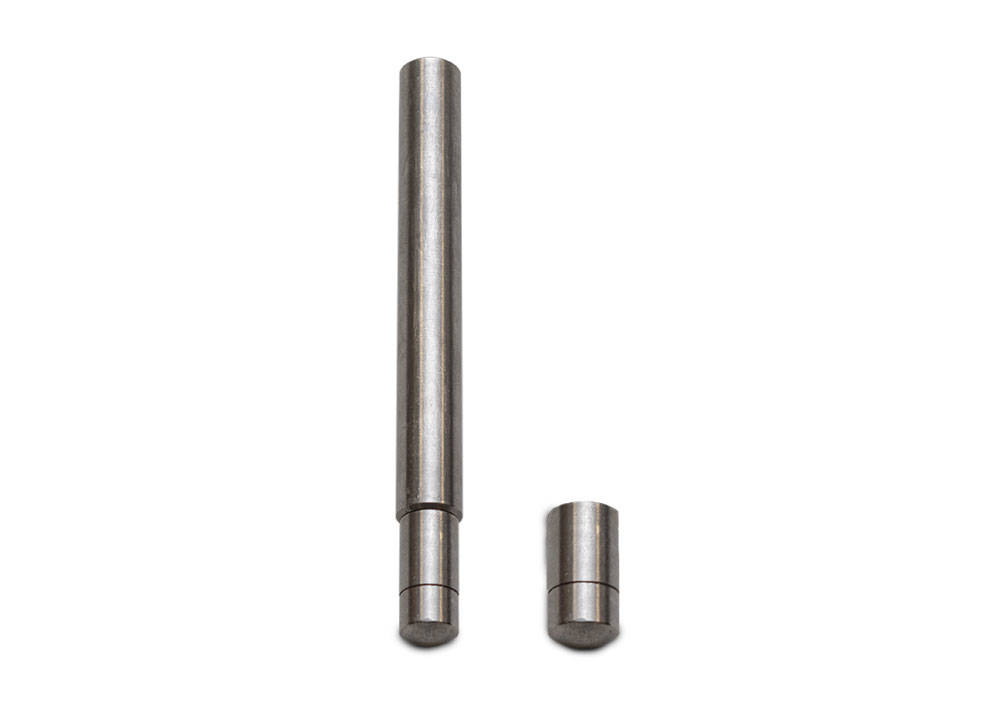
Includes probes of 7.9 mm (0.31 in) and 11.1 mm (0.44 in) diameter.
Upper fitting: Requires Chuck 2830-036.
Lower fitting: Requires optional support plates with Drip tray S5400A and Support Frame S4427A.
Flat-end puncture probes produce a shear stress in the specimen. The force required to cause shearing as the probe penetrates the specimen relates to texture properties such as firmness and hardness.
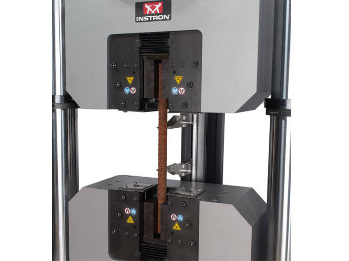
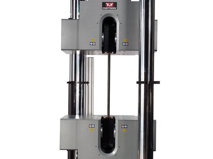
Hydraulic Wedge Action Grips for 1500KX/KPX frames. Capacity 1500 kN (337,500 lbf, 150,000 kgf)
Includes:
Upper grip: 743 mm (29.25 in)
Lower grip: 648 mm (25.5 in)
Capacity: 2 kN
Dimensions: 100 mm x 100 mm (3.9 x 3.9 in) plates.
Four geometries:
Upper fitting: Requires optional probe sets.
Lower fitting: Requires Support Frame S4427A, and Drip Tray S5400A
Designed in accordance with international standards such as ASTM E399, E647 & E1820
Rated Capacity: ±50kN Dynamic, 100kN Static
Temperature Range: -50 to 315°C
Includes:
Note: Requires 2780-120 for use with a standard 3119-600 Series Chamber
Fatigue Compact Tension Fixtures for Servohydraulic machines to test crack growth. POD including 2780-118, 2780-119, 2780-120
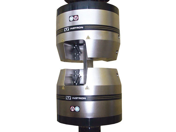
Requires Jaw Faces, 207 bar (3000psi) grip controller and fatigue rated adapters. Quantity: 2 grips
Includes:
| Accessory Length | 60.3 mm (2.375 in) |
| Lower Fitting | M12x1.75mRH ( ) |
| Specimen Diameter | 10 - 24 mm ( in) |
| Torque Capacity | 57 Nm (500 in-lb) |
| Upper Effective Length | 47.6 mm (1.875 in) |
| Upper Fitting | M12x1.75mRH ( ) |
Heavy Duty Load Frame Support Table for All Dual Column Table Top Models, including extra high, extra wide versions.
Provides convenient working height and leg room for operation while seated. Capacity: 679 kg (1500lb) evenly distributed load. Table top dimension: 762 x 1524 mm (30 x 60 in). Height adjustable from 635 to 813 mm (25 to 32 in).
The 2910-056 heavy-duty load frame support table optimizes the performance of tabletop testing systems by providing stability and increased safety. The support table maintains a level working surface, distributes the weight of a dual column electromechanical tabletop load frame, and establishes improved ergonomic conditions for users.
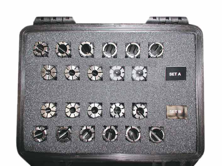
Set includes:
| Accessory Length | 94.6 mm (3.725 in) |
| Lower Fitting | M12x1.75mRH ( ) |
| Specimen Diameter | 6.30 - 14.25 mm (0.2500 - 0.5625 in) |
| Torque Capacity | 225 Nm (2000 in-lb) |
| Upper Effective Length | 82.6 mm (3.250 in) |
| Upper Fitting | M12x1.75mRH ( ) |
Averaging Extensometer 1 in Axial Gauge Length providing a single averaged axial output.
Features:
The extensometer provides a single averaged axial output. It has electrical calibration and is self-identifying with 3300, 3400, 4200, 4300, 4400, 4500, 5500, 5800, 5900, 6800, 8500, 8800 Tower, and 8800MT Series Systems.
These bi-axial and averaging axial clip-on extensometers use strain gauges for measurement and are constructed from high-strength aluminum, titanium, and stainless steel. All of the extensometers feature simple, single-handed operation. The extensometer incorporates automatic electrical calibration and transducer recognition including a unique digital serial number.

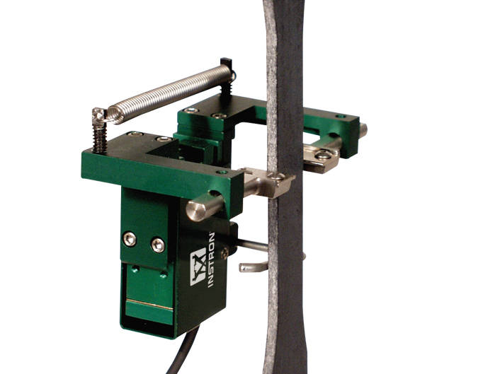
+/- 2.5 mm travel
For general purpose transverse or diametral strain measurement
on axially loaded specimens. Used for measurement of Poisson's ratio
on anisotropic materials like many composites and similar applications.
Specifications:
W-E404 Series Transverse Extensometers are designed for measuring transverse displacements. They are self-supporting on the test specimen and will work on any width or diameter specimen from 0 to 25 mm(1 in).

Capacity: 10 N (2 lb, 1 kgf).
Temperature range: -10 °C to 80 °C (14 °F to 176 °F). Maximum specimen width: 3 mm (0.12 in).
Maximum specimen thickness: 0.8 mm (0.03 in).
Weight without lock ring: 45 g.
Weight with lock ring: 80 g.
Upper and Lower fitting: Type Om (12mm connection with 6mm clevis pin).
Grips have one fixed and one moving face and provide a convenient method for clamping miniature specimens.
A large access area for repeatable and accurate specimen alignment is provided, making the grips suitable for testing of miniature specimens like fine wires, thin films or single filaments.
Foot switch actuation means the operator´s hands are free for accurate specimen placement in the grip. The grip is made of lightweight material and is suitable for both monotonic and low cyclic fatigue testing.
Requires an automatic air control kit.
| Capacity | 0.01 kN (2 lbf) |
| Lower Fitting | 6 mm clevis pin (Type Om) ( ) |
| Temperature Rating | -10 to +80 °C (14 to +176 °F) |
| Upper Fitting | 6 mm clevis pin (Type Om) ( ) |
Provides an integrated polycarbonate based guard with a hinged door to prevent operator access to test space when the E1000 is at high power. The guard is also designed to minimize hazards associated with specimen failure.
Includes interlock with ElectroPuls controller to prevent the instrument being switched into high power mode whilst the door is open. Also includes key-switch to over-ride the interlock in extreme cases allowing the machine to operate at high power with the guard door open.
NOTE: Only compatible with 8800 Tower controller
| Accessory Depth - Door Closed | 481 mm (18.9 in) |
| Accessory Depth - Door Open | 886 mm (34.9 in) |
| Accessory Height - Door Closed | 876 mm (34.5 in) |
| Accessory Height - Door Open | 876 mm (34.5 in) |
| Accessory Width - Door Closed | 835 mm (32.9 in) |
| Accessory Width - Door Open | 932 mm (36.7 in) |
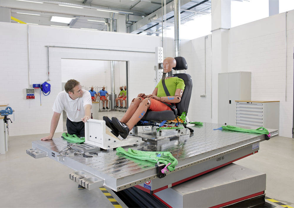

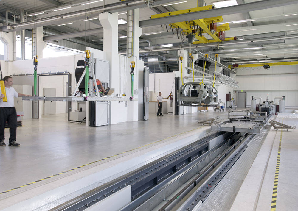
The quick clamping mechanism allows standardized mounting of any type of structures to the sled. The installation and set-up of the test object can be carried out in preparatory rooms on pallets. The configured pallets are transported to the test sled by a crane and clamped on the sled in just a few minutes.
The pallets can be standardized universal pallets for component tests or pallet frames for the construction of reinforced body shells. Standardized pallets may be used or customers may adapt their own fixtures and test bucks to the Instron quick-clamp system.
Furthermore, the pallet design with the necessary interfaces to the INSTRON quick clamping mechanism can be developed by the test laboratory.
Back to CSA.


Dynamic Extensometer for direct strain measurement and closed loop strain control. Suitable for tensile, compressive & fatigue testing, the extensometer has a 10mm gauge length with a travel of ±1mm giving ±10% strain.
It includes a 15mm extender to give a gauge length of 25mm and ±4% strain and a 40mm extender to give a gauge length of 50mm and strain of ±2%.
Temperature range: -80C to +200C. Compatible with 8800 and 8500Plus controllers. May be immersed in acetone, silicone or alcohol.
Wide operating temperature range, from -80 °C to 200 °C (-112 °F to 392 °F)
Designed to meet the requirements of ISO 9513, BS 3846 and ASTM E 83
This guide provides instructions on how to use your system components and controls, procedures for setting limits, calibration and other frequently performed operating tasks.
+/- 0.10 in travel
For general purpose transverse or diametral strain measurement
on axially loaded specimens. Used for measurement of Poisson's ratio,
on anisotropic materials like many composites and similar applications.
Specifications:
W-E404 Series Transverse Extensometers are designed for measuring transverse displacements. They are self-supporting on the test specimen and will work on any width or diameter specimen from 0 to 25 mm(1 in).
Dynamic Extensometer for direct strain measurement and closed loop strain control. suitable for tensile, compressive & fatigue testing, the extensometer has a 12.5mm gauge length with a travel of ±2.5mm giving ±20% strain.
It includes a 12.5mm extender to give a gauge length of 25mm and ±10% strain and a 37.5mm extender to give a gauge length of 50mm and strain of ±5% strain.
Temperature range: -80C to +200C. Compatible with 8800 and 8500Plus controllers. May be immersed in acetone, silicone or alcohol.
Wide operating temperature range, from -80 °C to 200 °C (-112 °F to 392 °F)
Designed to meet the requirements of ISO 9513, BS 3846 and ASTM E 83
This guide provides instructions on how to use your system components and controls, procedures for setting limits, calibration and other frequently performed operating tasks.
Capacity: 2 kN
Dimensions: 57.32 mm (2.26 in) diameter x 86 mm (3.39 in) long.
Fitting: 6 mm clevis, male.
| Lower Fitting | Requires suitable lower anvil or support plate ( ) |
| Upper Fitting | 6 mm Clevis Pin (Type Om) ( ) |
Supports data acquisition for only one transducer (strain gage bridge, LVDT, or +/-10V BNC input).
Includes:
Note: Not recommended for customer installation to an existing tower. Always include service time when quoting as an accessory.
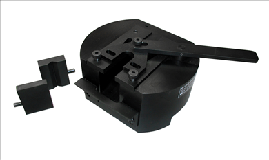
150 kN (15,000 kg, 33,750 lb) capacity T-Grip Bodies
Digital micrometer with flat anvils for measuring outside diameter and thickness. Resolution of 0.00005" (0.001mm). Accuracy of ±0.0001" (±0.002mm). Designed to be used in conjunction with Automatic Data Entry Interface listed separately. Qualifies as one (1) device. Includes case.
Note: This measuring device requires an Automatic Data Entry Interface listed separately for direct entry of measurements into software.
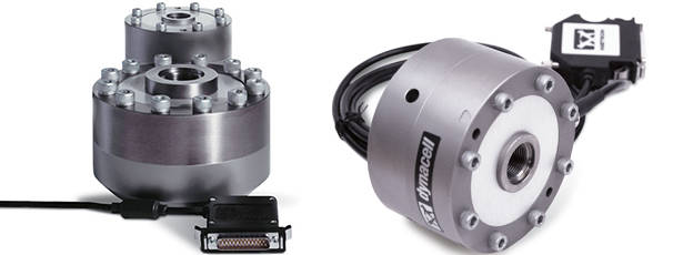
During tests carried out on servohydraulic machines, elements of the system are subject to acceleration. As a result, in addition to the force applied to the specimen, the load cell also reads forces resulting from its own movement and the mass of the grips and fixtures attached to it.
Dynacell is the world's first truly dynamic load cell, designed from the outset for measuring dynamic loads. Dynacell introduces the following advantages:
Dynacell utilises an accelerometer right at the heart of the load cell, directly on the load axis. This removes the risk of errors in the acceleration reading resulting from off-center loading.
This has the following advantages:
The conditioning of the acceleration signal from the Dynacell is handled as standard in the FastTrack 8800 electronics, and is set-up automatically when the system is autotuned. This means that time is saved and operator errors reduced.
For users who wish to do this themselves, they have the option to switch this feature on or off and set the correction factor manually.
The resulting signal is then subtracted from the load cell signal to produce the true force on the specimen.
Application Range
Products
| Item Name | Cat # |
|---|---|
| Dynacell - Dynamic Load Cell ±250 N (±56 lbf) | 2527-131 |
| Dynacell - Dynamic Load Cell ± 2000 N (± 450 lbf) | 2527-129 |
| Dynacell - Dynamic Load Cell ± 5000 N (± 1125 lbf) | 2527-153 |
| Dynacell - Dynamic Load Cell ±1 kN (±225 lbf) | 2527-130 |
| Dynacell - Dynamic Load Cell ±10 kN (±2250 lbf) | 2527-102 |
| Dynacell, Dynamic Load Cell; +/-25 kN (5620 lbf) | 2527-101 |
| Dynacell, Dynamic Load Cell; +/- 50 kN (11250 lbf) | 2527-100 |
| Dynacell, Dynamic Load Cell; +/-100 kN. (22500 lbf) | 2527-111 |
| Dynacell, Dynamic Load Cell; +/- 250 kN (56250 lbf) | 2527-115 |
| Dynacell, Dynamic Load Cell; +/- 500kN (110 kips) | 2527-125 |
| Dynacell, Dynamic Load Cell; +/- 1MN (220 kips) | 2527-120 |
| Dynacell, Dynamic Load Cell +/-2.5MN (550 kips) | 2527-140 |
Axial Clip-on Extensometers
电动泵为内置储气罐充入压缩空气。夹具通过可选配的空气套件与空压机相连,该套件还可额外选配用于控制夹具闭合的脚踏开关。
夹具的气压可通过空压机配备的压力调节器进行调节。过滤器可确保为夹具提供洁净空气。
| 产品名称 | 目录编号 |
|---|---|
| 空压机,便携式;电源:240 VAC | 2810-060 |
这些套筒驱动装置可将任意 0.5 in 驱动的套筒装置或附件直接连接至 MT 系列试验系统的扭矩传感器和 / 或输出轴。更小规格的驱动套筒可通过变径适配器进行连接。
提供多种尺寸的英制和公制套筒组,适用于测试带六角接口的紧固件或成品。这些驱动装置可用于测试锁紧式和非锁紧式紧固件的运行扭矩、对承受扭转载荷的紧固件进行强度验证测试,或检测棘轮、扭矩扳手及其他类型工具的扭转阻力。
套筒驱动装置通过螺纹连接或螺栓固定在 MT 系列试验系统的输出轴和 / 或扭矩传感器上。锁紧螺母用于将带螺纹的转接头固定到位,并在双向测试过程中保持其锁紧状态。
套筒随后被压装到转接头上,并通过一个弹簧式滚珠进行固定,就像那些商用棘轮一样。测试螺栓和螺母试样时可使用两个套筒;若需在必须固定于定制夹具的部件中拧紧或松开紧固件,则只需使用一个套筒。
| 产品名称 | 目录编号 |
|---|---|
| 0.5 in 套筒驱动扭转夹具,英制 | W-MT03 |
| 0.5 in 套筒驱动扭转夹具,公制 | W-MT03-M |
Instron 手动楔形夹具可用于静态或动态材料测试应用,可互换的楔形夹面适用于扁平或圆柱形试样。
该夹具的设计旨在确保测试试样能够被稳固夹持,同时不会对试样施加轴向力。这一效果是通过采用仅相对于试样作水平方向移动的夹面来实现的。
每个夹具均为手动操作,通过夹具本体相对于楔形夹面的移动来施加夹持力。这种移动是通过拧紧夹头底部的四个圆柱头内六角螺钉实现的。
每个夹面通过两个拉伸弹簧固定在夹具本体中,测试结束后,这些弹簧可使夹面自动松开试样。
夹具本体的楔形区域装配有夹面导向装置,以确保各夹面面始终保持相互垂直,并与试样保持垂直状态。
| 项目名称 | 目录# |
|---|---|
| 手动疲劳楔形夹具(+/- 100 kN) | 2743-402 |
| 2742-102 ±1 kN 手动疲劳楔形夹具 | 2742-102 |
| 2742-316 ±10 kN ±100 Nm 手动疲劳楔形夹具 | 2742-316 |
| 2742-206 ±3 kN ±25 Nm 手动疲劳楔形夹具 | 2742-206 |
T 型夹具体的载荷范围为 22.2 至 150 kN(5,000 至 33,750 lbf)。这些经济实用且用途广泛的组件旨在简化试样的装拆过程,这一特性能够节省时间、减轻操作人员的疲劳感,旨在提高重复测试操作中的工作效率。
T 型夹具体设计为可适配液压万能试验系统和电子万能试验系统(UTM),其大多采用前开式设计,便于试验样品的轻松夹持与取出。
多种可互换夹面可安装于 T 型夹具体中,能够适配不同尺寸的平板试样和圆柱形试样。为提升操作便捷性,下夹座的锁定机构可使夹面保持张开状态,从而实现单手装样。
上下夹具的主体结构相同。每个夹持器主体都设有一个凹槽,用于放置一对夹面,并采用楔形设计。这种楔形设计能在试样承受载荷时使夹面进一步收紧,从而减少试样打滑。
T 型夹具提供两种类型的驱动方式:杠杆/弹簧式或螺钉式。
所有规格的 T 型夹具体均配备杠杆 / 弹簧驱动装置,该装置通过杠杆实现夹面在夹持区域的升降,并通过弹簧为试样提供初始夹持力。装载试样时,操作人员需将下夹面锁定在张开状态,随后打开上夹面,将试样的上半部分放入其中。待试样被上夹面牢固夹紧后,操作人员将试样的下半部分放入下夹面,再解锁夹面,此时夹面会提供夹持力并固定试样,以便开始测试。
在螺旋式驱动装置中(配备于 20,000 lb 规格的型号),手动螺旋作动缸通过手动转动手柄来实现夹面的开合。这种螺旋式驱动能提供更稳固的初始夹持力,非常适合用于打滑现象频发的硬质材料测试。
| 产品名称 | 目录编号 |
|---|---|
| 楔形 T 形夹具(杠杆驱动式);载荷范围 150 kN | W-5057-A |
| 楔形 T 形夹具(杠杆驱动式);载荷范围:100 kN | W-5021 |
| 楔形 T 形夹具(杠杆驱动式);载荷范围:150 kN | W-5151 |
| 产品名称 | 目录编号 |
|---|---|
| ElectroPuls E1000 测试设备的安全防护装置 | 1300-301 |
| ElectroPuls E3000 测试设备的安全防护装置 | 1300-304 |
| ElectroPuls E10000 测试设备的安全防护装置 | 1300-303 |
| ElectroPuls E20000 测试设备的安全防护装置 | 1300-305 |
| ElectroPuls 测试设备的高刚度支撑台 | 1300-311 和 1300-315 |
弯曲工装可用于进行多种弯曲试验和断裂韧性粘合试验,包括测定弯曲模量、弯曲强度和弯曲屈服强度。
这款三点弯曲工装安装简便,借助可选配的转换套件进行改装后,即可实现四点弯曲试验功能。
底座可调节,以适应不同跨距的试样。试样的挠度可以通过横梁位移来测量,若要进行更精确的测量,则可使用带夹具的引伸计配合中跨直接测量挠度计的压头进行测量。
试样由两个精密加工的底座(可自由旋转或固定)支撑,砧座的半径是确定的。力施加在中心位置(三点弯曲)或中心两侧特定距离处(四点弯曲)。支撑梁沿长度方向标有公制刻度,便于底座的准确定位,且底座相对于中心线对称分布。
这一特性同样适用于四点加载梁及底座。
| 产品名称 | 目录编号 |
|---|---|
| 100 kN 弯曲工装,三点疲劳 | 2810-181 |
| 250 kN 弯曲工装,三点疲劳 | 2810-200 |
| 500 kN 弯曲工装,三点疲劳 | 2810-250 |
| 20 kN 弯曲工装,三点疲劳 | 2810-500/505 |
| 3 kN 弯曲工装,三点疲劳 | 2810-600/605 |
| 产品名称 | 目录编号 |
|---|---|
| 用于 15 Hz 以上测试频率的气垫隔振器 | 1300-008 |
| 8801 或 8516 的隔离垫支座(1 套);用于 15 Hz 以上的测试频率。 | 1300-009 |
纸张和纸板测试在制浆造纸行业中至关重要,因为其应用范围广泛,不同应用场景对其有着多样的要求。
在印刷领域,纸张的形态包括单张纸或卷筒纸(纸卷),其抗拉强度和延伸率特性必须满足客户的严格要求。在包装领域,则需对瓦楞纸进行测试,以测定其边缘抗压性能。
| 产品名称 | 测试标准 | 目录编号 |
|---|---|---|
| TAPPI T541 纸板内部粘合强度。Z 向拉伸。 | TAPPI T541 | S1-11814 |
这类通用钻头式卡盘夹具可用于夹持圆柱形、六角形或三角形试样。标准套装有无键钻型和键控钻型两种类型,能适配多种规格的试样。
无键设计可实现试样的快速夹持与释放。其套筒握持舒适稳固,便于手动拧紧卡盘。
键控设计能快速便捷地紧固试样和快速无粘连地取下试样。
卡盘夹具通过螺纹连接或螺栓固定在 MT 系列机架的输出轴和 / 或扭矩传感器上。
在扭转测试中,卡盘夹具旋转闭合来夹紧试样。这类夹具的夹面延伸长度远超卡盘前端,可适配多种线材、电缆及圆柱形试样。键控钻型和无键钻型卡盘均能夹持不同直径的试样,并配有用于安装在 MT 系列机架上的连接件。
| 产品名称 | 目录编号 |
|---|---|
| 0.375 in 键控钻型卡盘 | W-MT01-B |
| 0.375 in 无键钻型卡盘 | W-MT01 |
主要的夹具组件包括夹具驱动器、楔形夹头、夹具连接法兰和夹面。
夹具驱动器通过相对夹面移动夹头来施加夹持力,从而使夹面夹紧试样。
夹具驱动器还集成了三组防转滑块,可将执行器施加的扭矩传递至夹具及试样。夹面采用锯齿状或 V 型槽设计,以适配平板或圆柱形试样。
| 产品名称 | 目录编号 |
|---|---|
| 适用于 8874 试验系统的 25kN / 100Nm 疲劳额定液压楔形夹具 | 8260C |
为了输入来自可选配引伸计或其他应变传感器的信号,8800 控制器需要配备一个应变通道。该应变通道可为应变片和线性可变差动变压器(LVDT)装置提供激励和信号调理,同时也能接收 0-10V 的高电平模拟输入信号。
有两个版本可用,一个仅用于监控,另一个可用于监控和控制。这是可选应变测量传感器向 FastTrack 8800 控制器输入应变数据所必需的。
应变通道为应变片和 线性可变差动变压器(LVDT)装置提供激励和信号调理,并且还可以接受高电平 0-10V 模拟输入信号。
有两个版本可用,一个仅用于监控,另一个用于监控和控制。
为了输入来自可选配引伸计或其他应变传感器的信号,8800 控制器需要配备一个应变通道。
| 项目名称 | 目录编号 |
|---|---|
| 传感器通道 - 8800MT 系列(控制和数据采集) | 8800-621 |
| 传感器通道 - 8800MT 系列(仅数据采集) | 8800-622 |
可采购多种试样测量装置,以实现数字测量、带自动数据录入功能的数字测量或手动测量。
使用数字测量设备如数显卡尺、千分尺等数字仪器进行试样测量,可获得精确的测量结果。这些设备有多种测量范围可供选择。若配备自动数据输入接口,设备可将数字测量结果直接传输至用于运行试验的控制软件,无需手动输入。这些设备与 Bluehill®、Merlin™、Partner™ 及 Series IX™ 高级材料试验软件兼容。
多种手动测量设备可用于试验后测定试样的延伸率或断面收缩率。延伸率标尺(有标准型和伸缩型可供选择)用于测量平板试样的延伸率,而断面收缩率量规则用于测量圆柱形试样的断面收缩率。
通过数据自动输入接口可实现测量设备到软件的数字化数据传输。该接口负责将带有 RS-232 输出的设备通过连接线缆传输数据,并将其路由至控制软件。
断面收缩率测量设备和延伸率测量设备的操作方式类似于直尺或滑动标尺。
| 产品名称 | 目录编号 |
|---|---|
| 与 Partner 搭配使用的数据自动输入接口 |
W-3276-B |
| 带尖爪卡尺,0-150 mm(0-6 in),带数据线 |
W-3275-Q |
| 标准爪卡尺,0-150 mm(0-6 in),带数据线 |
W-3275-N |
| 标准爪卡尺,0-300 mm(0-12 in),带数据线 |
W-3275-O |
| 带硬质合金测头的手持式自动卡尺测量系统 |
2850-005 |
| 千分尺测量系统 |
2850-007 |
| 外径千分尺,0-25 mm(0-1 in),带数据线 |
W-3275-A |
| 外径千分尺,25-50 mm(1-2 in),带数据线 |
W-3275-B |
| 立式样品尺寸测量系统 |
2850-003 |
| 产品名称 | 目录编号 |
|---|---|
| 额外的打孔点,两件套 |
w-6709 |
| 手动试样标记标距打孔 |
w-6714 |
| 手动试样标记标距打孔 |
w-6771 |
| 手动试样标记标距打孔 |
w-6719 |
| 手动试样标记标距打孔 |
w-6771-b |
| 手动试样标记标距打孔,0.5 in 标距公差 |
w-6718 |
液压楔形夹具采用前开式设计,便于大型试样的装夹。该系列夹具可容纳直径达 90 mm(3.54 in)的圆柱形试样和厚度达 90 mm(3.54 in)的平板试样,承载范围在 300kN(67,500 lbf)到 2000kN(450,000 lbf)之间。
这些夹具非常适用于可能存在灰尘和金属碎屑的工业环境,其配备的防尘保护盖可轻松套在夹面上,从而保护活动部件表面。可选配的转接板提供了一种高效安装次级加载链的方式,便于进行低载荷测试或其他工装固定,无需拆卸大型夹具。
| 项目名称 | 目录编号 |
|---|---|
| 液压楔形夹具 1,000kN (225,000 lbf) | W-5340 |
| 液压楔形夹具 1,500kN (337,500 lbf) | W-5330 |
| 液压楔形夹具 2000kN (450,000 lbf) | W-5320 |
| 液压楔形夹具 300kN (67,500 lbf) | W-5245 |
| 液压楔形夹具 600kN (135,000 lbf) | W-5360 |
| 产品名称 | 目录编号 |
|---|---|
| "O" 型圈测试工装,适用于标准型、加高型台式双立柱试验系统 | 2717-078 |
| 弹性体 “O” 形圈测试工装,适用于单立柱试验系统 | 2717-068 |
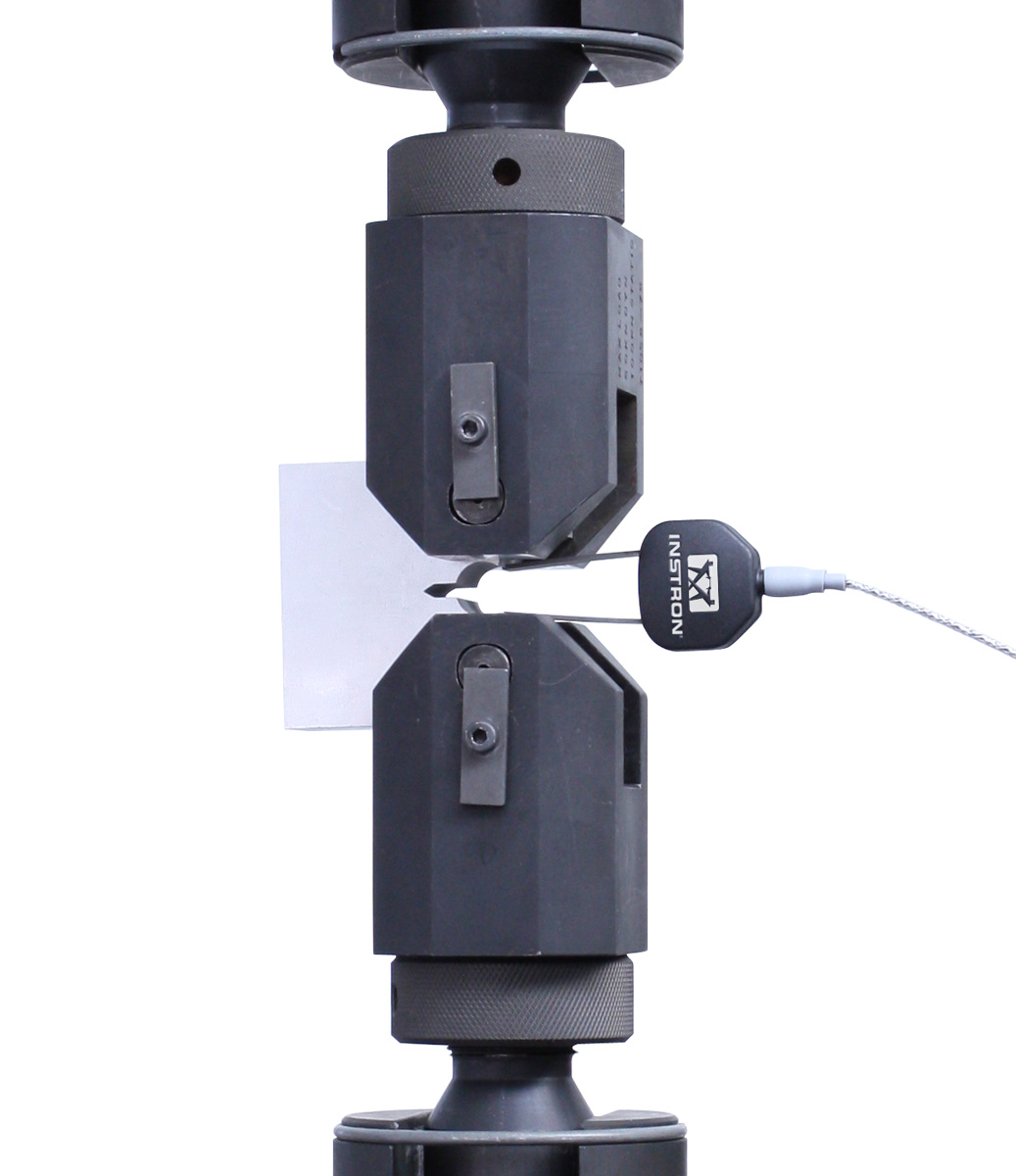
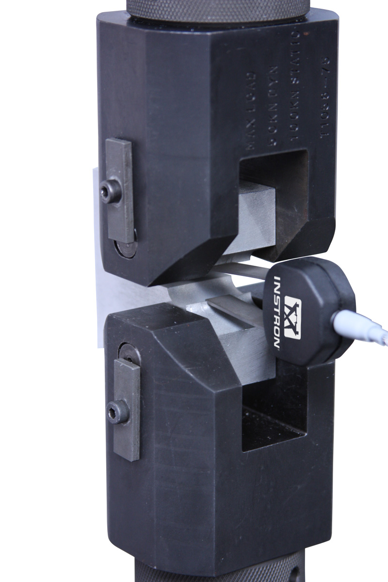
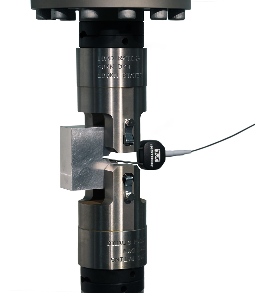
| 标距长度 | 最大行程 | 目录编号 |
| 5 mm(0.20 in) | 2 mm(0.08 in) | 2670-130 |
| 10 mm(0.39 in) | 4 mm(0.16 in) | 2670-132 |
Instron 的食品测试工装适用于多种行业标准测试方法,包括压缩、穿刺、剪切和挤压测试。其提供的多种底座、探头、剪切工装、挤压工装及弯曲工装,适用于研发、质量保证和过程控制测试。Instron 食品测试工装采用耐腐蚀且耐用的材料设计。所有工装均可安装在滴水盘中,以便在评估潮湿、多汁或易碎裂食品的质地时,保持测试区域的清洁。
| 产品名称 | 上部连接件 | 下部连接件 | 目录编号 |
|---|---|---|---|
| 三爪卡盘 | 6 mm 夹销(Om 型) | “仅上部” | 2830-036 |
| 球头探针,5 件套 | 需要三爪卡盘 2830-036 | 需要滴水盘 S5400A 和支撑架 S4472A | S5410A |
| 压缩工装,2580 mm(4 in)面积 | 6 mm 销钉(Om 型) | 需要合适的下底座或支撑板 | S5402A |
| 平剪刀片 | 6 mm 销钉(Om 型) | 需要 S5406A 或 S5401A | S5409A |
| 食品测试工装滴水盘 | 需要食品测试工装 | 0.5 in 销钉(Dm 型) | S5400A |
| 食品夹具装置支撑机架 | 需要食品测试工装 | 滴水盘 S5400A | S4427A |
| 穿刺探头套件 | 三爪卡盘 | “仅上部” | 2830-005 |
| 穿刺探头套件,Magness-Taylor | 三爪卡盘 | “仅上部” | 2830-015 |
| 试样支撑板组 | 需要可选配的食品探头 | 需要滴水盘 S5400A 和支撑架 S4472A | S5401A |
织物环扣夹具用于宽幅或窄幅弹性织物的拉伸及伸长率测试。该测试适用于多种类型的材料或材料组合,并在恒定伸长率下进行。 这两项测试程序 - 在特定伸长率下的环扣拉力测试和在特定环张力下的伸长率测试,要求对试样进行 3 个循环的测试,使其达到规定点后再回归至零值,具体操作如 ASTM D 4964 标准中所述。

| 产品名称 | 目录编号 |
|---|---|
| 织物环扣夹具 | 2717-080 |
试样的正确制备是实现材料准确表征的关键环节。适当的样品制备及充分的缺口加工将影响最终测试结果,从而在最终产品性能中产生可靠的测试结果。这点可通过多种样品制备技术实现,这些技术均符合 ISO 和 ASTM 等主要国际标准的要求。Instron 提供种类丰富的缺口处理、铣削和冲压机器,专为制备从厚到薄、从软到硬的样品而设计。
有关 可选型号 的完整概述,请参阅此文档。
样品制备设备有手动和自动两种设计,能够实现样品制备操作的快速便捷处理,确保获得最准确的结果并提高测试效率。
塑料、橡胶、弹性体、增强塑料材料、薄膜和各材料的薄片
| 产品名称 | 目录编号 |
|---|---|
| CEAST 样品制备冲压机 |
C-6051-000, C-6054-000 |
| CEAST 样品制备缺口机 |
c-6897-000, c-6898-000, c-6899-000 |
| 产品名称 | 目录编号 |
|---|---|
| 用于电液伺服疲劳试验系统的液压夹具控制器 | 2718-111 |
| 产品名称 | 目录编号 |
|---|---|
| 机架支撑座/ 带延伸的底座 | 2910-064 |
| 重型支撑台 | 2910-056 |
| ElectroPuls 试验系统的高刚度支撑座 | 1300-311 和 1300-315 |
卡式夹头夹具通过螺纹连接或螺栓固定到 MT 系列机架的输出轴和 / 或扭矩传感器上。
卡式夹头夹具采用分体式夹头设计,手动拧紧时可对试样施加几乎均匀的夹持力。卡式夹头夹具可夹持的试样直径范围比卡盘式(W-MT01系列)更小,但能承受更高的扭矩。
卡式夹头夹具分为大小两种规格,可夹持多种直径的试样。此外还配备了转接头,用于将卡夹式夹头夹具安装到 MT 系列试验系统的机架上。
| 产品名称 | 目录编号 |
|---|---|
| 大型卡式夹头夹具,试样直径范围 6.3 - 14.25 mm(0.25 in - 0.5625 in) | W-MT02-B |
| 小型卡式夹头夹具,试样直径范围 0.8 - 6.3 mm(0.03125 - 0.25 in) | W-MT02 |
Instron 静态载荷传感器专为我们的 6800 系列、3400 系列、5900 系列和 3300 系列的材料试验系统配套使用而设计。其载荷范围从 2.5 N 到 600 kN 不等,静态载荷传感器适用于多种测试应用,包括拉伸、压缩、循环以及反向应力测试。
紧固件工装可与垫圈、短螺栓连接件和螺母保证载荷组件相配合,便于您对内外螺纹的紧固件进行静态拉伸试验。根据 ASTM F606 的要求,紧固件支架套件能够进行轴向和楔负载拉力试验、拉伸试验和螺母保证载荷试验。


| 供应型号 | ||||
| 描述 | 额定载荷 | 最大试样直径 | 适合的螺纹尺寸 | 目录编号 |
| A 系列紧固件工装,Dm 型 | 100 kN | M12 | 上下接头:Dm 型 | W-5155M-A |
| A 系列紧固件工装 | 150 kN | M12 | M36(R4 型)母接头 | W-5155-A |
| B 系列紧固件工装 | 600 kN | M24 | M48(II RH 型)母接头 | W-5155-B |
| C 系列紧固件工装 | 1000 kN | M72 | M72(IIA RH 型)母接头 | W-5155-C |
| D 系列紧固件工装 | 1500 kN | M48 | M72(IIA RH 型)母接头 | W-5155-D |

| 供应型号 | |||
| 描述 | 兼容的系列工装 | 试样直径 | 目录编号 |
| 普通平垫圈 | A 系列 B 系列 C 系列 D 系列 |
0 - 12 毫米 0 - 24 毫米 0 - 36 毫米 6 - 48 毫米 |
W-5120-A W-5120-B W-5120-C W-5120-D |
| 10° 平楔垫圈 | A 系列 B 系列 C 系列 D 系列 |
0 - 12 毫米 0 - 24 毫米 0 - 36 毫米 0 - 48 毫米 |
W-5121-A W-5121-B W-5121-C W-5121-D |
| 6° 平楔垫圈 | A 系列 B 系列 C 系列 D 系列 |
0 - 12 毫米 0 - 24 毫米 0 - 36 毫米 0 - 48 毫米 |
W-5122-A W-5122-B W-5122-C W-5122-D |
| 4° 平楔垫圈 | A 系列 B 系列 C 系列 D 系列 |
0 - 12 毫米 0 - 24 毫米 0 - 36 毫米 0 - 48 毫米 |
W-5123-A W-5123-B W-5123-C W-5123-D |
| 埋头平垫圈可测试的角度为 60° | A 系列 B 系列 C 系列 |
0 - 12 毫米 0 - 24 毫米 0 - 36 毫米 |
W-5139-A W-5139-B W-5139-C |
| 埋头平垫圈可测试的角度为 82° | A 系列 B 系列 C 系列 |
0 - 12 毫米 0 - 24 毫米 0 - 36 毫米 |
W-5138-A W-5138-B W-5138-C |
| 埋头平垫圈可测试的角度为 100° | A 系列 B 系列 C 系列 |
0 - 12 毫米 0 - 24 毫米 0 - 36 毫米 |
W-5137-A W-5137-B W-5137-C |
| 螺纹平垫圈 | A 系列 B 系列 C 系列 D 系列 |
0 - 12 毫米 0 - 24 毫米 0 - 36 毫米 0 - 48 毫米 |
W-5144-A W-5144-B W-5144-C W-5144-D |

| 供应型号 | |||
| 描述 | 兼容的系列工装 | 试样直径 | 目录编号 |
| 顶帽连接件 | A 系列 B 系列 C 系列 D 系列 |
0 - 6 毫米 0 - 12 毫米 0 - 18 毫米 6 - 24 毫米 |
W-5131-A W-5131-B W-5131-C W-5131-D |
| 哑铃式连接件 | A 系列 B 系列 C 系列 D 系列 |
6 - 12 毫米 12 - 24 毫米 18 - 36 毫米 24 - 48 毫米 |
W-5132-A W-5132-B W-5132-C W-5132-D |

| 供应型号 | ||
| 兼容的系列工装 | 供应的螺纹尺寸范围 | 目录编号 |
| A 系列 | M3 至 M12 | W-5133-A |
| B 系列 | M3 至 M24 | W-5133-B |
| C 系列 | M3 至 M36 | W-5133-C |
| D 系列 | M3 至 M45 | W-5133-D |

| 供应型号 | |
| 描述 | 目录编号 |
| 用于连接 B 系列至 C 系列或 D 系列紧固件工装的适配器 | W-5119-B |
剪切工装旨在测试紧固件承受横向施加到紧固件杆上的载荷的能力。单剪工装可用于剪切拉力试验。双剪工装可用于剪切压缩试验。
适用于疲劳试验系统
我们的标准高温炉和加载链附件,适用于万能试验系统,可在高达 1200°C 空气中运行试验。 我们的工程解决方案团队还能够开发满足更高温度要求和其他高温炉尺寸的解决方案。

2742-205 气动疲劳楔形夹具专为 ElectroPuls® 试验系统而设计,适用于各种试样和材料的拉伸、压缩和反向应力试验。夹具直接通过机器手柄进行气动操作,前开式设计便于试样插入、定位和夹紧。
工作原理 这些夹具采用单作用楔形作用原理,设计用于在不施加压力的情况下夹持试样,从而避免试样发生屈曲。夹具主体的回缩运动有助于减少在夹持试样时产生的压力。
前开式设计允许快速轻松地更换试样和夹面。夹面可优化夹持性能,锯齿夹面旨在最大限度地减少对试样表面破坏。
应用范围
球型底座压盘专为表面不完全平行的压缩试样设计。在施加小预载荷时,球型底座压盘可自动对中试样顶部,与机器加载链相比,对中角度可达 4°。部分型号的球型底座与压盘为一体式结构;其他型号则可通过加装球形底座,将(普通)压盘转换为球形底座压盘。
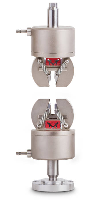
2742-103 气动疲劳楔形夹具专为 ElectroPuls® 试验系统而设计,适用于对各种试样和材料进行拉伸、压缩和反向应力试验。夹具通过机器手柄直接进行气动操作,前开式设计便于试样插入、定位和夹紧。
工作原理 工作原理这些夹具采用单作用楔形作用原理,设计用于在不施加压缩载荷的情况下夹持试样,以避免试样发生屈曲。夹具体的回缩运动有助于减少在夹持试样时产生的压力。
前开式设计允许快速轻松更换试样和夹面。夹面优化了夹持性能,而锯齿面旨在最大限度地减少对试样表面的破坏。
应用范围
Designed as an integral part of the testing platform, in-head wedge grip jaws fit directly into the crosshead pocket of the frame and provide a grip that is adaptable to a variety of testing applications. These jaw faces are made from rugged heat-treated steel designed for durability and minimal maintenance, and are ideal for testing a variety flat, round, and cable specimens in compliance with ASTM E8. The teeth of the jaws are also hardened, and different tooth options increase the application range: a coarse tooth pattern is best for softer materials and higher loads, whereas a finer tooth pattern is best for harder materials. The wedge design causes the gripping force to increase as more tension force is applied. This ensures a secure gripping action with minimal slippage throughout the range of the test.
Filler plates are provided with the purchase of testing frames and allow a variety of specimen thicknesses to be tested. The filler plates adjust the opening of wedge grip jaws by changing the width of the crosshead pocket. All plates should be used for the thinnest specimens and no filler should be used for the thickest specimens.
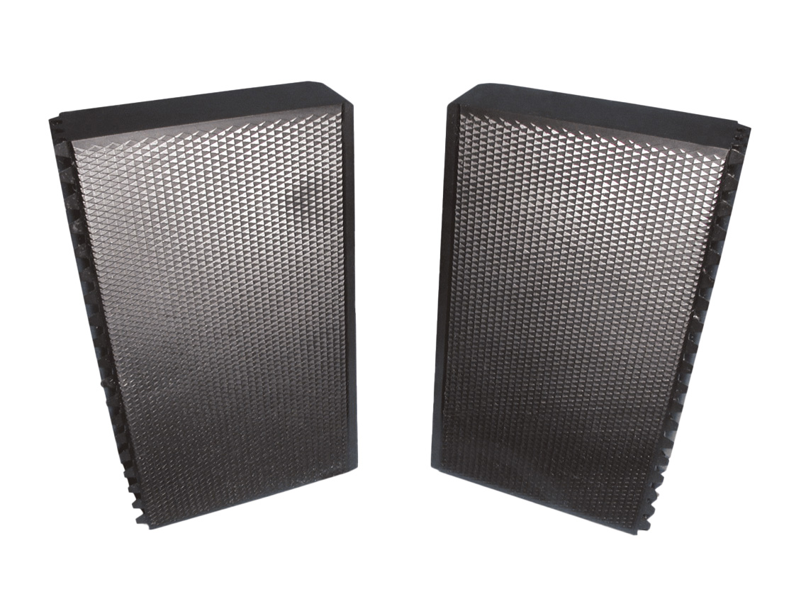
Flat wedge grip jaw faces are ideal for testing a variety of hard, flat specimens. Specimen sizes can also be varied in width, due to the variety of available grips.
| Available Models | ||||||
| Item Description | Force Capacity | Max Specimen Width | Max Specimen Thickness | Tooth Profile | Teeth Per Inch | Catalog No. |
| Jaw Faces | 300 kN | 50 mm | 25 mm | Horizonal | 16 | W-1214 |
| Jaw Faces | 300 kN | 63 mm | 35 mm | Diamond | 8 | W-1258 |
| Jaw Faces | 300 kN | 63 mm | 35 mm | Diamond | 16 | W-1259 |
| Jaw Faces | 600 kN | 70 mm | 45 mm | Horizonal | 8 | W-1408 |
| Jaw Faces | 600 kN | 70 mm | 45 mm | Diamond | 8 | W-1480-A |
| Jaw Faces | 600 kN | 70 mm | 45 mm | Horizonal | 16 | W-1409 |
| Jaw Faces | 600 kN | 70 mm | 45 mm | Diamond | 16 | W-1409-A |
| Jaw Faces | 1000 kN | 82mm | 50 mm | Diamond | 8 | W-1559 |
| Jaw Faces | 1000 kN | 82 mm | 50 mm | Diamond | 16 | W-1560 |
| Jaw Faces | 1500 kN | 90 mm | 76 mm | Diamond | 8 | W-1660 |
| Jaw Faces | 2000 kN | 100 mm | 76 mm | Diamond | 8 | W-1761 |
| Jaw Faces | 3000 kN | 150 mm | 105 mm | Diamond | 8 | W-1911 |
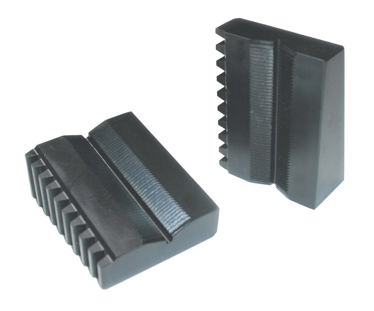
Vee wedge grip jaw faces are ideal for testing a variety of round specimens. Most of the offered jaw faces can also be produced using through-hardened tool steel, which is suitable for re-bar applications. The variety of available jaws also allows variability in the range of specimen diameters. This versatility is due to the different depths and angles of the vee notch in the jaws available, depending on the specific dimensions of the specimen being tested.
| Available Models | |||||
| Item Description | Force Capacity | Specimen Diameter | Tooth Profile | Teeth Per Inch | Catalog No. |
| Jaw Faces | 300 kN | 5.0 - 13.0 mm | Horizonal | 16 | W-1215-A |
| Jaw Faces | 300 kN | 12.0 - 32.0 mm | Horizonal | 16 | W-1215 |
| Jaw Faces | 300 kN | 12.7 - 40.0 mm | Horizonal | 10 | W-1260 |
| Jaw Faces | 300 kN | 12.7 - 40.0 mm | Horizonal | 16 | W-1261 |
| Jaw Faces | 600 kN | 7.0 - 25.0 mm | Horizonal | 16 | W-1410-A |
| Jaw Faces | 600 kN | 12.7 - 57.0 mm | Horizonal | 10 | W-1410 |
| Jaw Faces | 600 kN | 12.7 - 57.0 mm | Horizonal | 16 | W-1411 |
| Jaw Faces | 1000 kN | 6.0 - 12.7 mm | Horizonal | 16 | W-1563-A |
| Jaw Faces | 1000 kN | 12.7 - 57.0 mm | Horizonal | 10 | W-1561 |
| Jaw Faces | 1000 kN | 12.7 - 57.0 mm | Horizonal | 16 | W-1563 |
| Jaw Faces | 1000 kN | 45.0 - 85.0 mm | Horizonal | 10 | W-1562 |
| Jaw Faces | 1500 kN | 10.0 - 63.0 mm | Horizonal | 8 | W-1669-A |
| Jaw Faces | 1500 kN | 12.7 - 82.0 mm | Horizonal | 10 | W-1662 |
| Jaw Faces | 2000 kN | 10.0 - 63.0 mm | Horizonal | 8 | W-1669-B |
| Jaw Faces | 2000 kN | 32.0 - 95.0 mm | Horizonal | 10 | W-1763 |
| Jaw Faces | 3000 kN | 10.0 - 60.0 mm | Diamond/Horizonal Grip body range from 25 mm (#8) to 60 mm (#18), diamond cut, 10 teeth per inch Grip inserts range from 10 mm (#3) to 25 mm (#8), horizontal cut 10 teeth per inch |
10 | W-1916 |
| Jaw Faces | 3000 kN | 35.0 - 125.0 mm | Horizonal | 10 | W-1912 |

Cable jaw face inserts are ideal for testing seven stranded cable specimens. Cable grip jaws are only available for load frames with a capacity of 600 kN (135,000 lbs) or greater.
| Available Models | |||
| Item Description | Force Capacity | Specimen Diameter | Catalog No. |
| Insert Holders | 2000 kN | W-1538 | |
| Inserts | 2000 kN | 11.11 mm | W-1538-B |
| Inserts | 2000 kN | 12.70 mm | W-1538-C |
| Inserts | 2000 kN | 12.90 mm | W-1538-F |
| Inserts | 2000 kN | 13.20 mm | W-1538-G |
| Inserts | 2000 kN | 15.24 mm | W-1538-H |
| Inserts | 2000 kN | 15.88 mm | W-1538-D |
| Inserts | 2000 kN | 19.05 mm | W-1538-E |

2742-206 手动疲劳楔形夹具专为 ElectroPuls® 试验系统而设计,适用于对各种试样和材料进行拉伸、压缩、扭转和反向应力试验。夹具为手动操作,前开式设计便于试样插入、定位和夹紧。
工作原理 轴承辅助楔形的设计使您无需工具就轻松拧紧夹具。如有必要,也可以使用撬杆或扳手来完成。在这两种情况下,此调整均不会改变夹面相对于试样的垂直位置。
Instron® 的这种夹具主体移动,而非夹面移动的设计,可以预设试样夹持的确切位置,保证标距一致且不施加任何可能导致试样屈曲的压力。前开式设计允许快速轻松地更换夹面。锯齿夹面可实现最佳夹持性能,锯齿设计可最大限度地减少对试样表面的破坏。拉杆也适用于非环境温度下的试验。
应用范围
操作原理
Electropuls拉杆套件包含4个不同长度的拉杆,适用于疲劳、拉伸、压缩和扭转试验。当结合3119-605试验箱在新ElectroPuls试验机(除了E1000)上配置3119-605温度箱使用时,拉杆套件可优化兼容配件,实现最大操作范围。

如需了解更多信息,请下载资料
访问ElectroPuls网页
Compression deflectometers, or linear variable differential transformer (LVDT) displacement transducers are instruments that measure the displacement of the load frames. These measuring devices feature an LVDT as the active element and can be used on electromechanical and hydraulic testing systems.
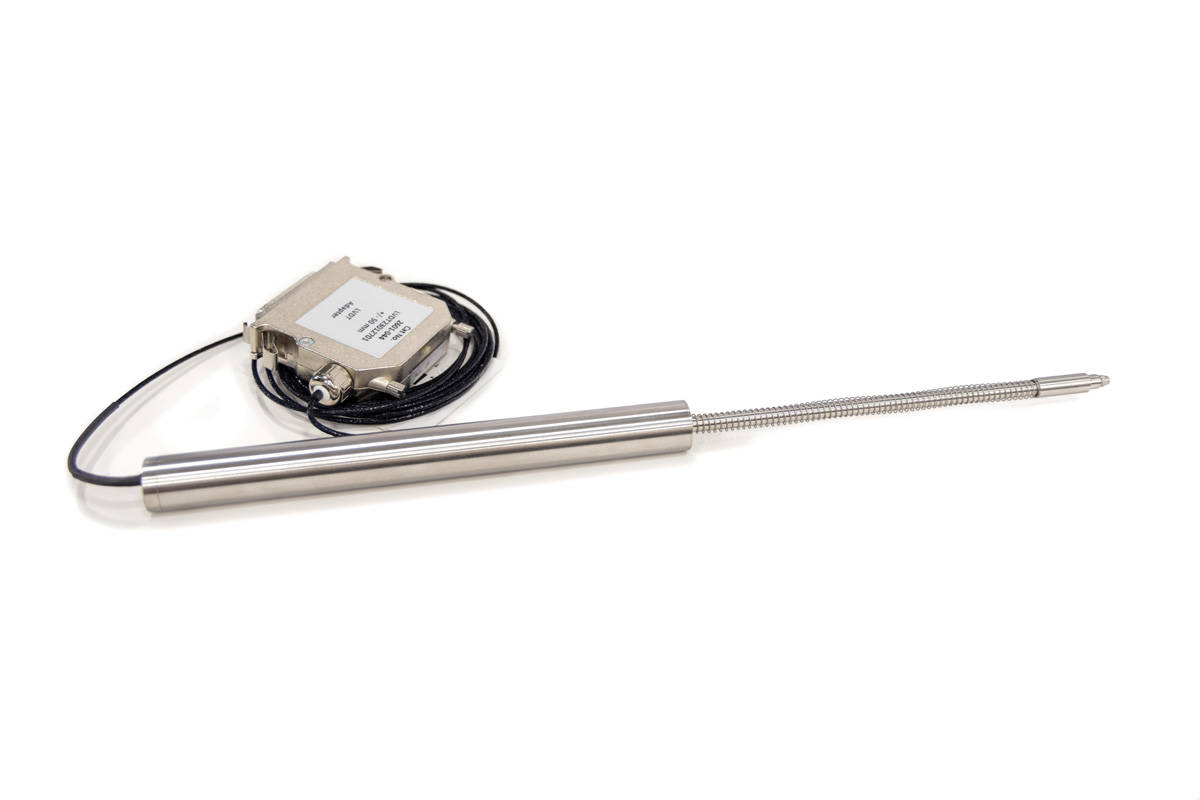
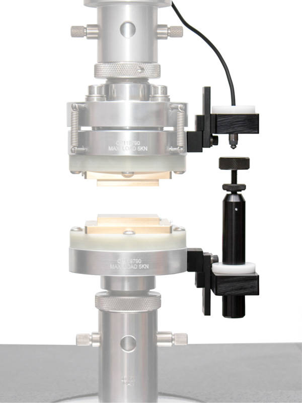
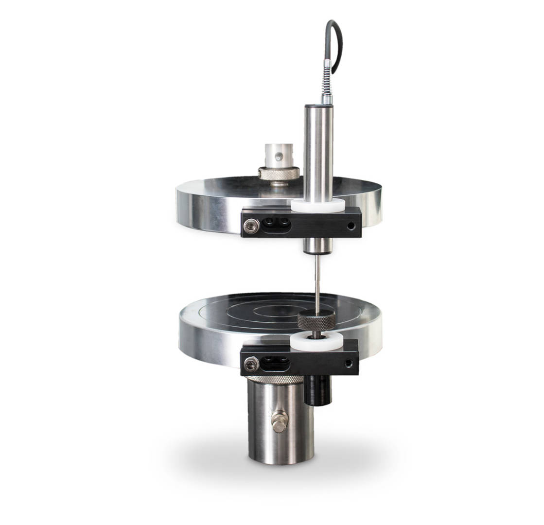
The 2601 Series Linear Variable Differential Transformer (LVDT) displacement transducers are measuring devices that measure the displacement of the load frames. They are best suited for situations where measuring strain on the specimen is difficult or impossible and can be used on compression and tensile tests. LVDT’s are preferred to crosshead extension readings because they eliminate errors due to frame and fixture compliance. They feature an LVDT as the active element and are designed for use on both electromechanical and hydraulic testing systems.
| Available Models | |||
| Measuring Range | Standard Temperature Range | Catalog No. | |
| +/- 0.5 mm (+/- 0.02 in) | -10 °C to +80 °C (+14 °F to +176 °F) | 2601-041 | |
| +/- 2.5 mm (+/- 0.1 in) | -10 °C to +80 °C (+14 °F to +176 °F) | 2601-042 | |
| +/- 15 mm (+/- 0.6 in) | -40 °C to +100 °C (-40 °F to +212 °F) | 2601-043 | |
| +/- 50 mm (+/- 2 in) | -40 °C to +100 °C (-40 °F to +212 °F) | 2601-044 | |
| +/- 100 mm (+/- 4 in) | -40 °C to +100 °C (-40 °F to +212 °F) | 2601-045 | |
| Accessories | |||
| Description | Catalog No. | ||
| Magnetic Base LVDT Holder | 2601-069 | ||
| LVDT Platen Displacement Fixture | 2601-071 | ||
| Precision Micrometer, 0-50 mm (2 in) for Manual Calibration of LVDTs | 2601-072 | ||
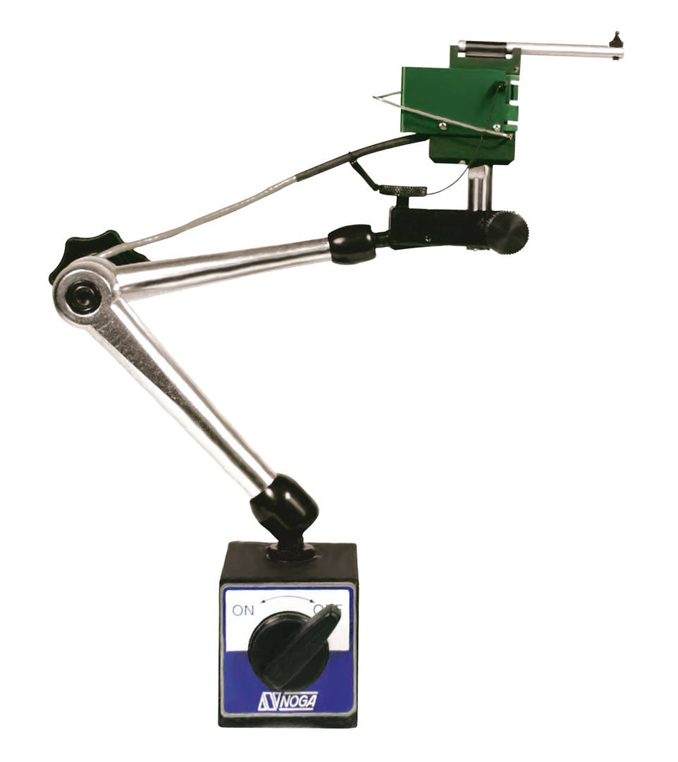
The E-Series strain displacement deflectometers are often used for measuring deflection in 3 and 4 point bend tests, compression tests, and a variety of general test deflection measurements. The unit includes a magnetic base for easy mounting and a standard 25 pin connector.
| Available Models | |||
| Travel | Standard Temperature Range | Catalog No. | |
| 0.15 in | -40°F to 210°F (-40°C to 100°C) | W-E401-A | |
| 1.0 in | -40°F to 210°F (-40°C to 100°C) | W-E401-D | |
| 2.0 in | -40°F to 210°F (-40°C to 100°C) | W-E401-J | |
| 6 mm | -40°F to 210°F (-40°C to 100°C) | W-E401-F | |
| 12 mm | -40°F to 210°F (-40°C to 100°C) | W-E401-G | |
| 25 mm | -40°F to 210°F (-40°C to 100°C) | W-E401-H | |
| Accessories | |||
| Description | Catalog No. | ||
| Magnetic Base LVDT Holder | 2601-069 | ||
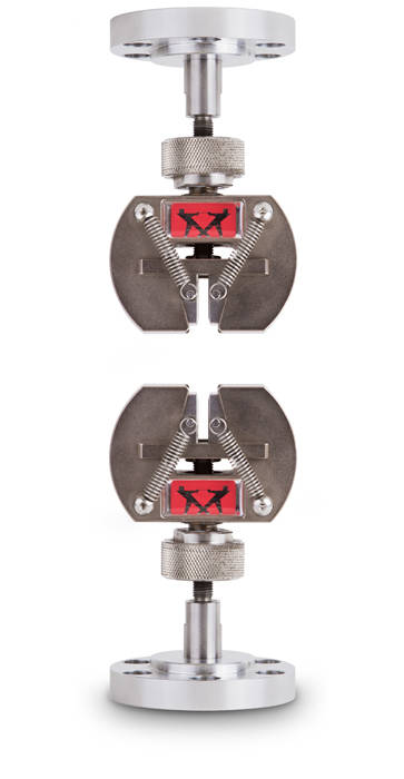
2742-102 手动疲劳楔形夹具专为 ElectroPuls® 试验系统而设计,适用于各种试样和材料的拉伸、压缩和反向应力试验。夹具为手动操作,前开式设计便于试样插入、定位和夹紧。
工作原理 夹具的楔形作用原理使其可以用手(或用带有额外夹持力的扳手)轻松地夹紧试样,同时不改变夹面相对于试样的表面的垂直位置。Instron® 的这种夹具体移动而非夹面移动的设计,可以预先准确定位试样的夹持点,保证试样标距一致且不施加可能导致试样屈曲的压力。
前开式设计便于快速更换夹面。锯齿状的夹面可实现最佳夹持性能,锯齿设计旨在最大限度减少对试样表面的破坏。
提供适用于 ElectroPuls 设备和其他系统的附件套件。
应用范围
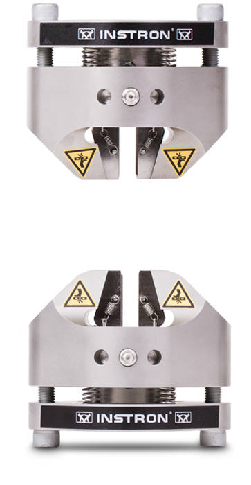
2742-315机械楔形夹具专为ElectroPuls® E10000线性扭转系统而设计,适用于各种试样和材料的拉伸、压缩、反向应力和扭转试验。夹具为机械操作,前开式设计便于样品插入、定位和夹紧。
操作原理这些夹具的仅楔形夹体作用原理旨在不施加压缩载荷的情况下夹紧试样,否则可能导致试样屈曲。
夹体的缩回运动有助于减少通常在夹紧试样时产生的压缩载荷。
前开式设计允许快速轻松地更换夹面。夹面可优化夹持性能,锯齿夹面旨在最大限度地减少对试样表面的损伤。
应用范围
可选择气动控制装置、脚踏开关和分配套件,从而方便夹具闭合并提高使用气动夹具时的工作效率,包括使用气动平推拉伸夹具、气动绳线夹具、气动剥离工装等。
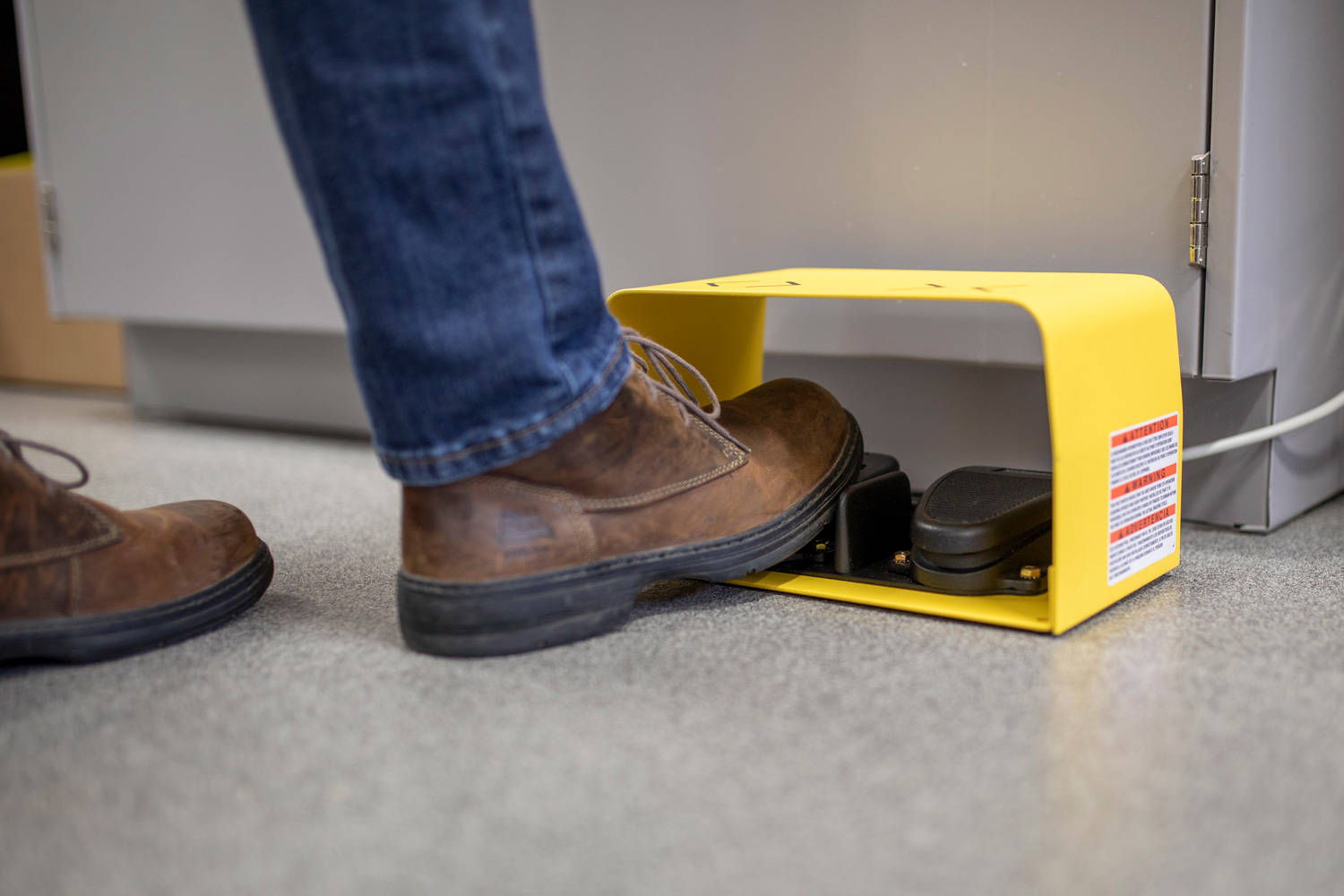

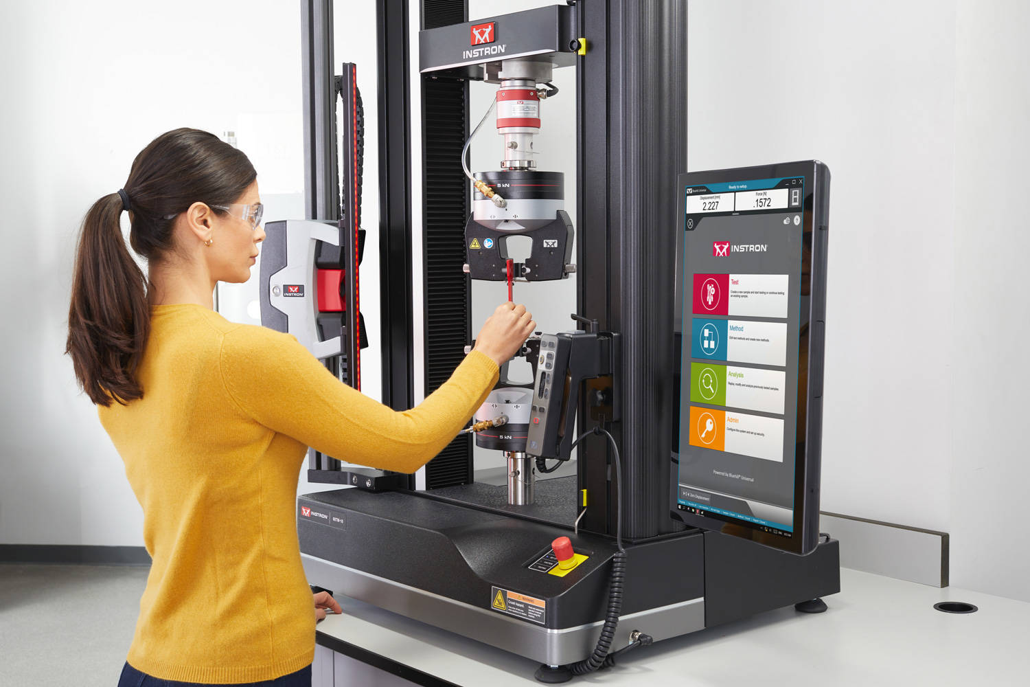
智能气动控制装置是一种系统集成选项,可用于监测和控制向 Instron 气动夹具施加的气压。
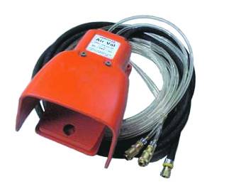
通用气动脚踏开关旨在提供按顺序的夹持动作,使操作员无需手动操作,可以解放双手来对齐夹具中的试样。
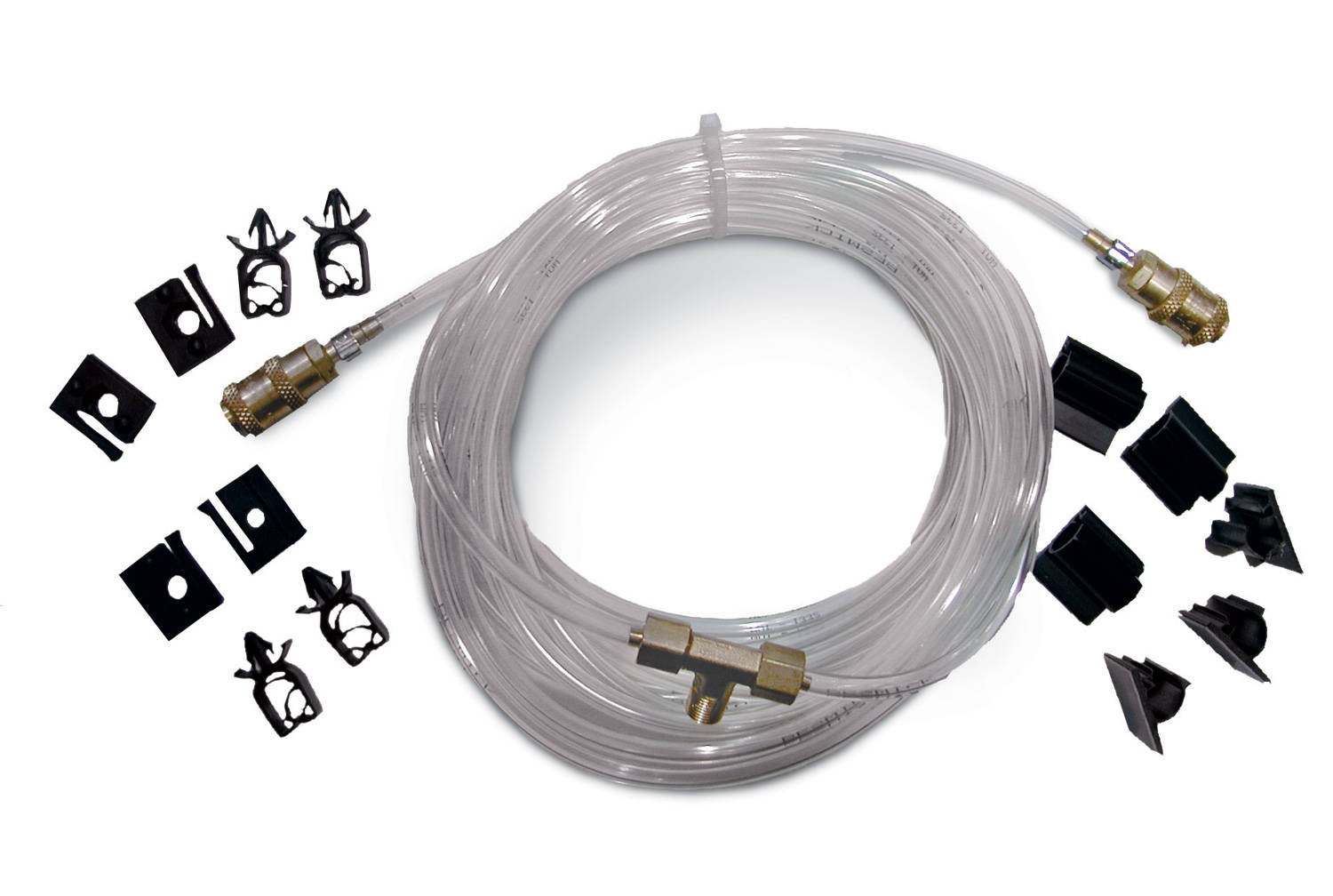
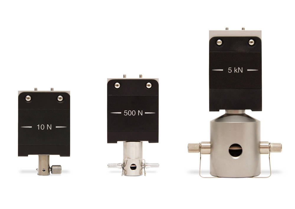
2519 系列载荷传感器专为 3400 和 3300 系列单立柱试验系统设计。其具备自动传感器识别和电子校准功能,使用便捷。这系列载荷传感器内置过载保护功能,在承受高达 150% 载荷时不会损坏,承受 300% 的载荷也不会发生机械故障。此外,即便夹具或工装的皮重达到载荷的 40%,用户仍可对其进自重归零,同时仍保持规定的精度。
Instron 所有载荷传感器均经过单独的温度补偿,并使用可溯源至国际标准的校准设备进行了精度和可重复性测试,测量的不确定度不超过传感器允许误差的三分之一。
Instron 2519 系列载荷传感器是一种精密力传感器,由一个完整的应变片电桥组成,该电桥粘贴在刚性强且线性度高的弹性元件上。当弹性元件受到力的作用时,应变片的电阻会发生变化,从而输出与所施加力成比例的信号。
这些载荷传感器适用于拉伸、压缩、循环及反向应力试验。它们的测量范围广泛,能够精确测量低至 1/500 载荷的力,从而减少了更换载荷传感器的需求
| 项目名称 | 载荷范围 | 机械配件 | 目录 # |
|---|---|---|---|
| 10 N 静态载荷传感器 | 0.01 kN 2.2 lbf |
2.5 mm 销钉,带 6 mm 转接头(OOf 型 & Of) |
2519-10N |
| 50 N 静态载荷传感器 | 0.05 kN 11 lbf |
2.5 mm 销钉,带 6 mm 转接头(OOf 型 & Of) |
2519-50N |
| 100 N 静态载荷传感器 | 0.1 kN 22 lbf |
2.5 mm 销钉,带 6 mm 转接头(OOf 型 & Of) |
2519-100N |
| 500 N 静态测载荷传感器 | 0.5 kN 112 lbf |
6.0 mm 销钉(Of 型) |
2519-500N |
| 1 kN 静态载荷传感器 | 1 kN 225 lbf |
6.0 mm 销钉(Of 型) |
2519-1KN |
| 2 kN 静态载荷传感器 | 2 kN 450 lbf |
6.0 mm 销钉(Of 型) |
2519-2KN |
| 5 kN 静态载荷传感器 | 5 kN 1125 lbf |
0.5 in 销钉(Df 型) |
2519-5kN |

2530 系列载荷范围为 5 N 至 100 N 的载荷传感器,可与 6800 系列、3400 系列、5900 系列及 3300 系列万能材料试验系统配套使用。2530 系列载荷范围为 500 N 至 300 kN 的载荷传感器,则适用于 3400 系列和 3300 系列万能材料试验系统。其设计、制造和性能验证均充分考虑了材料测试应用的需求。传感器具备自动识别和电子标定功能,使用便捷。同时,载荷传感器内置过载保护装置,能够承受高达其额定力值 150% 的载荷而不受损,承受 300% 的载荷时也不会发生机械损伤。根据不同型号,载荷传感器允许用户对重量达到其额定力值 10% 或 40% 的夹具或工装进行载荷清零操作,同时仍能保持规定的满量程精度。
所有 Instron 载荷传感器均经过单独的温度补偿处理,并在可追溯至国际标准的标定设备上对其准确性和重复性进行测试,该标定设备的测量误差不超过载荷传感器允许误差的三分之一。
您是否正在寻找 2519 系列载荷传感器?
2519 系列载荷传感器已停产。不过,我们很高兴能提供 2530 系列载荷传感器作为直接替代产品。2530 系列专为在大多数应用场景中无缝替代 2519 系列载荷传感器而设计。
如您需要技术参数、兼容性详细信息或过渡到 2530 系列的帮助,请联系我们。
应用范围
产品
| 产品名称 | 载荷范围 | 接头规格 | 目录编号 |
|---|---|---|---|
| 5 N 静态载荷传感器 | 0.005 kN 1.12 lbf |
带 6 mm 转接头的 2.5 mm 销钉 (OOf & Of 型) |
2530-5N |
| 10 N 静态载荷传感器 | 0.01 kN 2.25 lbf |
带 6 mm 转接头的 2.5 mm 销钉 (OOf & Of 型) |
2530-10N |
| 50 N 静态载荷传感器 | 0.05 kN 11.2 lbf |
带 6 mm 转接头的 2.5 mm 销钉 (OOf & Of 型) |
2530-50N |
| 100 N 静态载荷传感器 | 0.1 kN 22.5 lbf |
带 6 mm 转接头的 2.5 mm 销钉 (OOf & Of 型) |
2530-100N |
| 500 N 静态载荷传感器 | 0.5 kN 112 lbf |
6.0 mm 销钉 (Of 型) |
2530-500N |
| 1 kN 静态载荷传感器 | 1 kN 225 lbf |
6.0 mm 销钉 (Of 型) |
2530-1kN |
| 2 kN 静态载荷传感器 | 2 kN 450 lbf | 6.0 mm 销钉 (Of 型) |
2530-2kN |
| 5 kN 静态载荷传感器 | 5 kN 1125 lbf |
0.5 in 销钉 (Df 型) |
2530-5kN |
| 10 kN 静态载荷传感器 | 10 kN 2250 lbf |
0.5 in 销钉 (Df 型) |
2530-10kN |
| 30 kN 静态载荷传感器 | 30 kN 6750 lbf |
0.5 in 销钉 (Df 型) |
2530-30kN |
| 50 kN 静态载荷传感器 | 50 kN 11250 lbf |
0.5 in 销钉 (Df 型) |
2530-50kN |
| 100 kN 静态载荷传感器 | 100 kN 22500 lbf |
0.5 in 销钉 (Df 型) |
2530-100kN |
| 300 kN 静态载荷传感器 | 300 kN 67500 lbf |
M48 x 2LH (IIF 型),6 个 M20 在 150 PCD 上,6 个 M10 在 100 mm PCD 上 |
2530-300kN |

2742-315 气动楔形夹具专为 ElectroPuls® 10000 系统设计,适用于对各种样品和材料进行拉伸、压缩、扭转和反向应力测试。夹具由机器手柄直接气动操作,开放式设计便于试样插入、定位和夹紧。
工作原理 这些夹具采用单作用楔形作用原理,设计用于在不施加压力的情况下夹持试样,从而避免试样发生屈曲。夹具主体的回缩运动有助于减少在夹持试样时产生的压力。
前开式设计允许快速轻松更换试样和夹面。夹面优化了夹持性能,而锯齿夹面旨在最大限度地减少对试样表面的破坏。
应用范围

2580 系列传感载荷器专为 6800 和 5900 系列试验系统设计,性能卓越,能够测量低至 1/1000 载荷的力值,且精度可达读数的 0.5%。该系列载荷传感器可承受高达 150% 的载荷而不损坏,承受 300% 的载荷也不会发生机械故障。其具备自动传感器识别和电子标定功能,使用便捷。此外,操作人员可以在满量程的10%以内执行载荷清零操作,同时仍能保持规定的满量程精度。 Instron 所有载荷传感器均经过单独的温度补偿,并使用可溯源至国际标准的标定设备进行了精度和可重复性测试,测量的误差不超过传感器允许误差的三分之一。
Instron 2580 系列载荷传感器是高精度力传感器,其内部包含一个完整的应变片电桥,该电桥粘贴在超高刚度的弹性元件上。当该元件受到力的作用时,应变片的电阻会发生变化,从而产生与所施加力成比例的输出信号。弹性元件采用双剪切设计,这确保了在整个测试过程中具有出色的对中性,并且即使在测试大型试样时,也能有效抵抗偏离载荷。
2580 系列载荷传感器上的环形和销钉设计能够确保您每次使用时,载荷传感器都能正确居中并安装在相同位置。
调平螺栓组件适用于 10 kN、30 kN 和 50 kN 的载荷传感器,它是一种有效的装置,能在更易控制的扭矩范围内将载荷传感器安全固定到试验系统上。
应用范围
产品
| 产品名称 | 载荷范围 | 机械配件 | 目录编号 |
|---|---|---|---|
| 500 N 静态载荷传感器 | 0.5 kN |
6.0 mm 销钉(Type Of) |
2580-500N |
| 1 kN 静态载荷传感器 | 1 kN |
6.0 mm 销钉(Type Of) |
2580-1KN |
| 2 kN 静态载荷传感器 | 2 kN |
6.0 mm 销钉(Type Of) |
2580-2KN |
| 5 kN 静态测载荷传感器 | 5 kN |
0.5 in 销钉(类型 Df) |
2580-5KN |
| 10 kN 静态载荷传感器 | 10 kN |
0.5 in 销钉(Type Df) |
2580-10KN |
| 30 kN 静态载荷传感器 | 30 kN |
0.5 in 销钉(Type Df) |
2580-30KN |
| 50 kN 静态载荷传感器 | 50 kN |
0.5 in 销钉(Type Df |
2580-50KN |
| 100 kN 静态载荷传感器 | 100 kN |
0.5 in 销钉(Type Df) |
2580-100KN |
| 150 kN 静态测载荷传感器 | 150 kN |
M48 x 2LH(IIF 型),6 个 M20,位于 150 mm PCD 上,6 个 M10,位于 100 mm PCD 上 |
2580-150KN |
| 250 kN 静态载荷传感器 | 250 kN |
M48 x 2LH(IIF 型),6 个 M20,位于 150 mm PCD 上,6 个 M10,位于 100 mm PCD 上 |
2580-250KN |
| 300 kN 静态载荷传感器 | 300 kN |
M48 x 2LH(IIF 型),6 个 M20,位于 150 mm PCD 上,6 个 M10,位于 100 mm PCD 上 |
2580-300KN |
| 400 kN 静态载荷传感器 | 400 kN |
M48 x 2LH(IIF 型),6 个 M20,位于 150 mm PCD 上,6 个 M10,位于 100 mm PCD 上 |
2580-400KN |
| 600 kN 静态载荷传感器 | 600 kN |
M72 x 3LH(IIF 型),6 个 M10,位于 100 mm PCD 上 |
2580-600KN |
T 型槽工作台为 DX 型静态液压万能试验机的压缩空间提供了一种极具通用性的工装固定方式,可用于测试尺寸不规则的试样。将市售的 T 型槽螺母滑入工作台的倒 T 型槽中,然后即可将螺栓、螺柱或螺纹杆拧入螺母内。对于那些在负载作用下可能会从测试空间弹出的试样,T 型槽工作台可起到固定作用。它还能将试样定位在同一位置,以便进行重复测试或产品的批量测试。此外,可在工作台上安装导向件、滑块或挡块并通过螺栓固定,确保每次测试时试样都能精确放置。当测试空间内的工装被移除后,T型槽工作台能够像加载台一样,承受达到系统满载的压缩载荷。
该工作台通过螺栓固定在机架上,其制造尺寸通常能覆盖加载台的整个宽度和深度。根据机架型号的不同,该工作台会使可用压缩空间减少 50 至 75 mm(2 至 3 in)。机架的加载台必须进行钻孔和攻丝处理,以适配 T 型槽工作台。
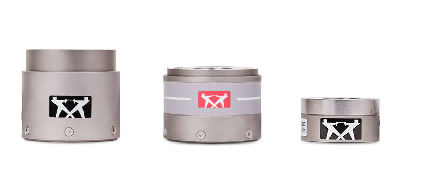
在电液伺服疲劳试验系统上进行测试时,系统元件会受到加速度的影响。因此,除了施加于试样上的力之外,载荷传感器还会读取因其自身运动以及所连接的夹具、工装的质量所产生的惯性。
Dynacell 是全球首款真正意义上的动态载荷传感器,其设计初衷用于测量动态载荷。Dynacell 具有以下优势:
Dynacell 在将速度计置于载荷传感器的核心位置,直接安装在轴心上。此设计消除了因偏心力导致的加速度读数出现误差的风险。
具有以下优势:
Dynacell 的加速度信号调节由 FastTrack 8800 电子设备进行标准化处理,并在系统自动调谐时自动完成设置。这意味着既节省了时间,还减少了操作员可能造成的失误。
对于希望自行操作的用户,他们可以选择开启或关闭该功能,并手动设置校正系数。随后将由此产生的信号从载荷传感器信号中减去,即可得出作用在试样上的真实力值。
应用范围
产品
| 产品名称 | 目录编号 |
|---|---|
| 双轴 Dynacell 动态载荷传感器,±25 kN (±5620 lbf), ±100 Nm (±880 in-lb) | 2527-201 |
| 双轴 Dynacell 动态载荷传感器,±10 kN (±2250 lbf), ±100 Nm (±880 in-lb) | 2527-202 |
| 双轴 Dynacell 动态载荷传感器,±1 kN (±225 lbf), ±25 Nm (±220 in-lb) | 2527-302 |
| 双轴 Dynacell 动态载荷传感器,±5 kN (±1124 lbf), ±25 Nm (±220 in-lb) | 2527-303 |
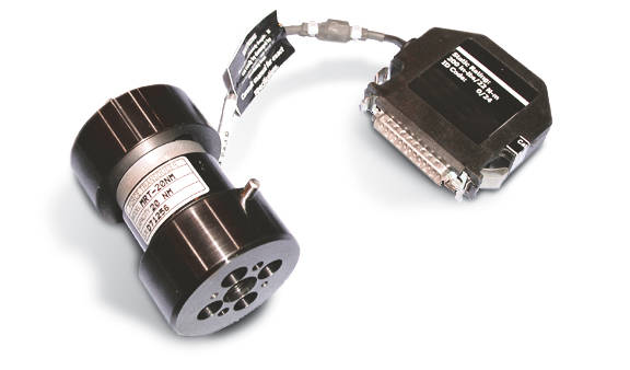
与 55MT 系列扭转试验机配套使用的扭转传感器有多种规格,具体取决于试验机型号。较低载荷的传感器可扩展设备的量程,并增强 55MT 系列试验机的功能。
对于 55MT1,扭转传感器是微型反作用扭矩传感器。这些传感器非常小,具有出色的线性和重复性。所有传感器都使用相同的安装模式,因此夹具的互换性不成问题(夹具的重量可能是 2 in-lb 传感器的因素)。
这些传感器配有集成的安装和过载保护板,用于将主传感器安装在 55MT1 试验机上。这不仅为主传感器提供保护,而且还允许从主传感器到低量程传感器的极快速更换。
对于较大的 55MT2 和 55MT20 试验机,这些传感器是法兰式反作用扭矩传感器。这提供了更高的抗弯矩能力。该传感器具有高扭转刚度和低端灵敏度。
特定试验机的所有传感器都使用标准圆形安装模式,因此传感器使用与主传感器相同的硬件安装到试验机。由于所有现有夹具都以与主传感器相同的方式安装到较低容量的传感器,因此无需额外的适配器。
所有扭转传感器都将旋转运动转换为代表感应扭矩的电信号。当需要测试较小的样品时,可以添加低容量传感器以增加机器的工作范围。
如果被测试样的最大施加扭矩远低于试验机的容量,则添加低量程传感器将提高扭矩测量传感器的分辨率。
在 55MT1 和 55MT2 试验机上安装扭矩传感器仅需要使用内六角扳手,因此更换非常容易。这减少了停机时间并提高了生产率。对于较大的 55MT20,更换传感器时需要带有内六角套筒的扭矩扳手。
应用范围
产品
| 项目名称 | 扭矩容量 | 附件直径 | 目录 # |
|---|---|---|---|
| 扭转力传感器 | 0.225 Nm 2 in-lb |
54.0 mm 2.125 in |
W-5510-T4 |
| 扭转力传感器 | 2.25 Nm 20 in-lb |
54.0 mm 2.125 in |
W-5510-T3 |
| 扭转力传感器 | 22 Nm 200 in-lb |
54.0 mm 2.125 in |
W-5510-T2 |
| 扭转力传感器 | 220 Nm 2,000 in-lb |
101.6 mm 4.00 in |
W-5510-T1 |
应变测量是力学试验的关键组成部分,几乎所有相关的 ASTM 和 ISO 标准都要求进行应变测量。Instron 提供种类繁多的应变测量设备,以满足各种材料和应用的需求。 从简单的粘贴式应变片到最先进的视频引伸计测量法,我们所有的设备均由 Instron 工程师设计并制造,以满足我们自身严格的精度标准。如果您在试验应用中需要创新解决方案,我们的定制工程团队可为您提供量身定制的应变测量方案,以满足您的具体需求。
扭转夹具旨在向试样传递扭转力,通常采用卡盘式或套筒式夹持结构。而轴向扭转夹具则需配合能同时施加扭转载荷与轴向载荷的系统使用。
低速后碰、侧面和柱碰撞模拟的工装,有助于提高开发过程的生产力和效率。
Instron® 是唯一一家自行设计和制造载荷传感器的试验系统制造商。这确保了 Instron 载荷感器满足材料试验系统的独特要求,例如在广泛测量范围内具有高精度、高刚度、抗偏离载荷、精确对中和出色的零点稳定性。这些载荷传感器在 Instron 位于英国 High Wycombe 的制造中心制造。所有 Instron 载荷传感器都经过单独的温度补偿,并在可溯源至国际标准的标定设备上进行精度和可重复性测试,其不确定性不超过载荷传感器所允许误差的三分之一。Instron 的 Massachusetts 总部拥有美国最大的商用静重式试验机,这使得 Instron 载荷传感器通常能够超过大多数材料测试标准要求的精度水平。
Instron® 提供种类多样的拉伸夹具,可满足不同行业与测试应用需求。我们的夹具载荷范围从 1 g 至 2 MN,能适配各类材料,包括线材、绳索、弹性体、塑料、复合材料、金属等。针对特殊应用场景,我们的定制工程团队可按依照您的需求设计专属夹具。Instron 夹具符合全球所有测试标准,设备使用寿命长达数十年,并由我们遍及全球的服务团队提供售后保障。
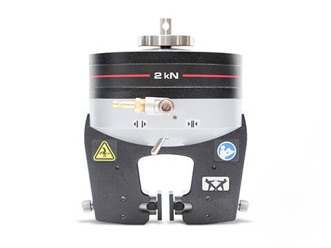
气动平推
拉伸夹具
作为 Instron 最受欢迎的拉伸夹具,超过半数的 Instron 试验系统均配备此款。该夹具操作简便、适用性极强,尤其适用于大批量测试的场景,最大载荷范围可达 10 kN。
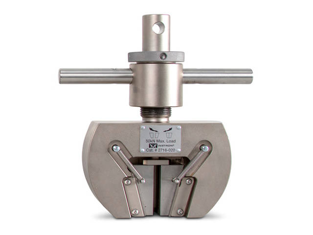
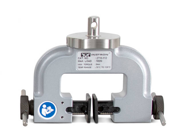
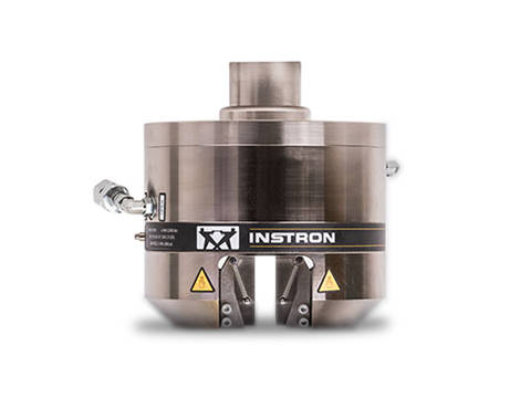
无论您的应用涉及注射器、鲁尔锁、自动注射器、笔式注射器、缝合线、假肢、植入物、医疗包装或个人防护设备,Instron都能提供一系列夹具和附件,用于按照行业标准进行测试。要了解更多关于给药设备和容器、医用耗材和包装、心血管和介入设备、生物材料、整形外科植入物和牙科设备的最新测试应用,请访问我们的生物医学行业页面。
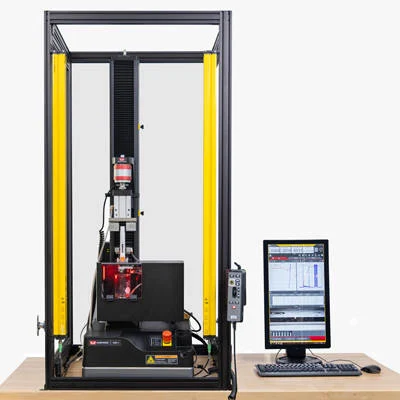

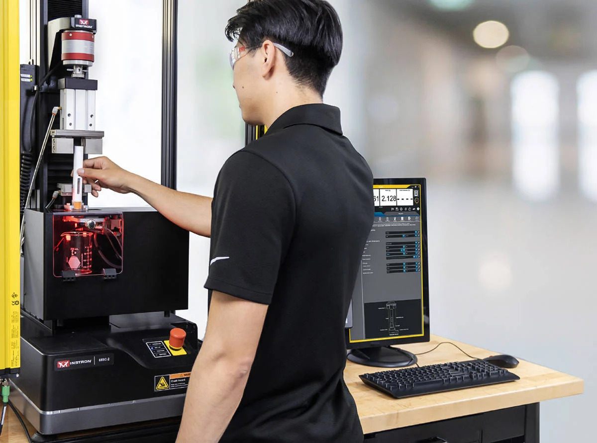
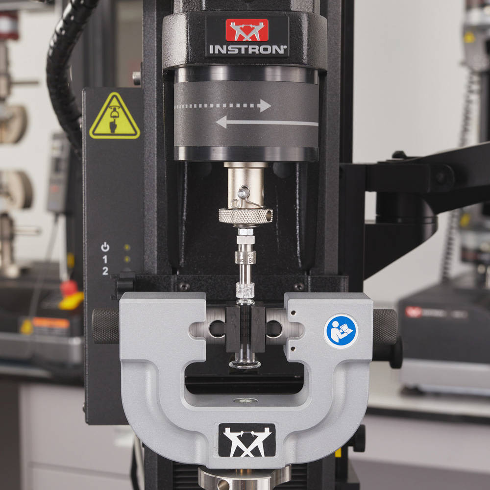
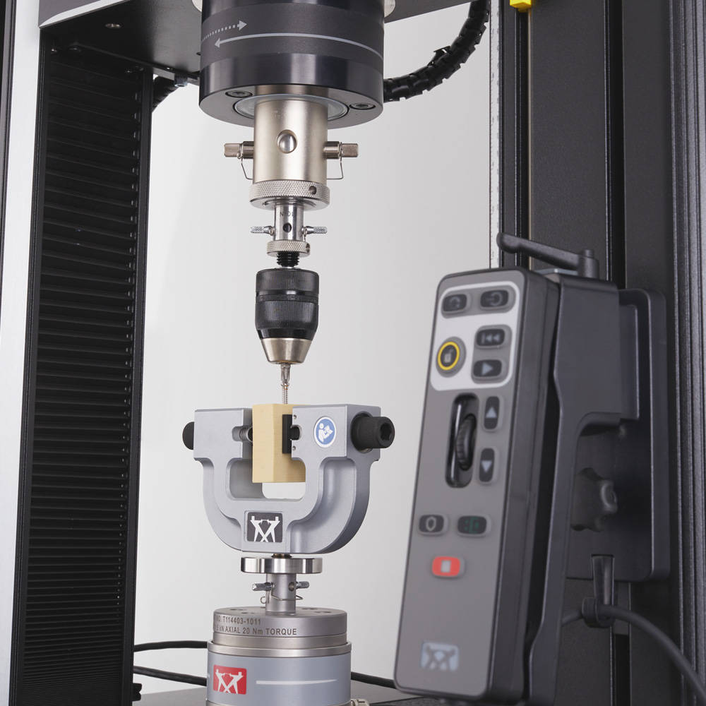
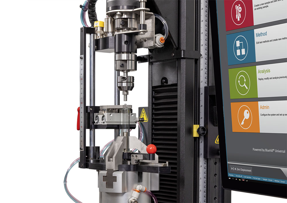
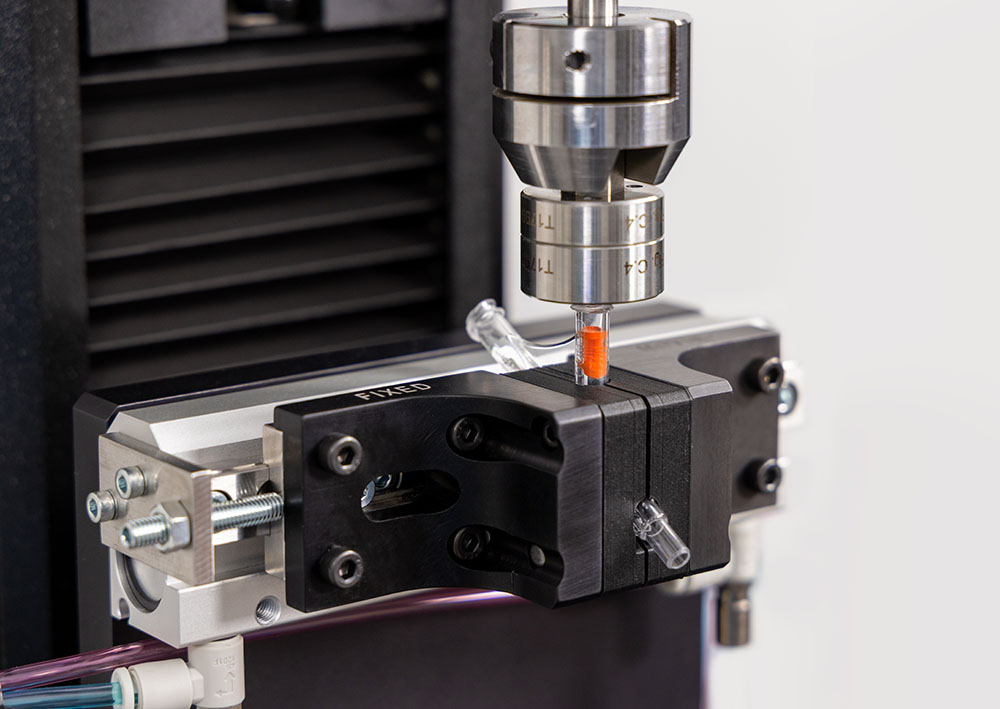
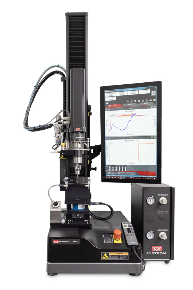
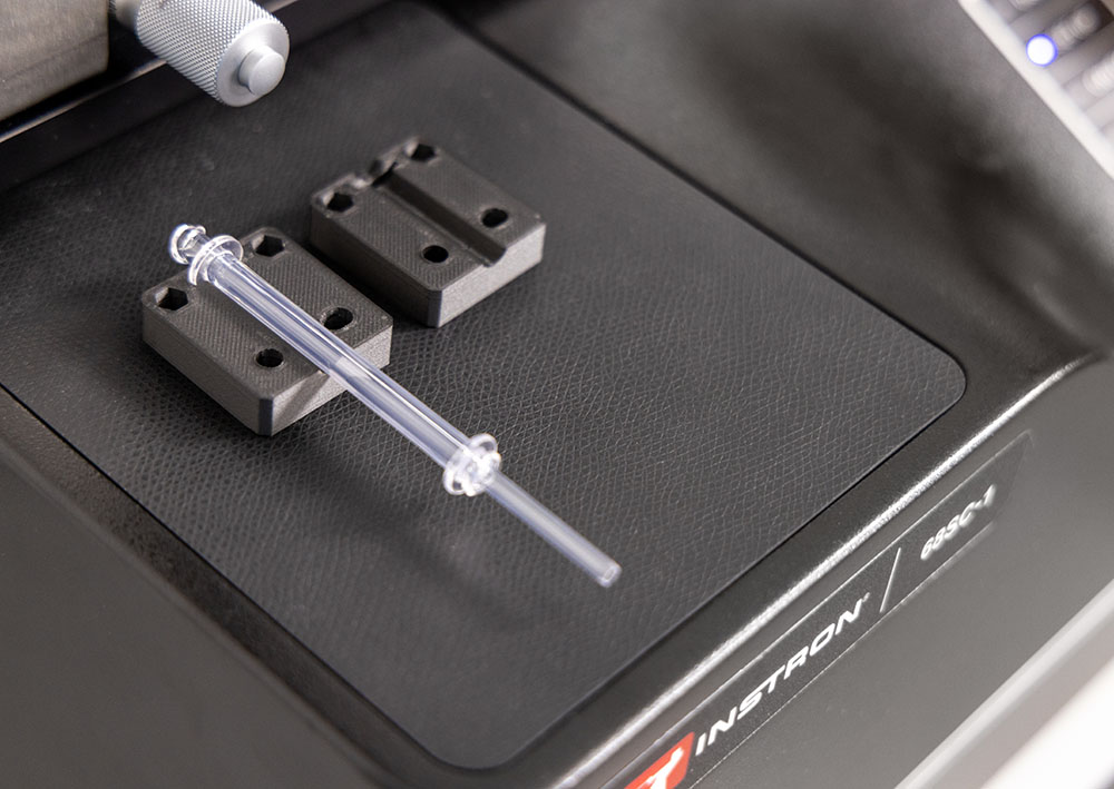
Instron 的 ISO 80369 试验系统建立在我们先进的具有双轴测试能力的 6800 系列万能材料试验系统上,具有卓越的性能和灵活性,可支持广泛的医疗设备测试。
通过将机械性能测试与加压泄漏性能测试整合于一台设备之中,该试验系统显著提升了测试效率、缩短了评估时间,并减少了测试装置的使用量。其模块化设计可适配注射器、静脉输液接口及连接器等多种配件,确保针对不同装置的几何形状实现精准对中与灵活适配。借助专为标准及定制装置测试设计的 Instron ISO 80369 试验系统,全面释放您的测试潜能。

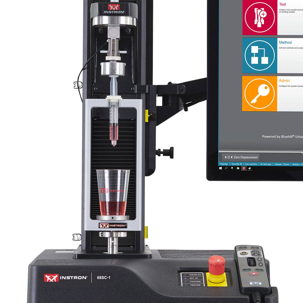
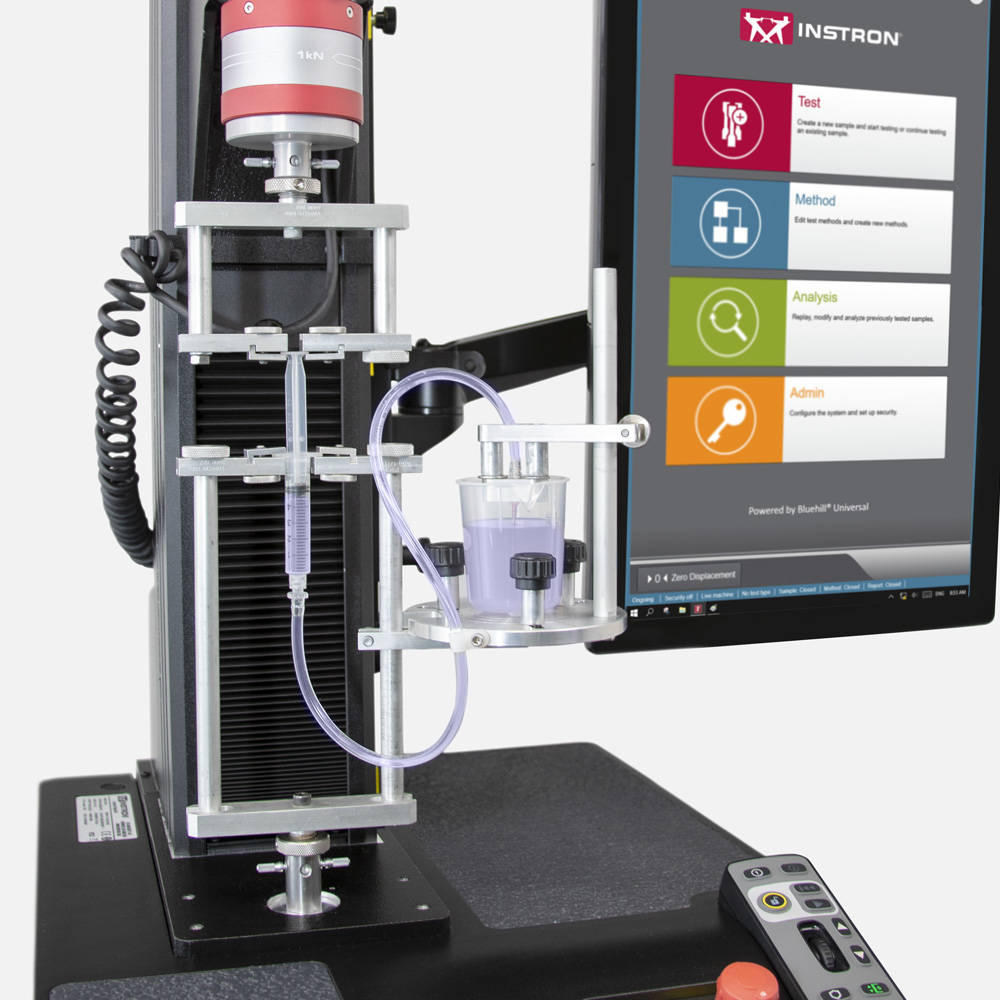
我们的注射器夹具系列旨在研究评估注射器和注射器/针头组合性能所需的力。与测试系统结合使用的夹具可以确定操作设备所需的力,特别是松脱力和滑行力。
CP131100 通用注射器工装可适用于 1 ml 至 50 ml 之间的各种常见注射器尺寸。可调式夹持机构使操作人员可以轻松调整以适配多种注射器尺寸,非常适合测试实验室使用。2870-001 注射器工装设计简单,在测试过程中使用特定卡槽支撑注射器法兰。
我们还提供单独的注射器测试工装,目录编号为 2870-003,专用于满足 ISO 7886-1 Annex G 对一次性使用无菌皮下注射器的测试要求。
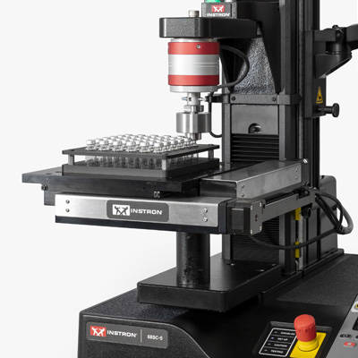
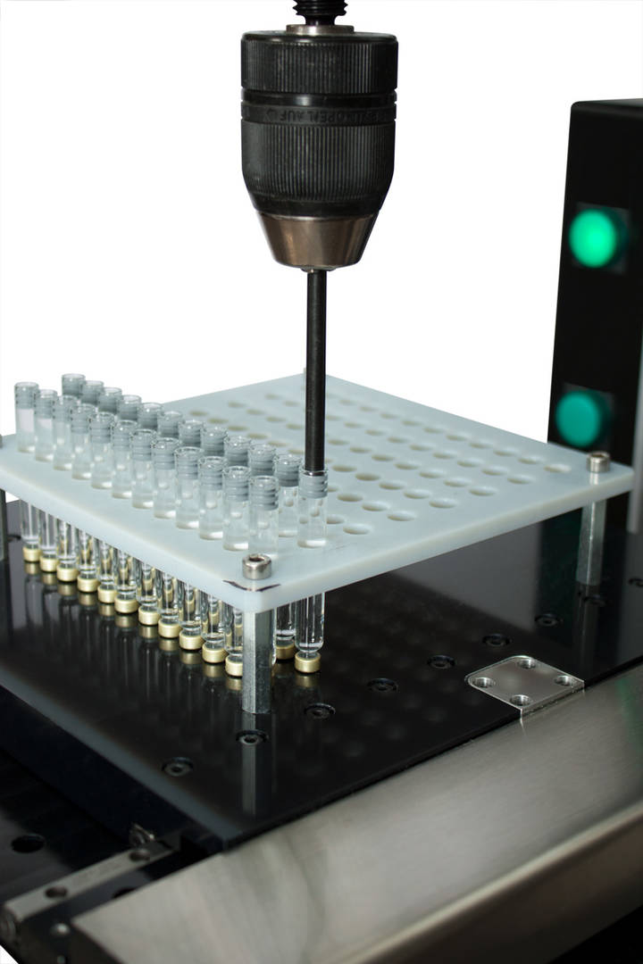


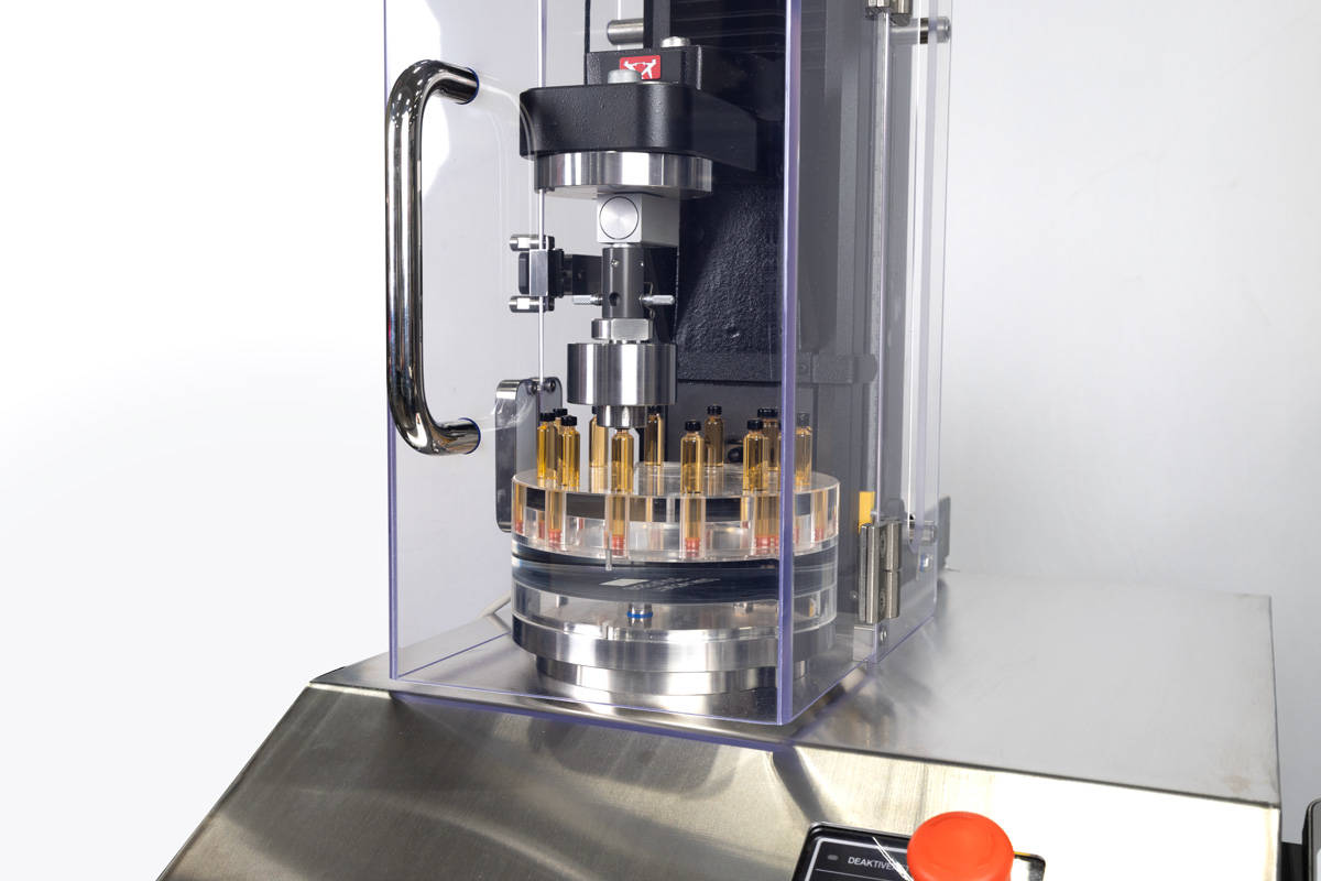
Instron 的自动化转盘试验系统采用创新的、适应性强的设计,用于测试医用小瓶、药筒和预灌封注射器。该系统占地面积小,可以放在标准实验室工作台上,即使是最小的实验室也能实现自动化。它采用易于擦拭的表面和不锈钢盖设计,适用于生物医疗环境。通常配置为自动测试残余密封力(RSF)和压缩测试。
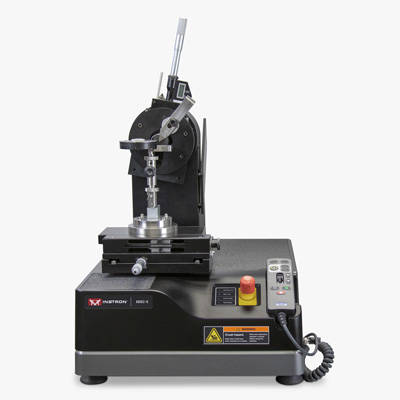
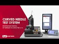
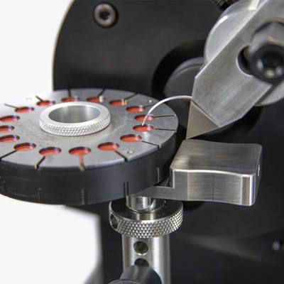
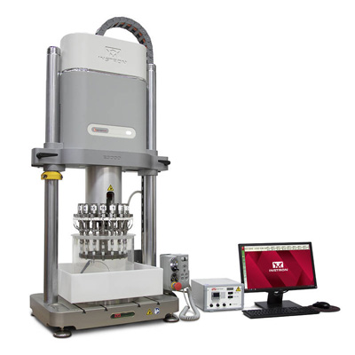

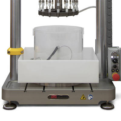
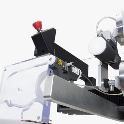
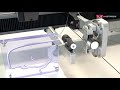

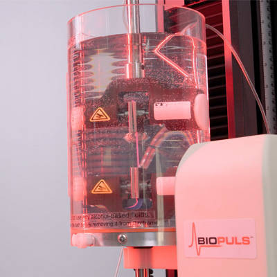
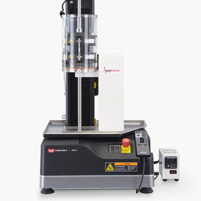
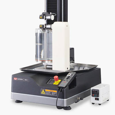
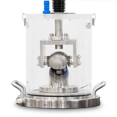
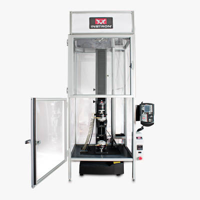

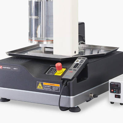
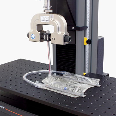
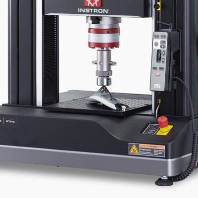
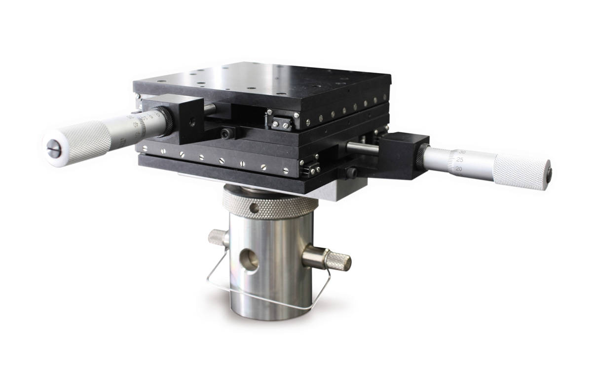
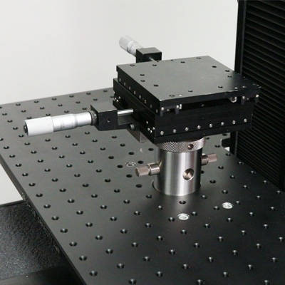

Instron 提供多种夹具,适用于对各种微电子部件和附件(包括引线、导线和不规则形状的产品)进行拉伸试验。
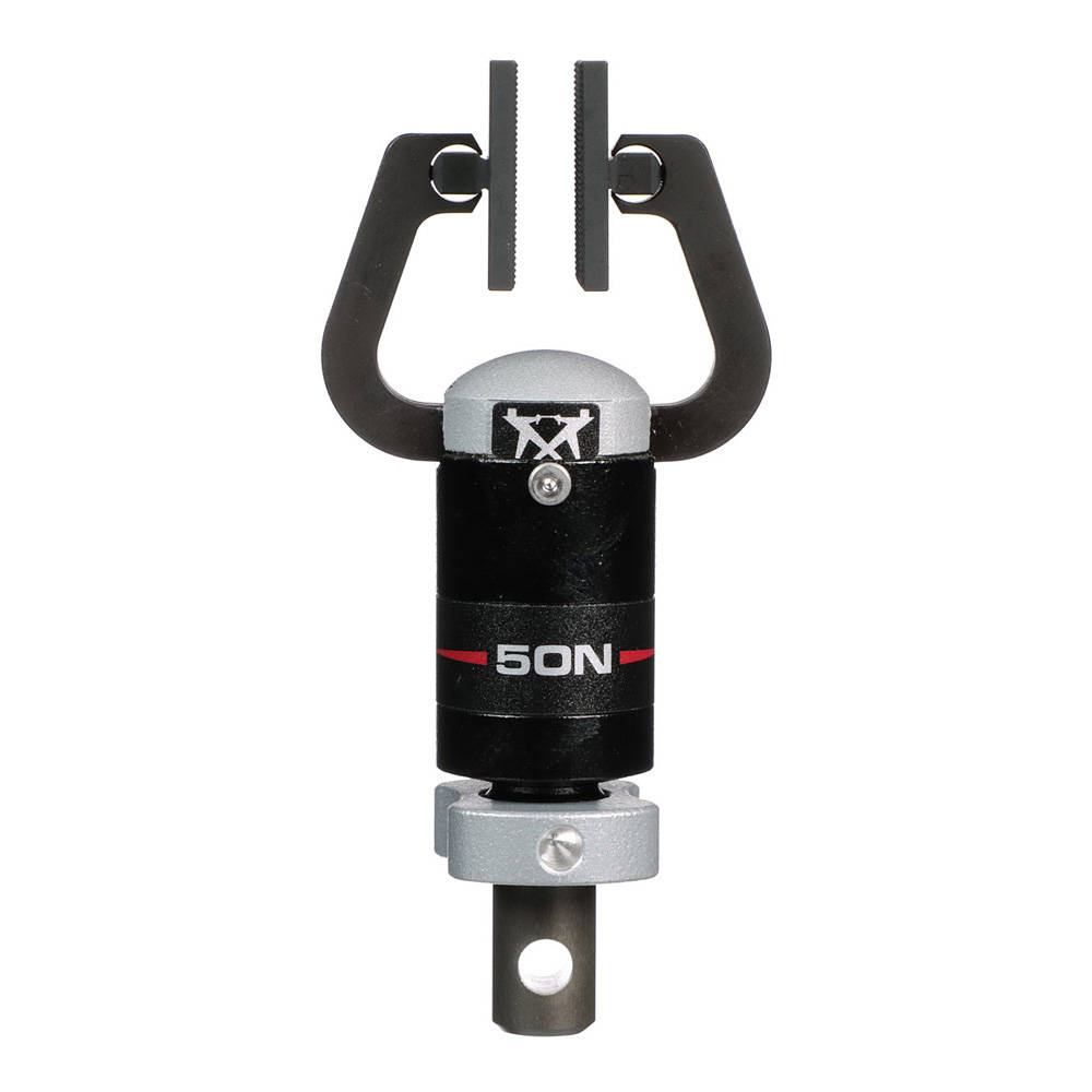
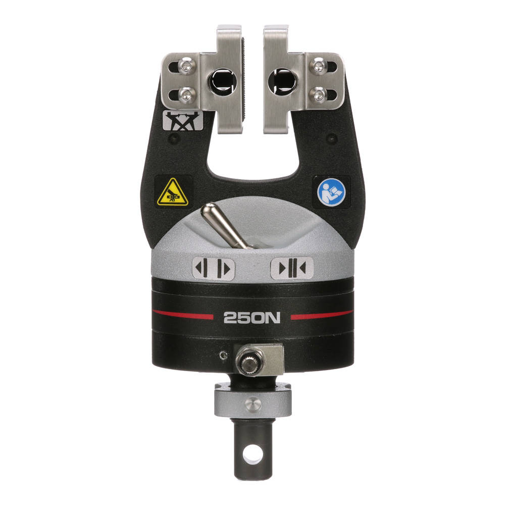
| 可用型号 | |
| 夹持力 | 型号 |
| 50 N | 2712-051 |
| 250 N | 2712-052 |
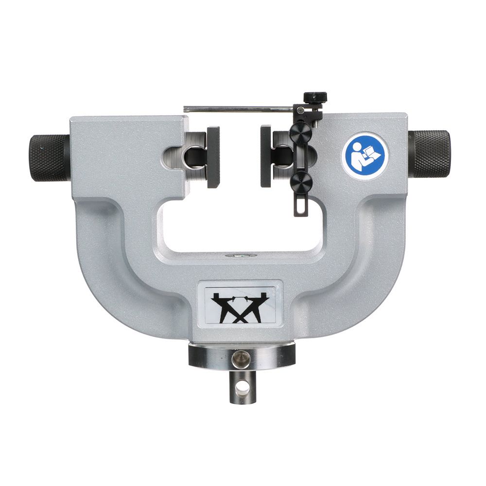
| 可用型号 | ||
| 夹持力 | 最大夹面开口 (带锯齿夹面) | 型号 |
| 100 N | 35 mm | 2710-111 |
| 500 N | 35 mm | 2710-112 |
| 1 kN | 36 mm | 2710-113 |
| 2 kN | 36 mm | 2710-114 |
| 5 kN | 46 mm | 2710-115 |
| 10 kN | 46 mm | 2710-116 |
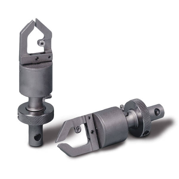
| 规格 | ||
| 夹持力 | 最大试样厚度 | 型号 |
| 10 N | 0.8 mm | 2712-101 |


| 规格 | ||
| 夹持力 | 型号 | |
| 10 N | 2860-001 | |
复合材料的表征需要在不同载荷条件下进行一系列测试,例如拉伸、压缩、剪切、挠曲和剥离。Instron 提供一系列符合 ASTM、ISO、EN 及其他测试标准要求的高性能复合材料测试工装。


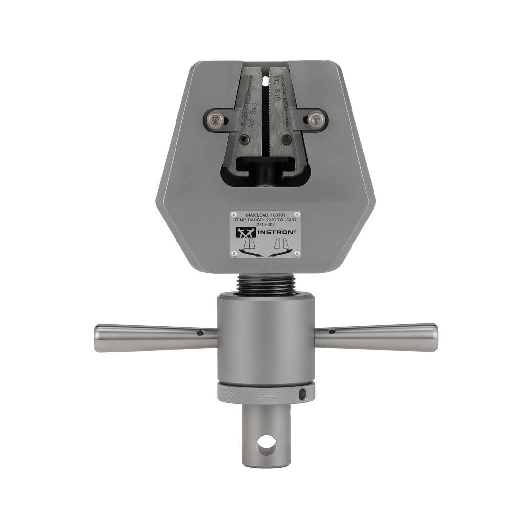
手动和液压两种类型的夹具均可在广泛的温度范围内使用。对于复合材料测试,推荐使用夹具体移动式的手动或液压楔形拉伸夹具 - 既能牢牢夹持试样,又能保持精确且可重复的对中精度,满足航空航天测试的 Nadcap 标准要求。配套适配器可将多种复合材料测试工装与夹具连接,无需在更改测试设置时拆卸夹具,从而减少流程中断次数并提升测试效率。
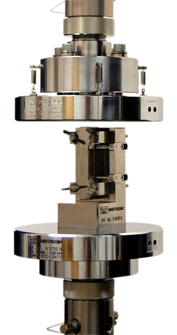
| 概述 | |
| 常用标准 | ASTM D695、ASTM D3846、Boeing BSS 7260、SACMA SRM-1、prEN 2850、ISO 14126 |
| 目录编号 | S4931A、CP108932、CP114221、CP114215、CP115010、CP115011、CP114249 |


| 概述 | |
| 常用标准 | ASTM D6484、ASTM D6484M、Boeing BSS 7260 |
| 目录编号 | CP113777、CP113778、CP113779、CP113780 |

复合材料 V 型缺口梁剪切测试工装
Instron 剪切测试工装专为复合材料的面内剪切或层间剪切试验而设计。V 型缺口梁法(更普遍称为 Iosipescu 剪切法)于 1993 年被纳入 ASTM D5379 标准,而 V 型缺口轨道剪切法则是于 2005 年根据 ASTM D7078 标准推出。两种试验方法具有许多共同特征,且在试样设计中均采用独特的 V 型槽口 - 其作用是在槽口之间形成局部且近似均匀的剪切应力区。需要注意的是,ASTM D7078 和 D5379 中的两种工装在试样设计、载荷施加方式以及所得结果类型上存在显著差异。
| 概述 | |
| 常用标准 | ASTM D5379、ASTM D7078 |
| 目录编号 | S4685A、CP105207 |
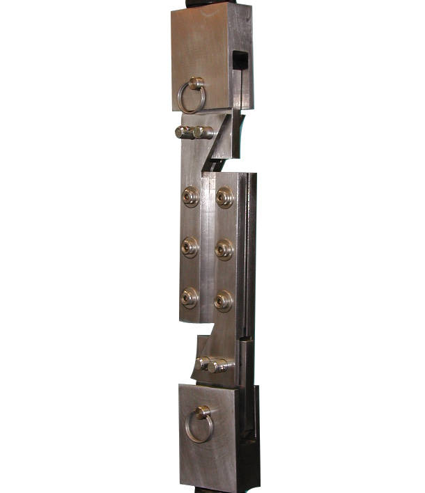
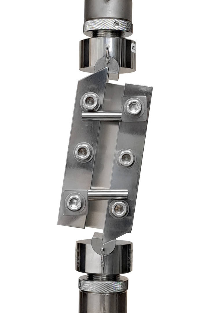
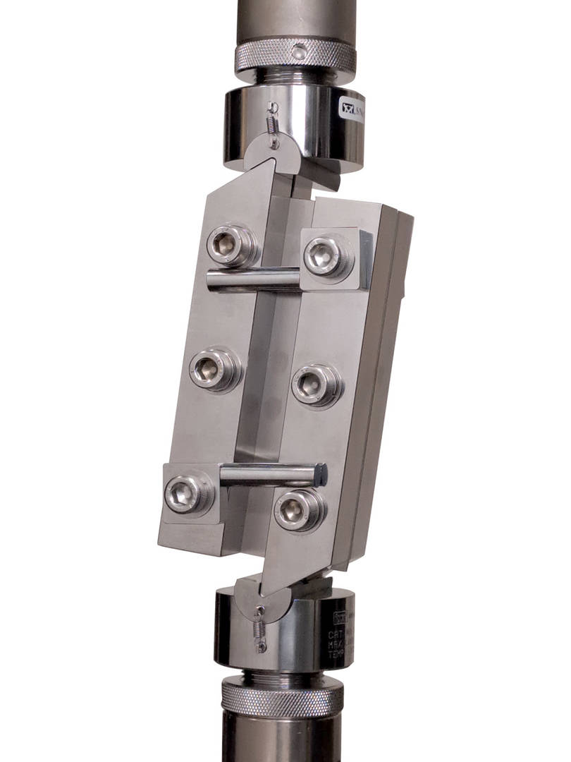
符合 ASTM D4255 标准的复合材料轨道剪切工装
ASTM D4255 描述了用于测定复合材料层压板的面内剪切强度的双轨道剪切和三轨道剪切方法。在双轨道测试(方法 A)中,层压板试样被夹持在上、下金属底板之间,然后施加剪切力。测量剪切应变需要在试样上使用应变片。有两种工装可供选择:一种以压缩模式进行,另一种以拉伸模式进行。试验中包含试样模板,以确保试样上孔的位置精确。
| 概述 | |
| 常用标准 | ASTM D4255 |
| 目录编号 | S4695A、S4695B |
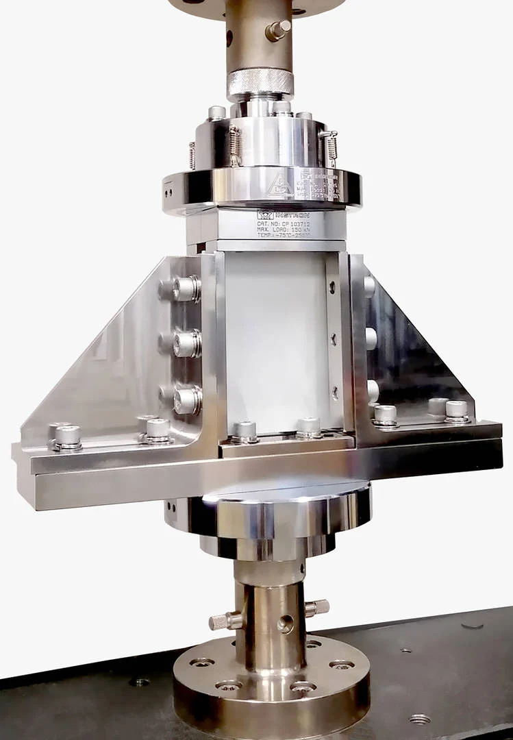
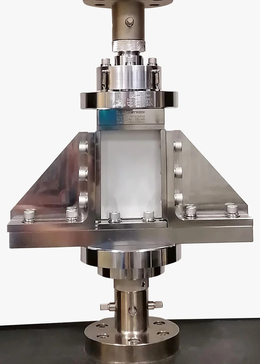
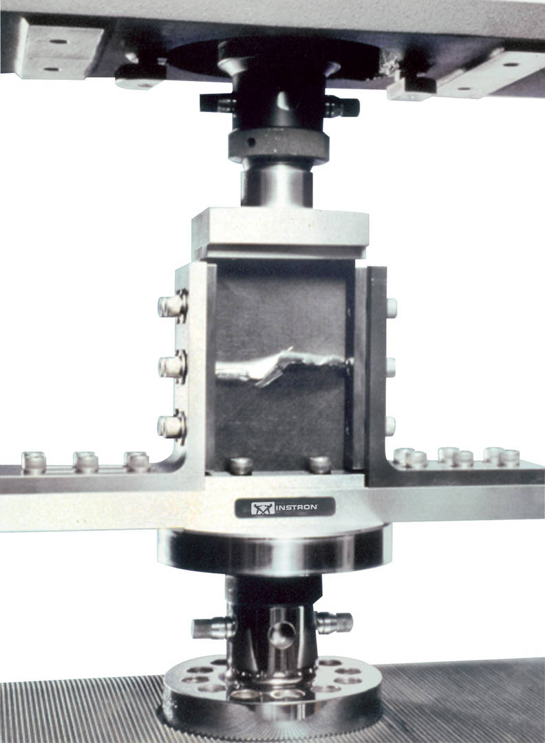
| 概述 | |
| 常用标准 | ASTM D7137 / 7137M、Boeing BSS 7260 |
| 目录编号 | S5385A、CP103712 |
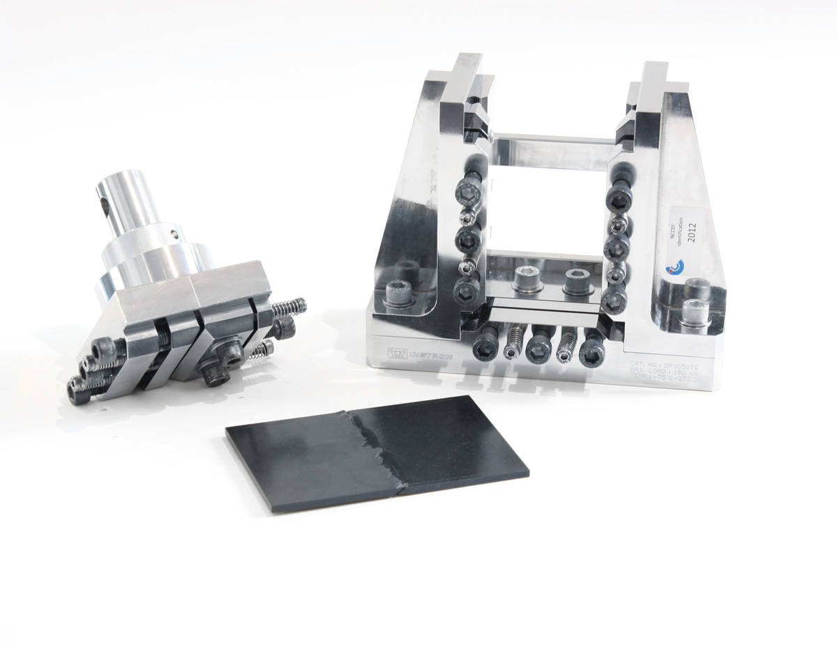
| 概述 | |
| 常用标准 | AITM 1-0010 |
| 目录编号 | CP105079 |
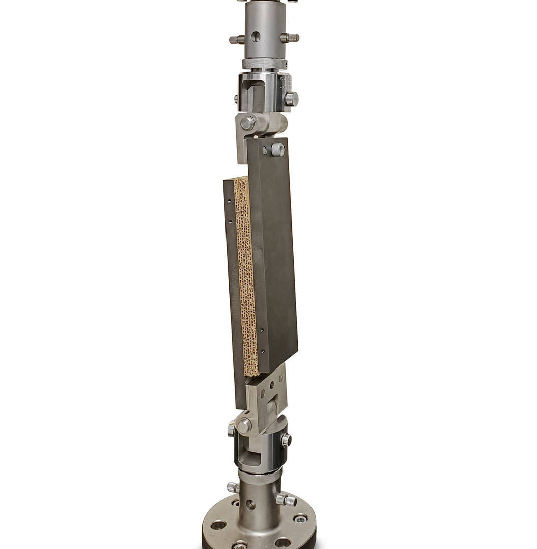
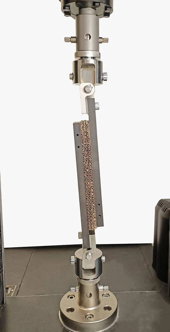
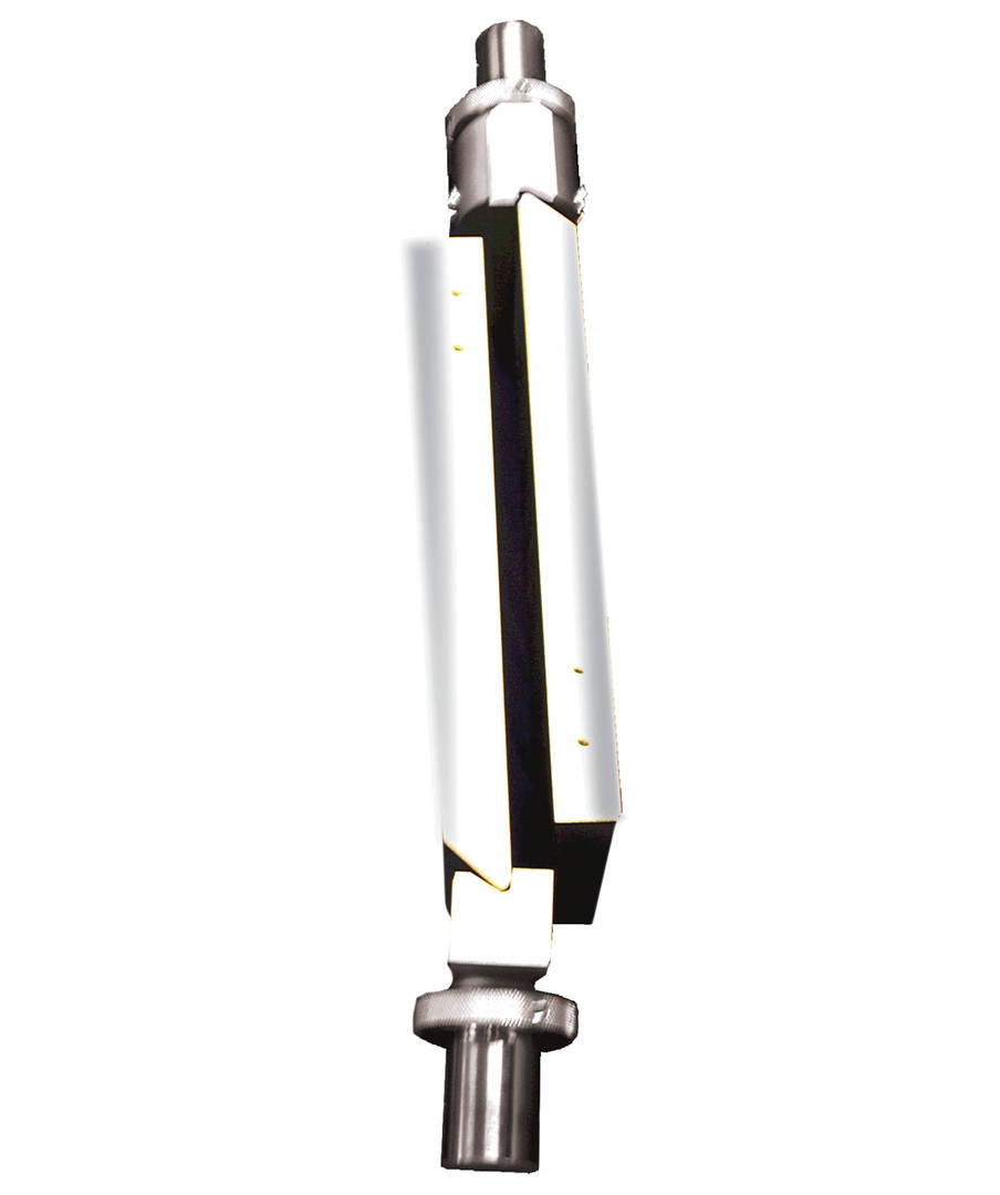
| 概述 | |
| 常用标准 | ASTM C273 |
| 目录编号 | S4681A、S4682A |
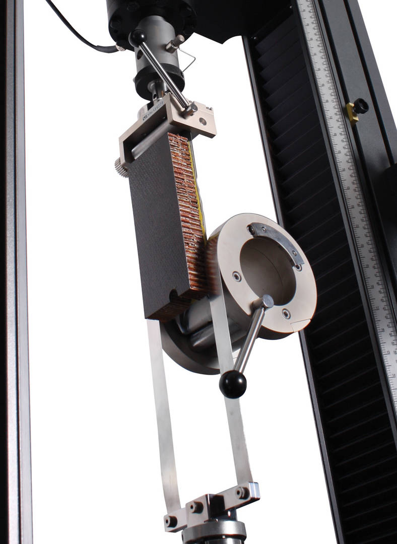
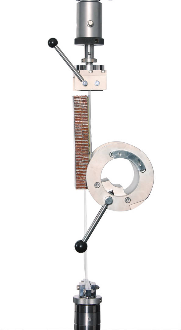
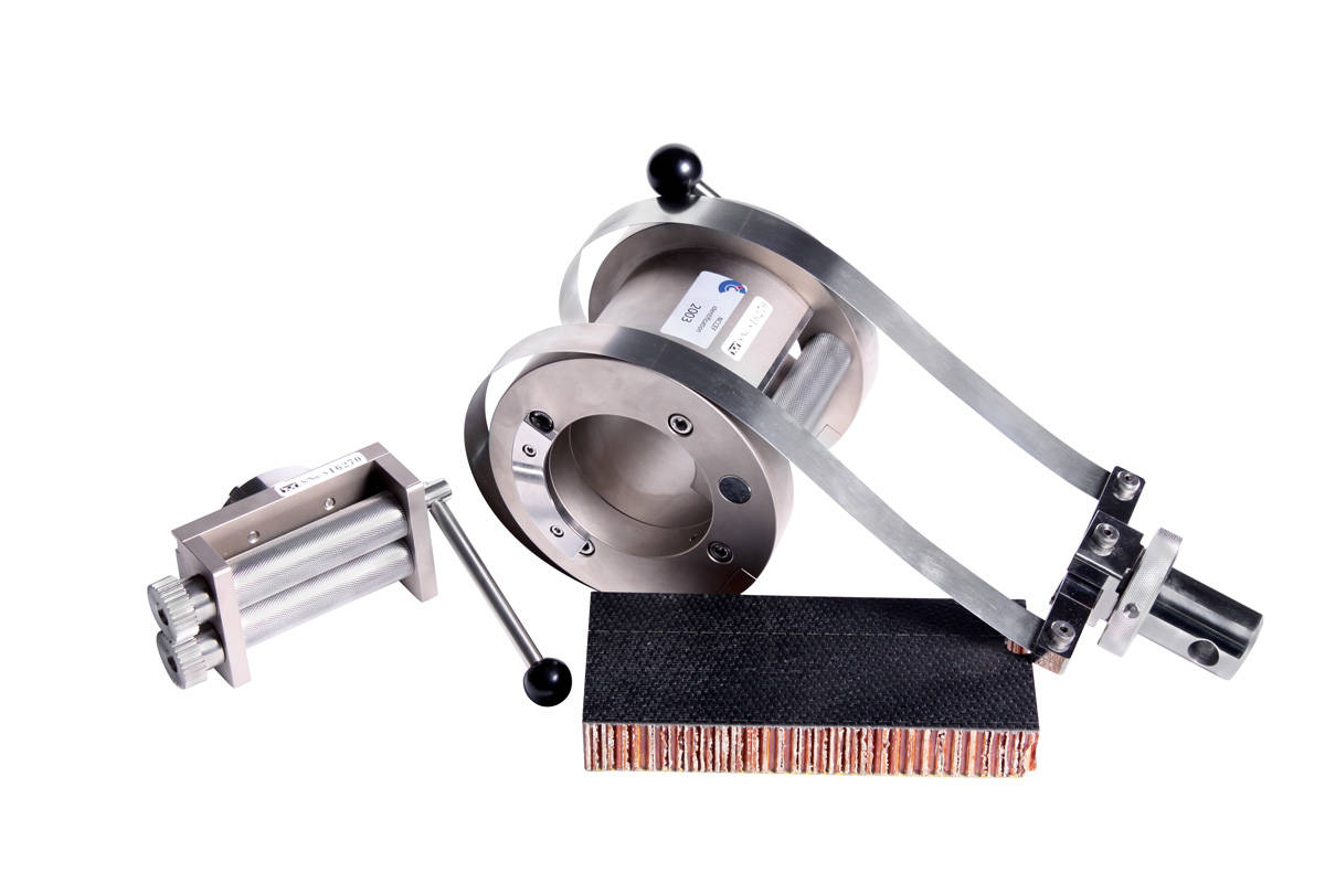
滚筒剥离测试工装
针对粘合剂的滚筒剥离试验可以测量蜂窝板夹层芯板和面板之间的粘合强度。
| 概述 | |
| 常用标准 | ASTM D1781、EN 2243-3 |
| 目录编号 | S4680A、S4680C、CP108963 |

120 和 350 ohm 应变片适配器
从航空航天到建筑领域,应变片在多种行业中用于材料和结构测试中的应变测量。这些应变片适配器可使单个应变片适配任何标准 Instron 应变通道。应变片适配器包含电桥完成电阻和电气标定电路,应变片引线通过弹簧加载端子连接至适配器,支持 2 线和 3 线应变片连接。该适配器兼容应变系数在 1.5-2.5 之间的应变片,多个应变片需搭配多个适配器,且适配器使用数量不超过试验系统配备的最大应变通道数。
| 概述 | |
| 目录编号 | 2210-891、2210-892 |
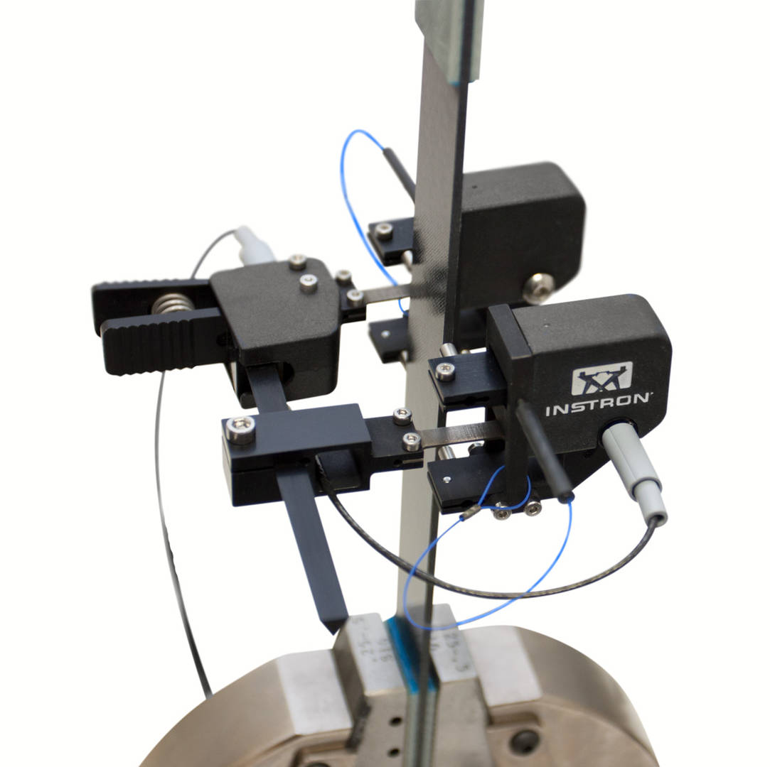
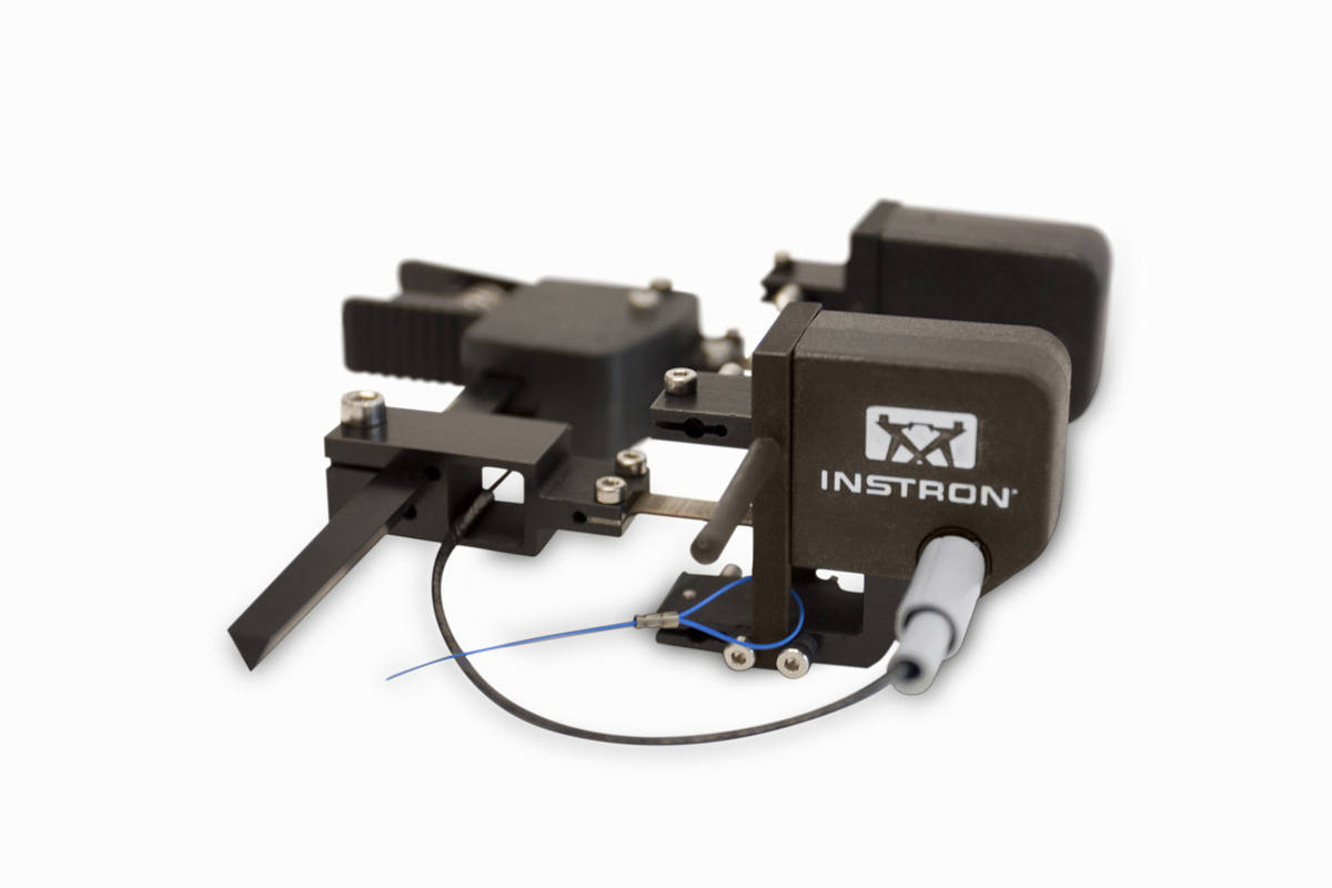
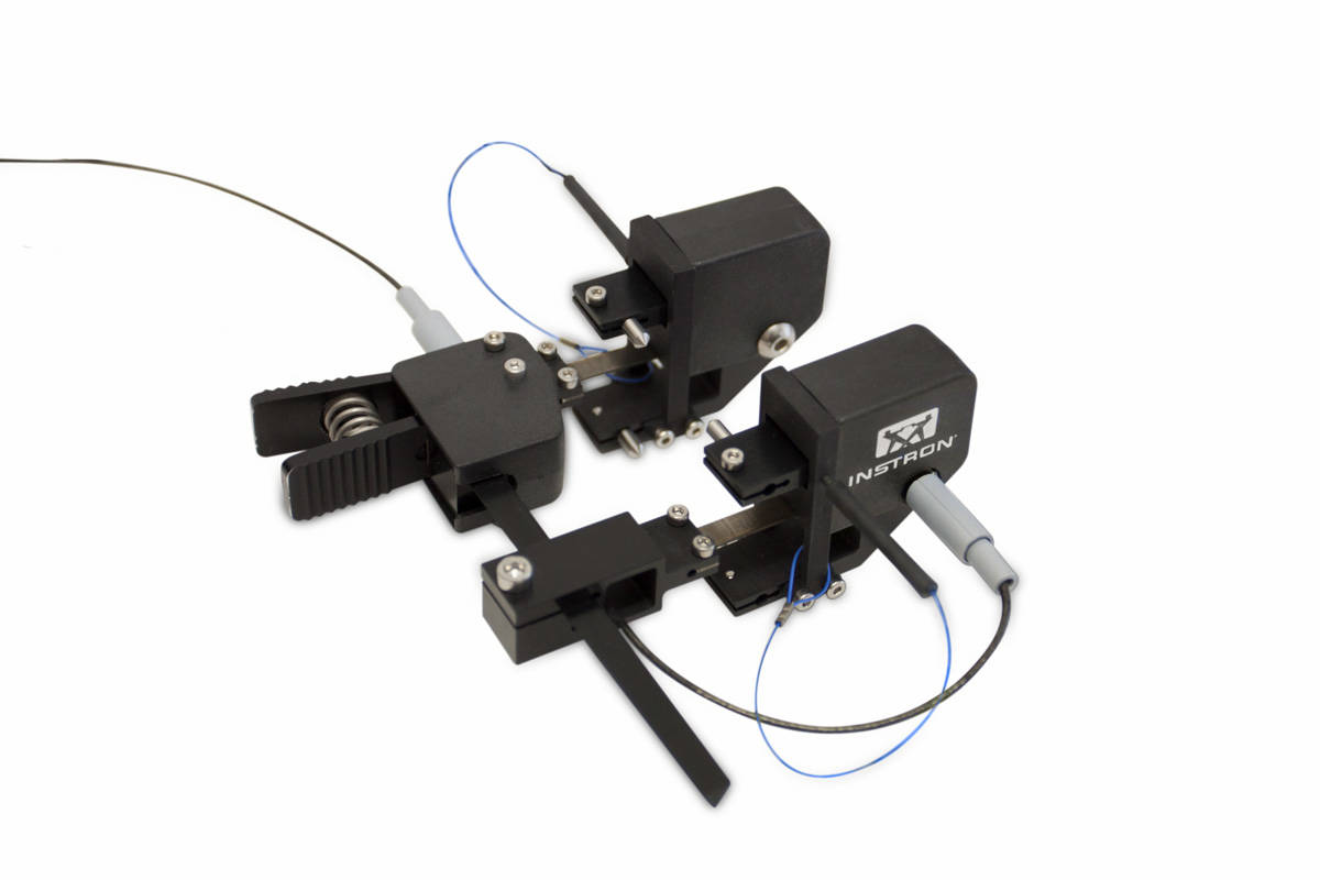
双轴引伸计
一系列双轴和平均轴向引伸计专门针对测量复合材料试验中的应变进行了优化。这些引伸计支持简单的单手操作,并包含自动电子标定和传感器识别功能,包括独特的数字序列号。所有引伸计都可以测量试样两侧的轴向应变。使用平均轴向应变可以校正由于未对中导致的任何试样弯曲,从而一致且准确地确定模量。双轴版本测量横向应变,并支持测定泊松比和面内剪切应变。
| 概述 | |
| 标准 | 符合 ASTM E82 B-1、ISO 9513 0.5 级和 ISO 527(附录 C) |
| 目录编号 | 2650-561 |
这些夹具设计用于配合万能试验系统执行各种剥离、穿刺、顶破和摩擦系数测试。
| 概述 | |
| 目录编号 | 2820-035 |
| 相关标准 | ASTM B571, ASTM D2861 |
| 剥离角度 | 90° |
| 最大载荷 | 1 kN |
| 最大试样宽度 | 127 mm |
| 最大试样长度 | 250 mm |
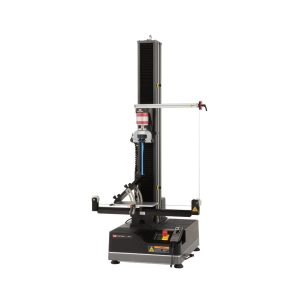
| 概述 | |
| 目录编号 | 2820-036 |
| 相关标准 | ASTM B571, ASTM D2861, ASTM D3330(方法f), ASTM D6252, ASTM D6862 |
| 剥离角度 | 30°, 45°, 60°, 90°, 130°, 150° |
| 最大载荷 | 1 kN |
| 最大试样宽度 | 130 mm |
| 最大试样长度 | 250 mm |
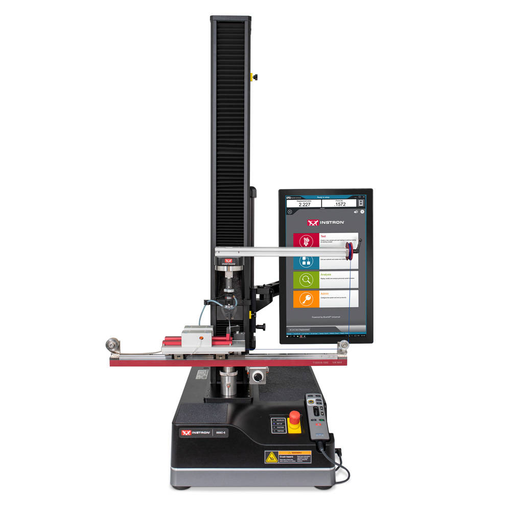


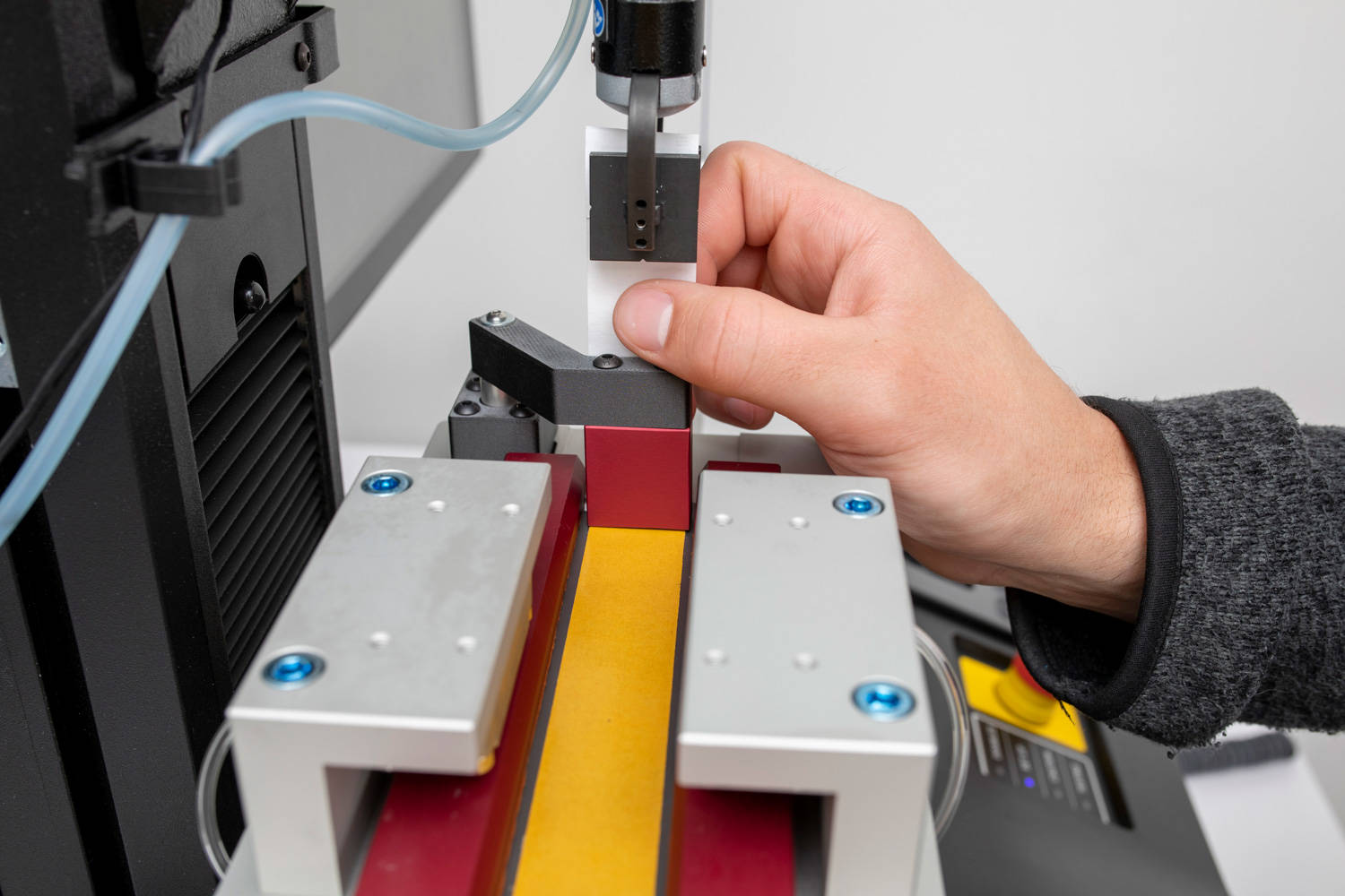
90° 剥离工装的设计旨在帮助操作员快速且一致地对试样进行对中和夹紧,同时确保从始至终都能保持 90° 角度。通过改进后的夹持与试样对中辅助装置,该工装相较于传统的剥离工装提供了更好的可重复性以及更高的工作效率,并有效降低操作员的影响。这些优势使得气动工装比通过手动调节、夹持的 90° 剥离工装更受欢迎。
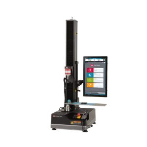
| 概述 | |
| 目录编号 | 2810-005 |
| 相关标准 | ASTM D1894, ISO 8295:2004 |

| 概述 | ||
| 目录编号 | 2820-101 | 2820-102 |
| 相关标准 | ASTM D3167 | ISO 4578, EN 1464, EN 2243-2 |
| 最大载荷 | 5 kN | 5 kN |

| 概述 | |
| 目录编号 | 2820-026 |
| 相关标准 | ISO 6133, IPC-TM-650 2.4.9 |
| 剥离角度 | 90° |
| 最大载荷 | 1 kN |

| 概述 | |
| 目录编号 | 2810-195 |
| 相关标准 | ASTM D3787, ASTM D6797, FED 191A |
| 最大载荷 | 10 kN |

| 概述 | |
| 目录编号 | 2810-501 |
| 相关标准 | ASTM D5748-95, ASTM D4649 |
| 最大载荷 | 4.4 kN |

| 概述 | |
| 目录编号 | S1-11855 |
| 相关标准 | MIL-STD-3010 |
| 最大载荷 | 2.5 kN |

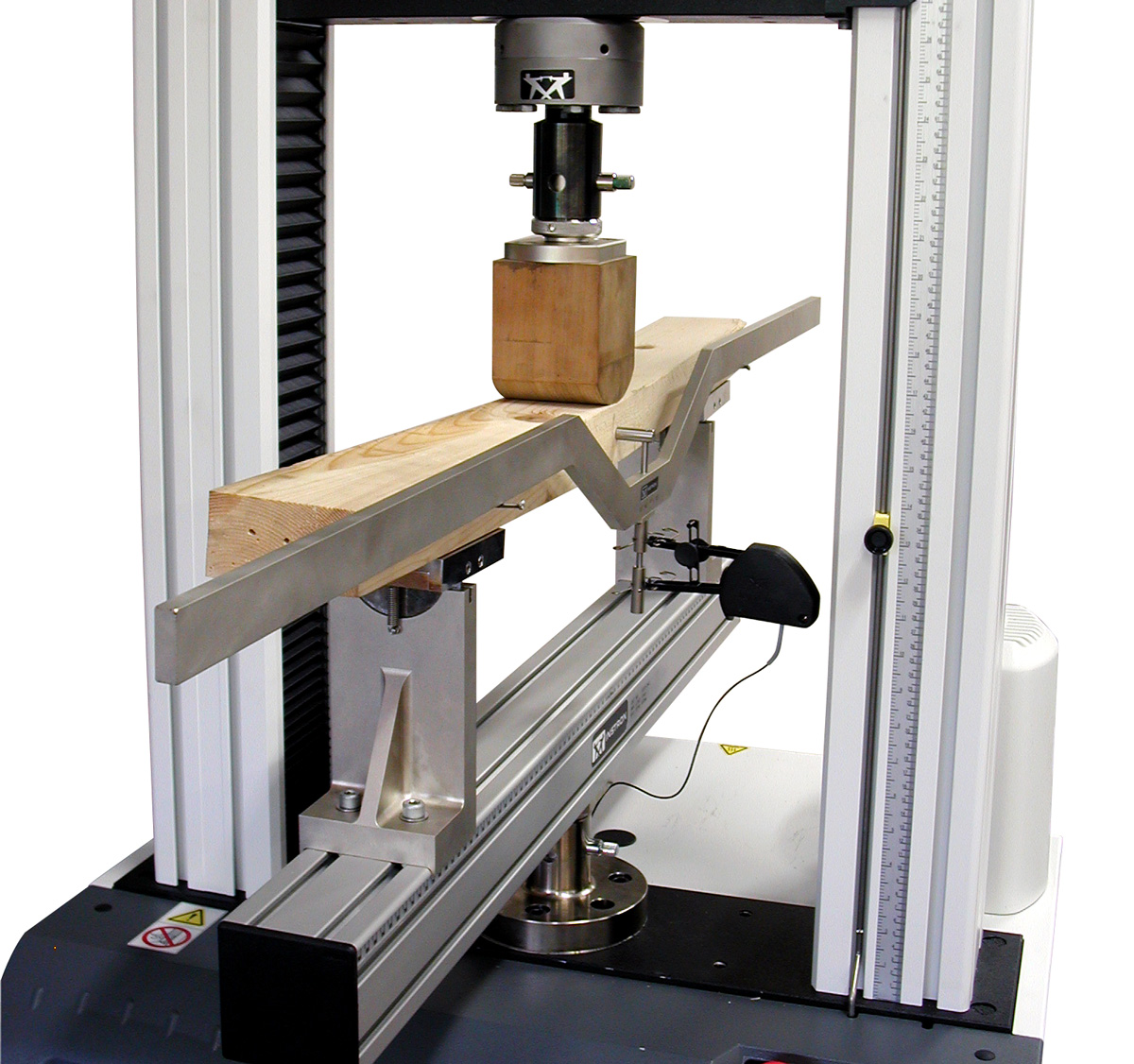

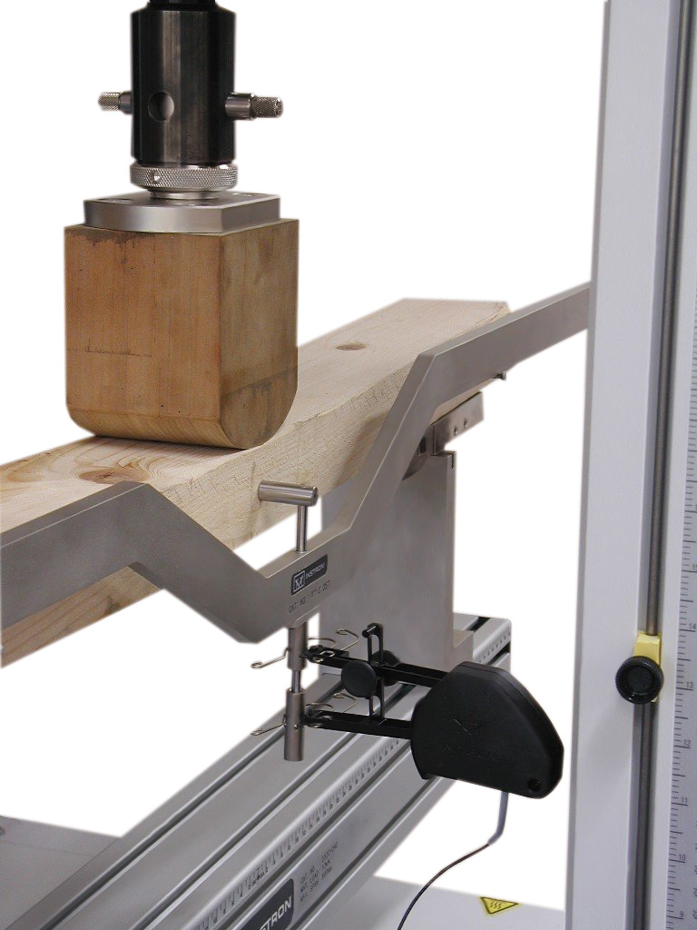
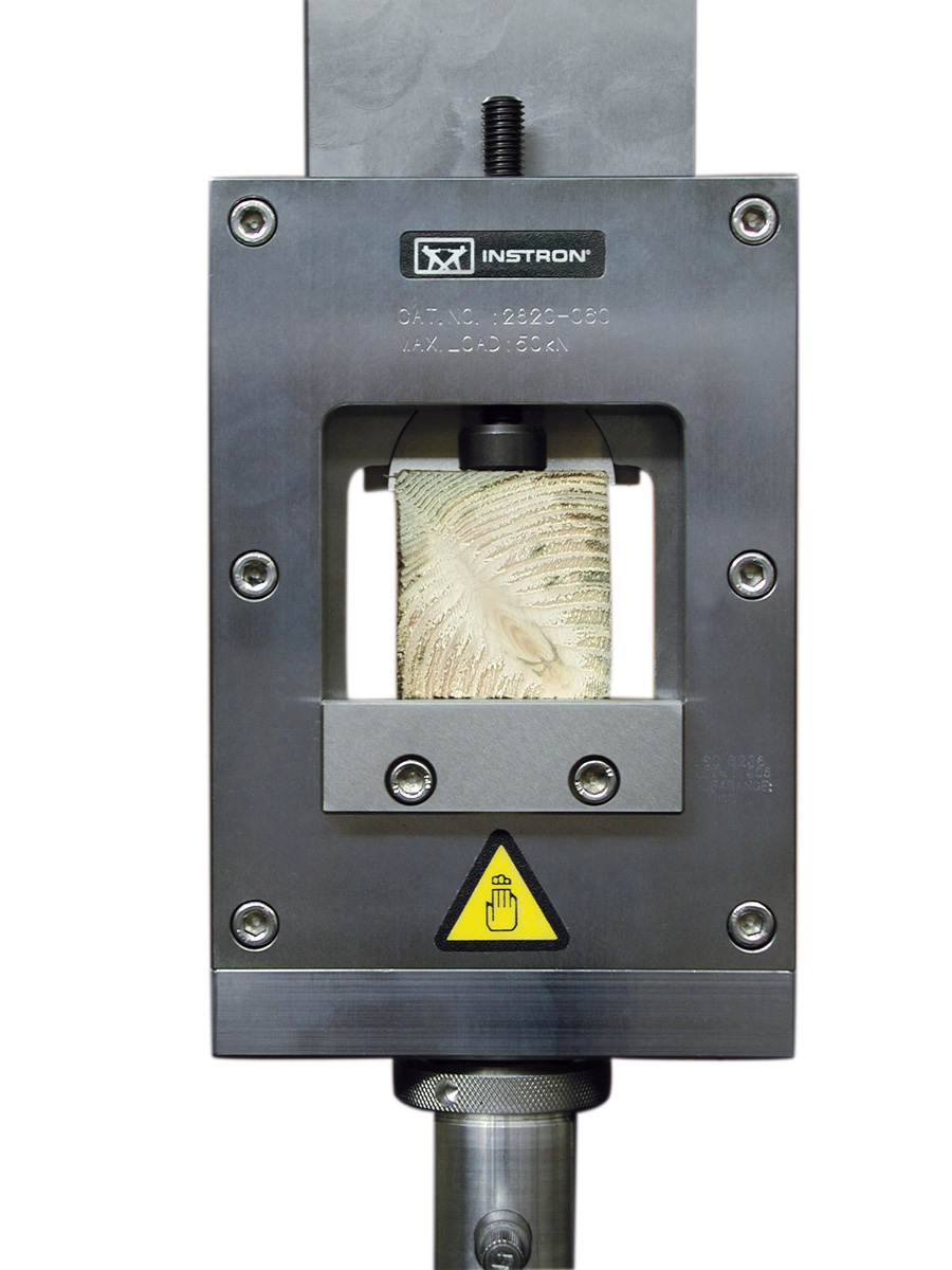
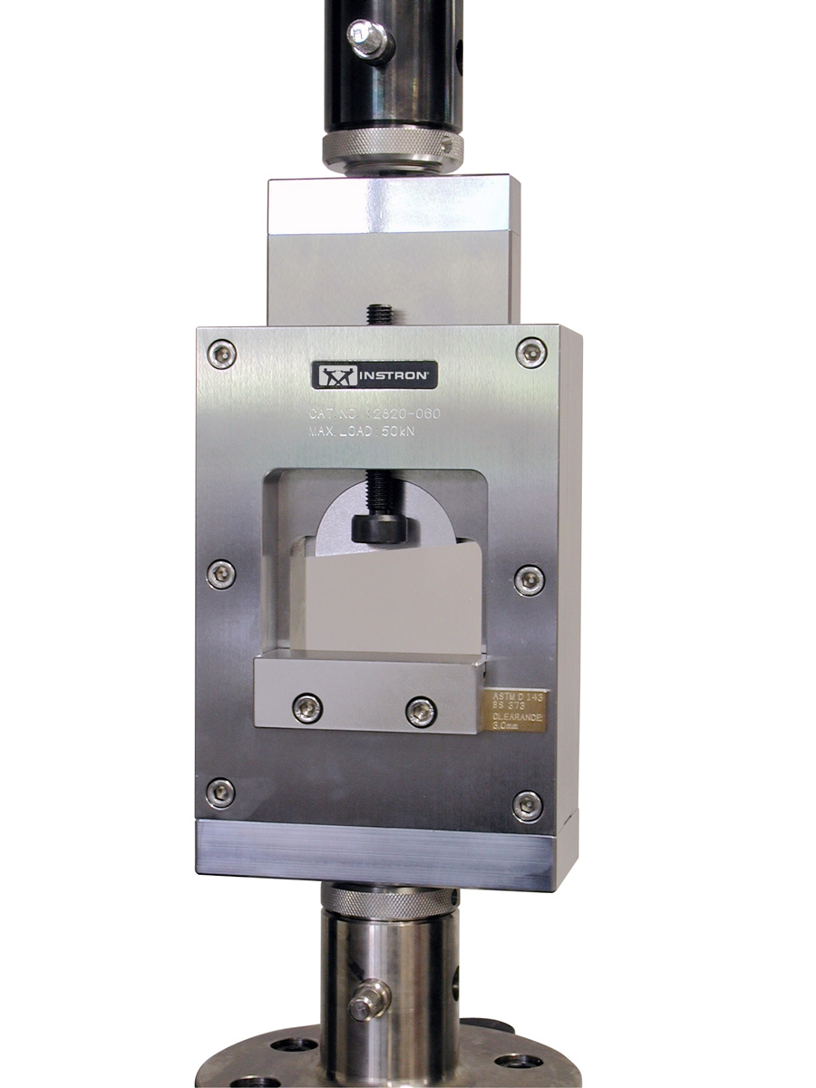

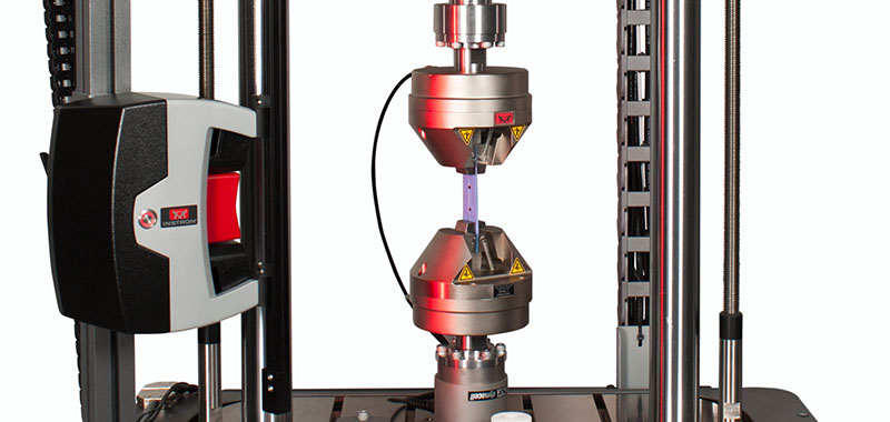
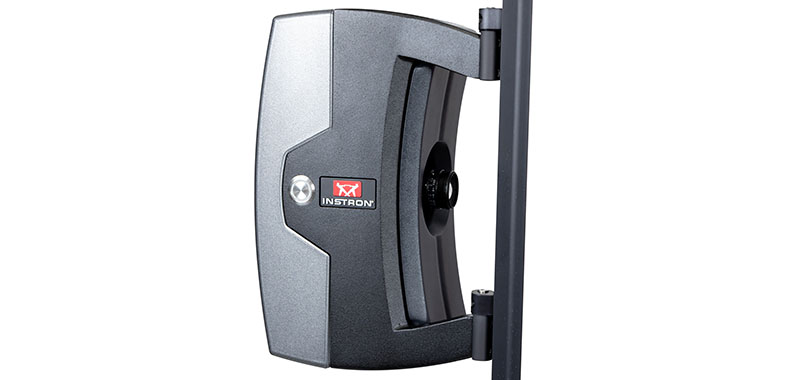
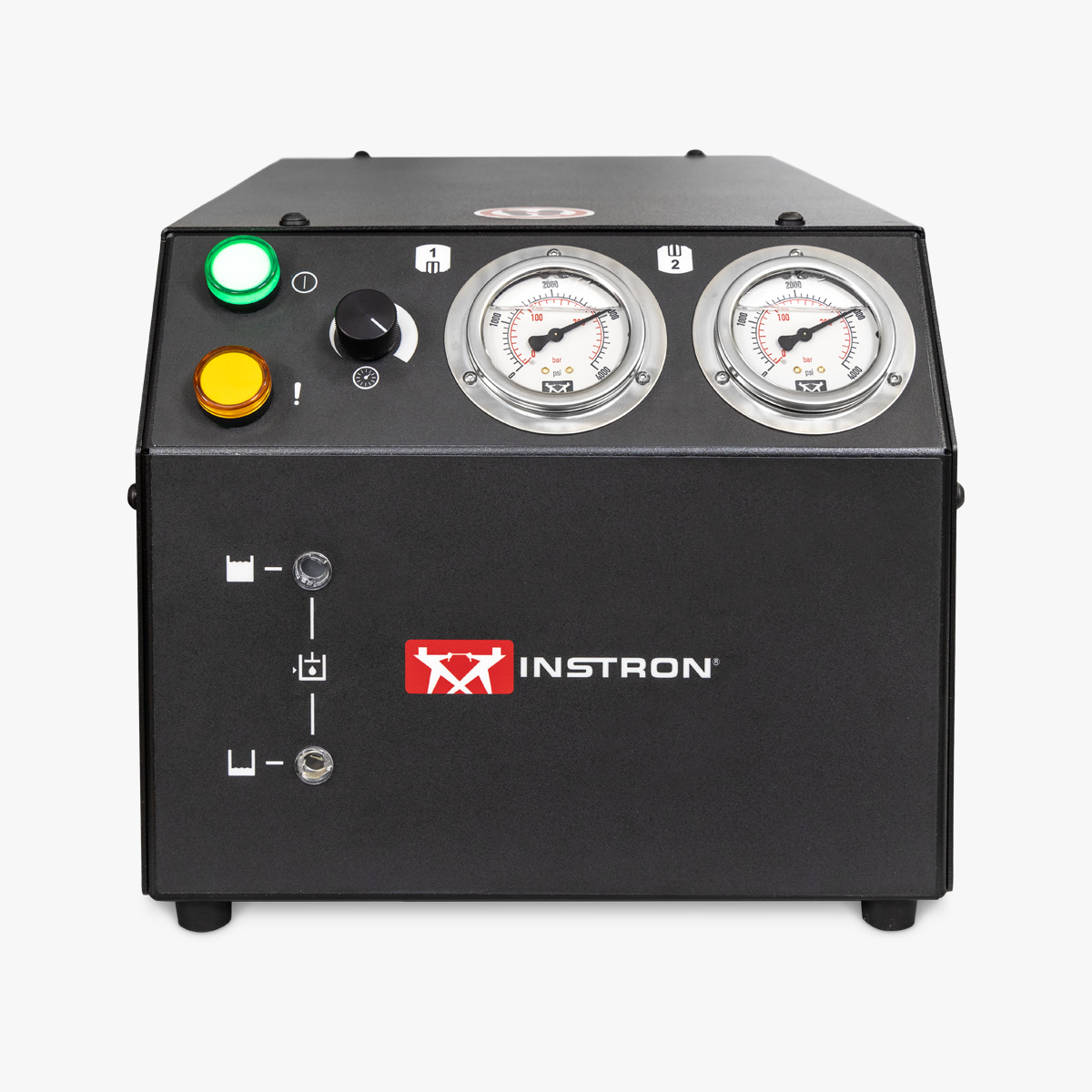

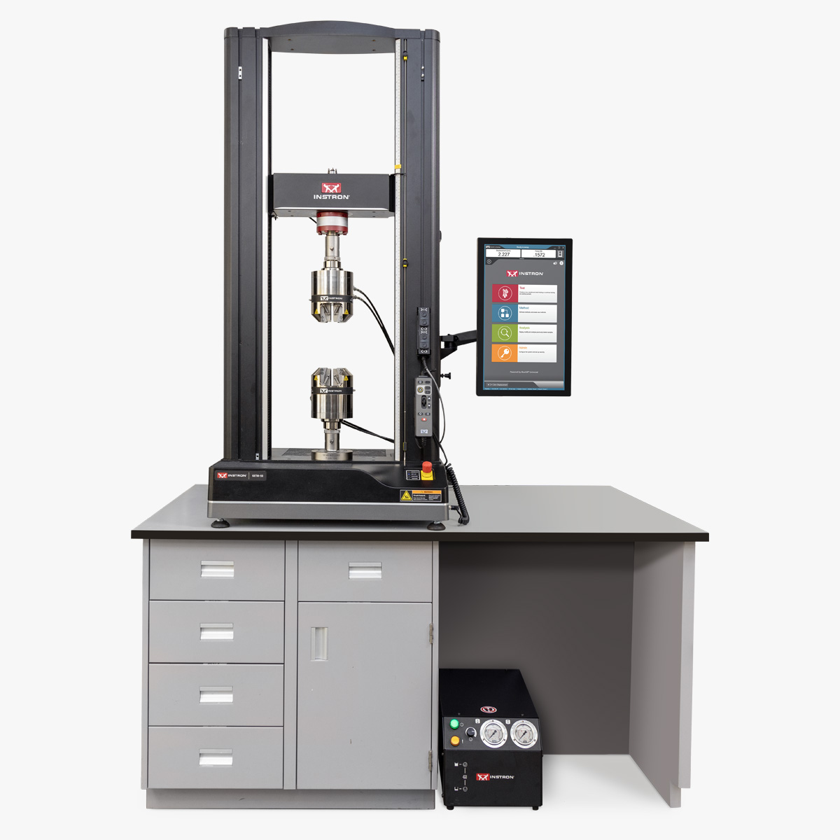

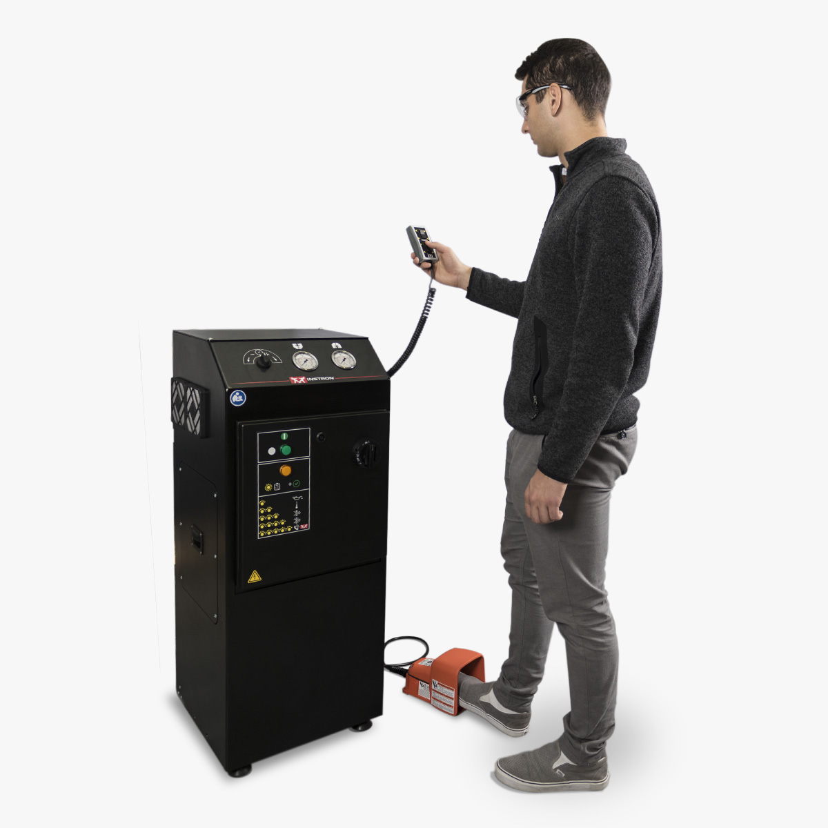


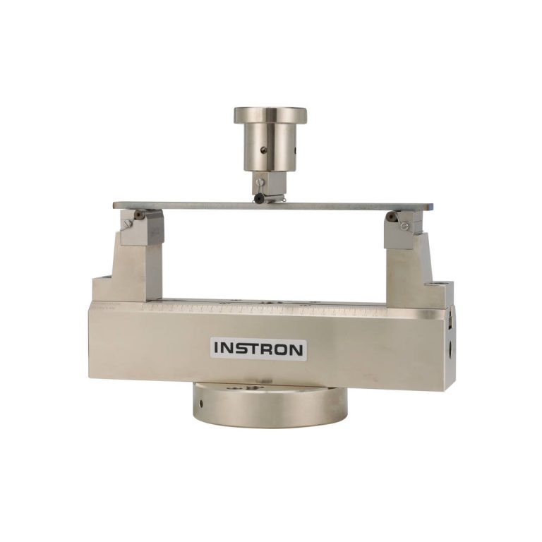


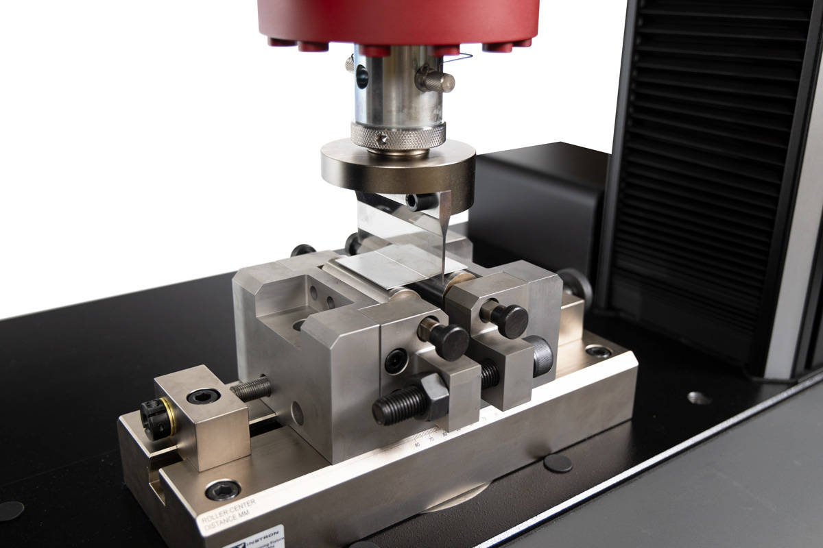
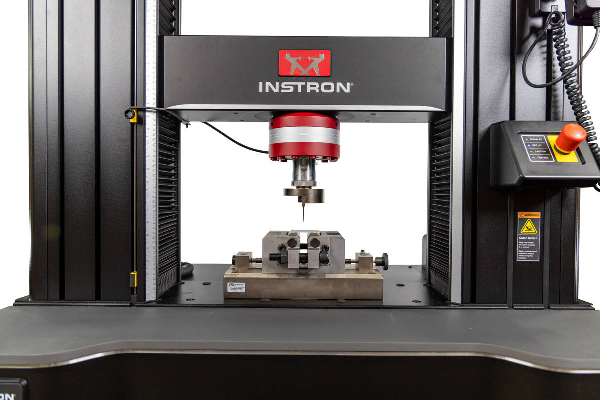
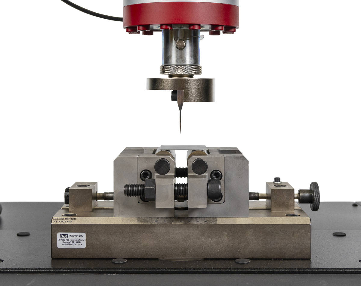


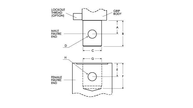


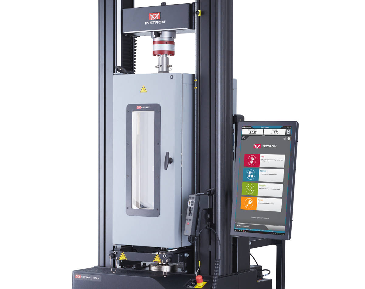

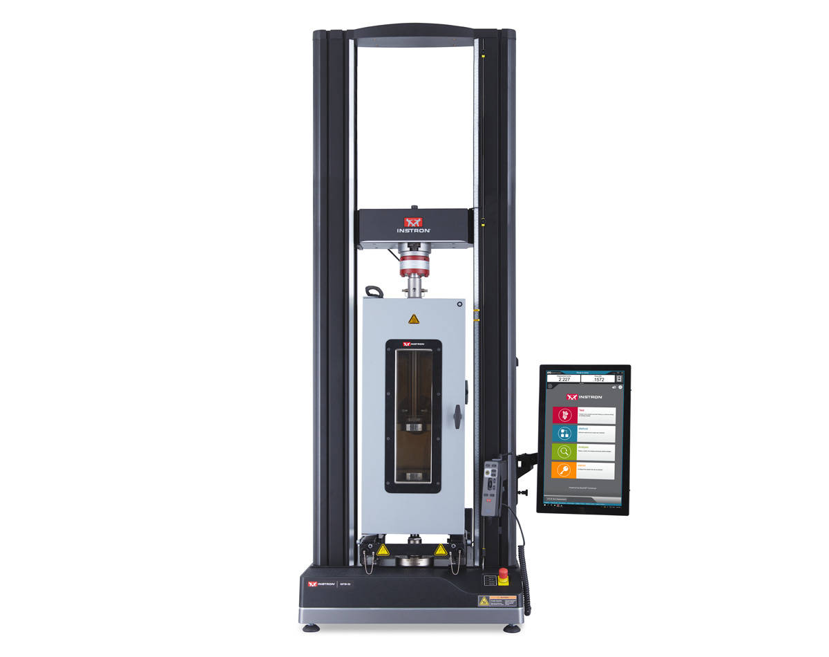
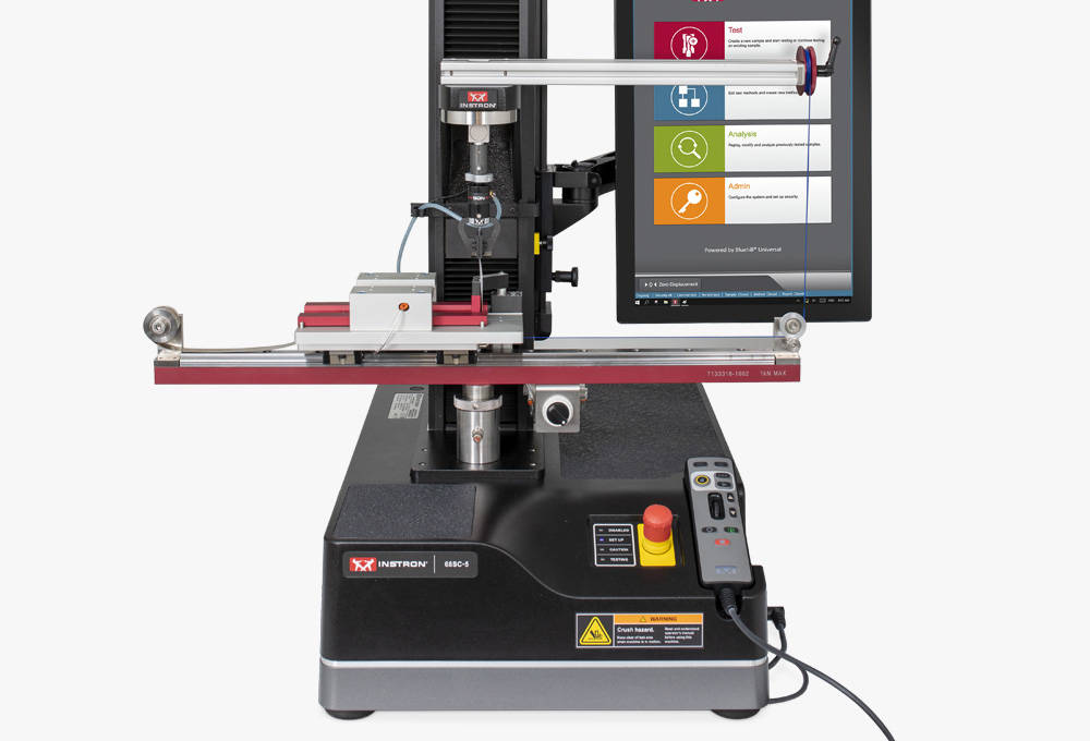

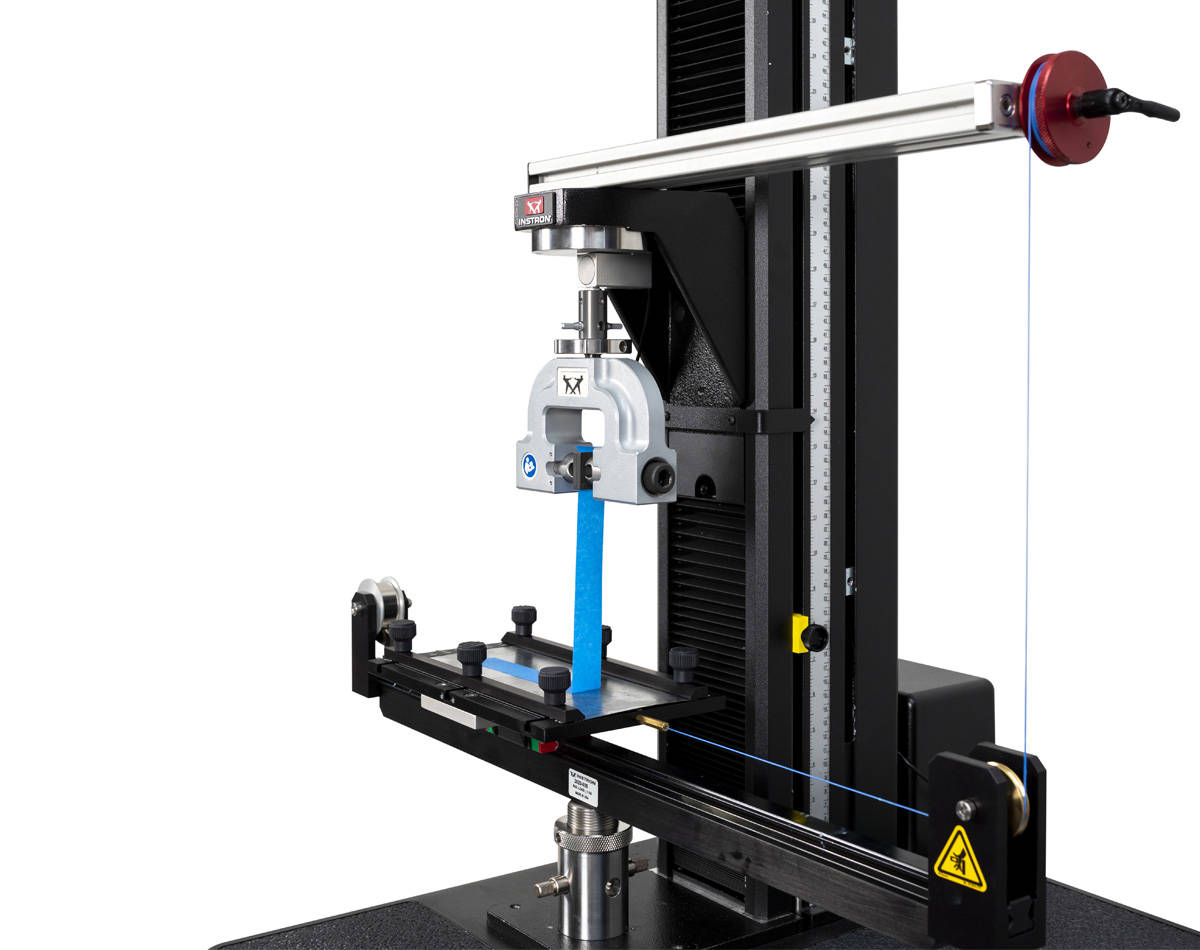
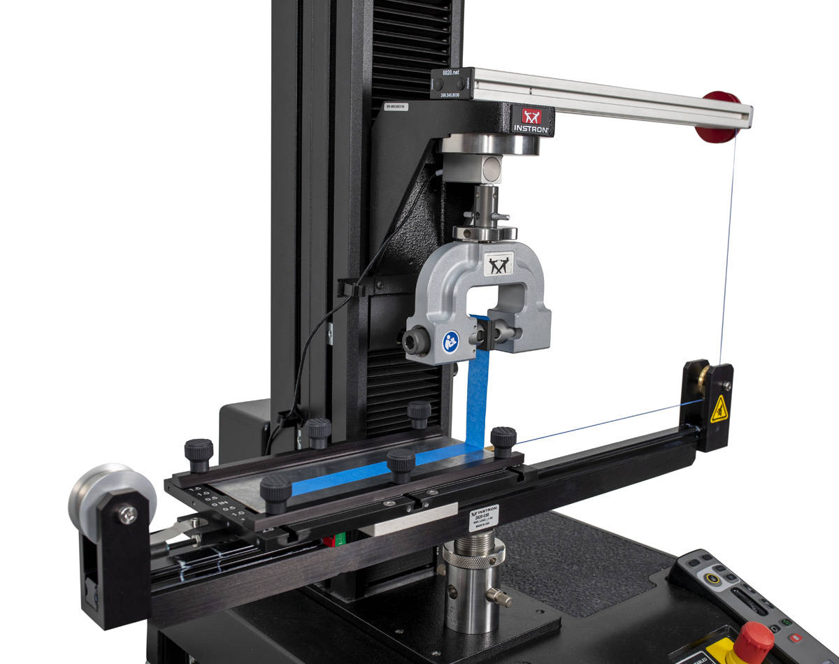
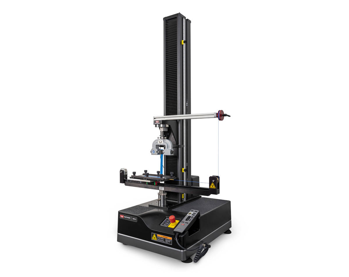
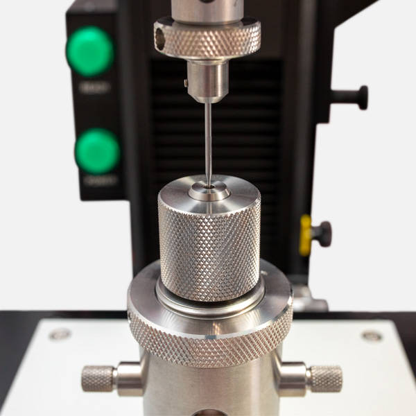

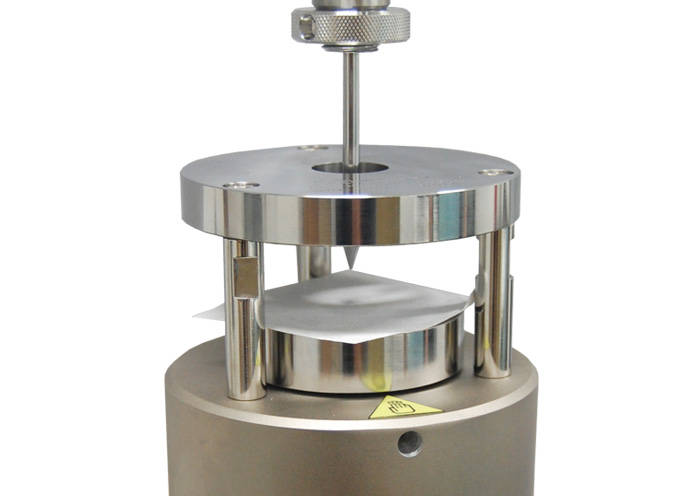
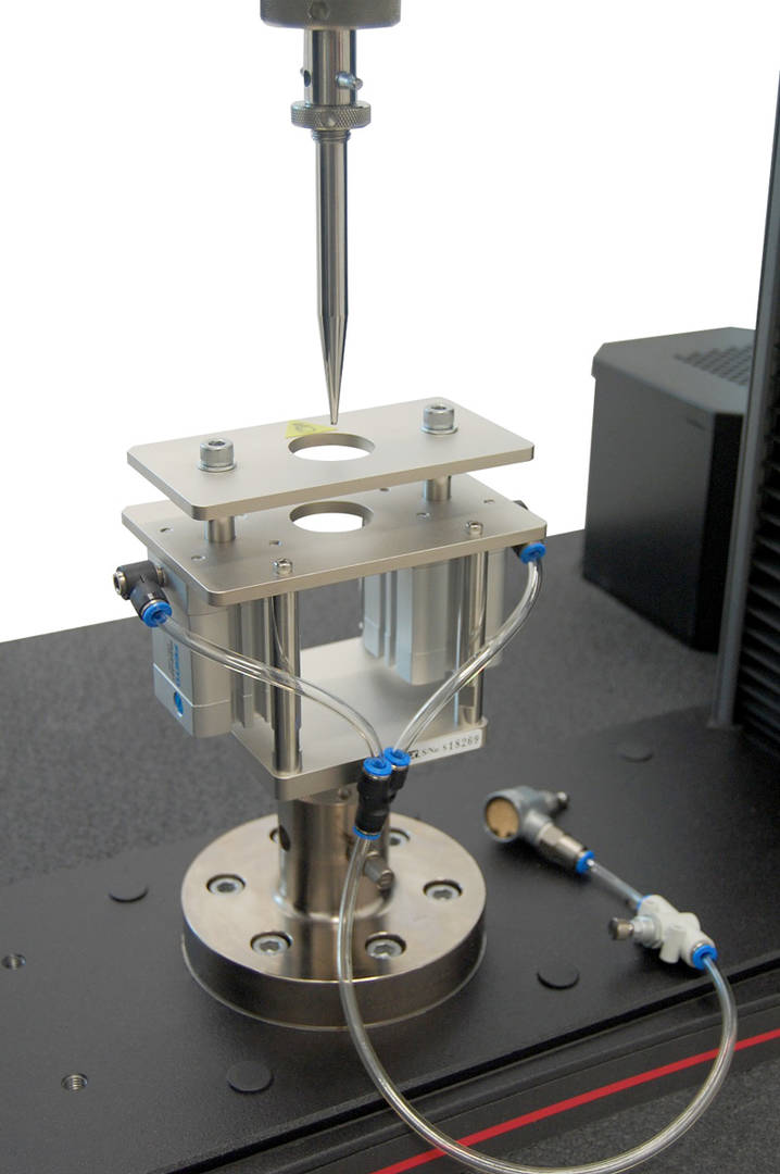
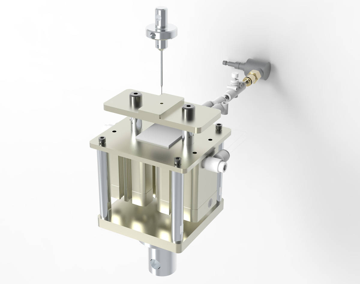
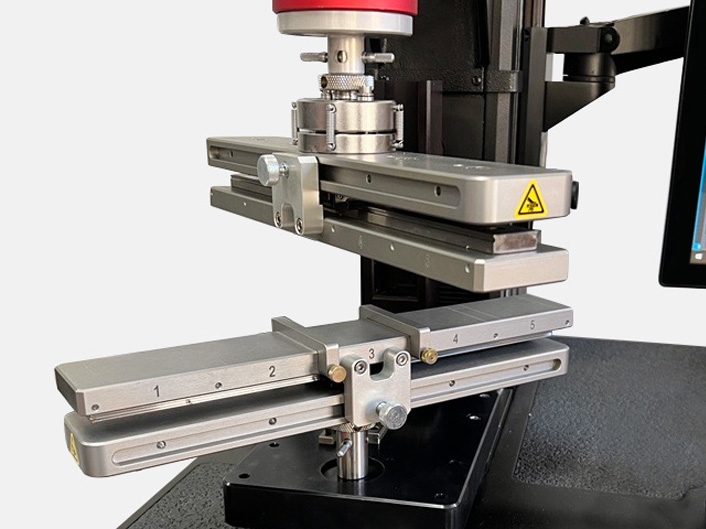
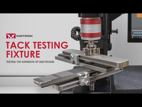
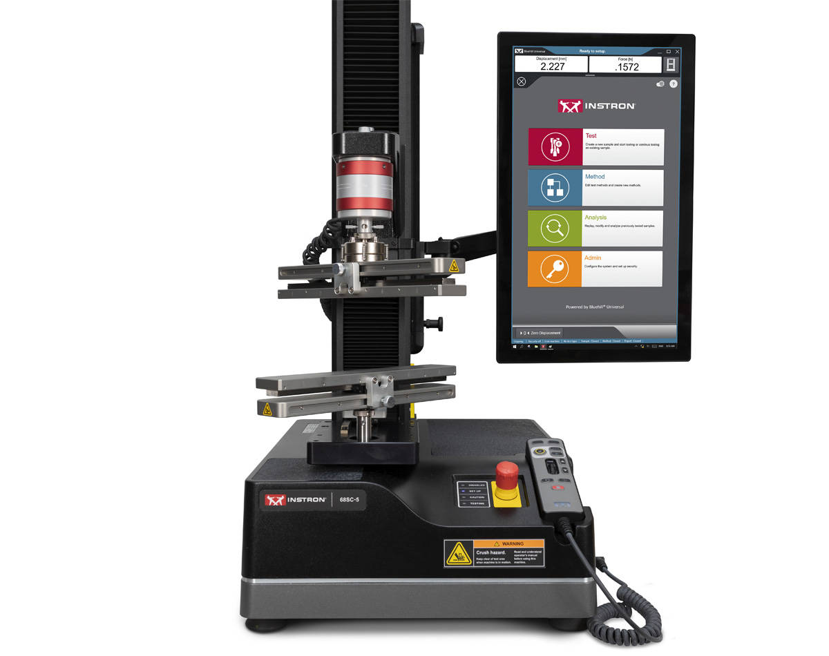
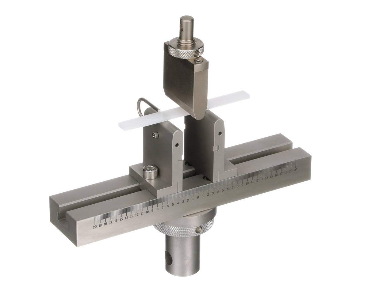
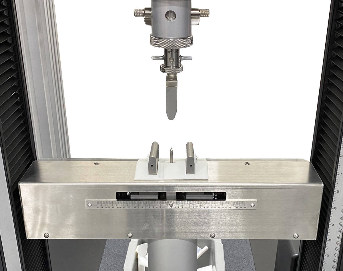
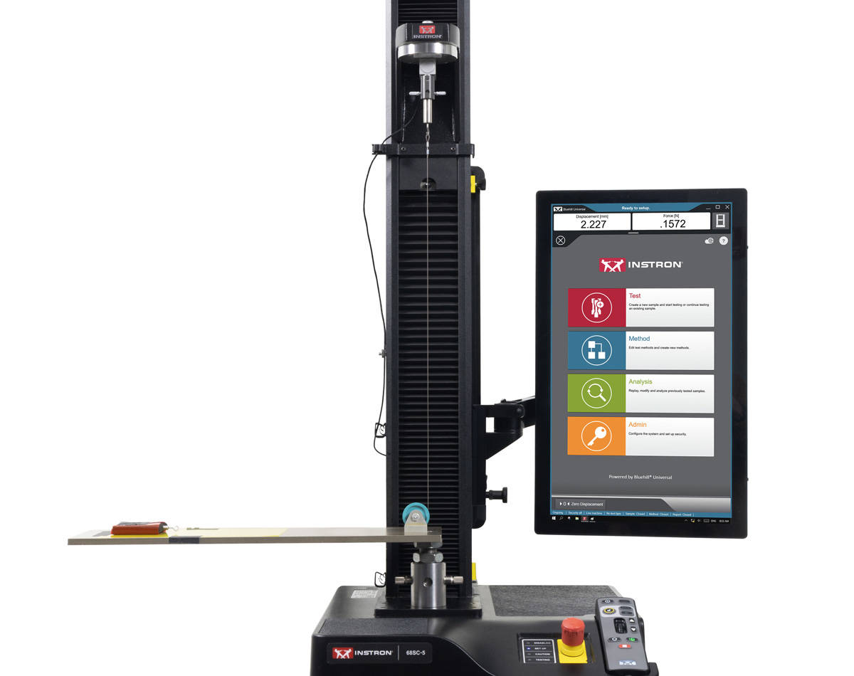

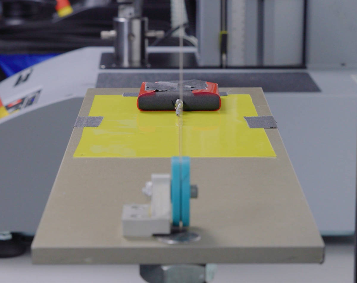
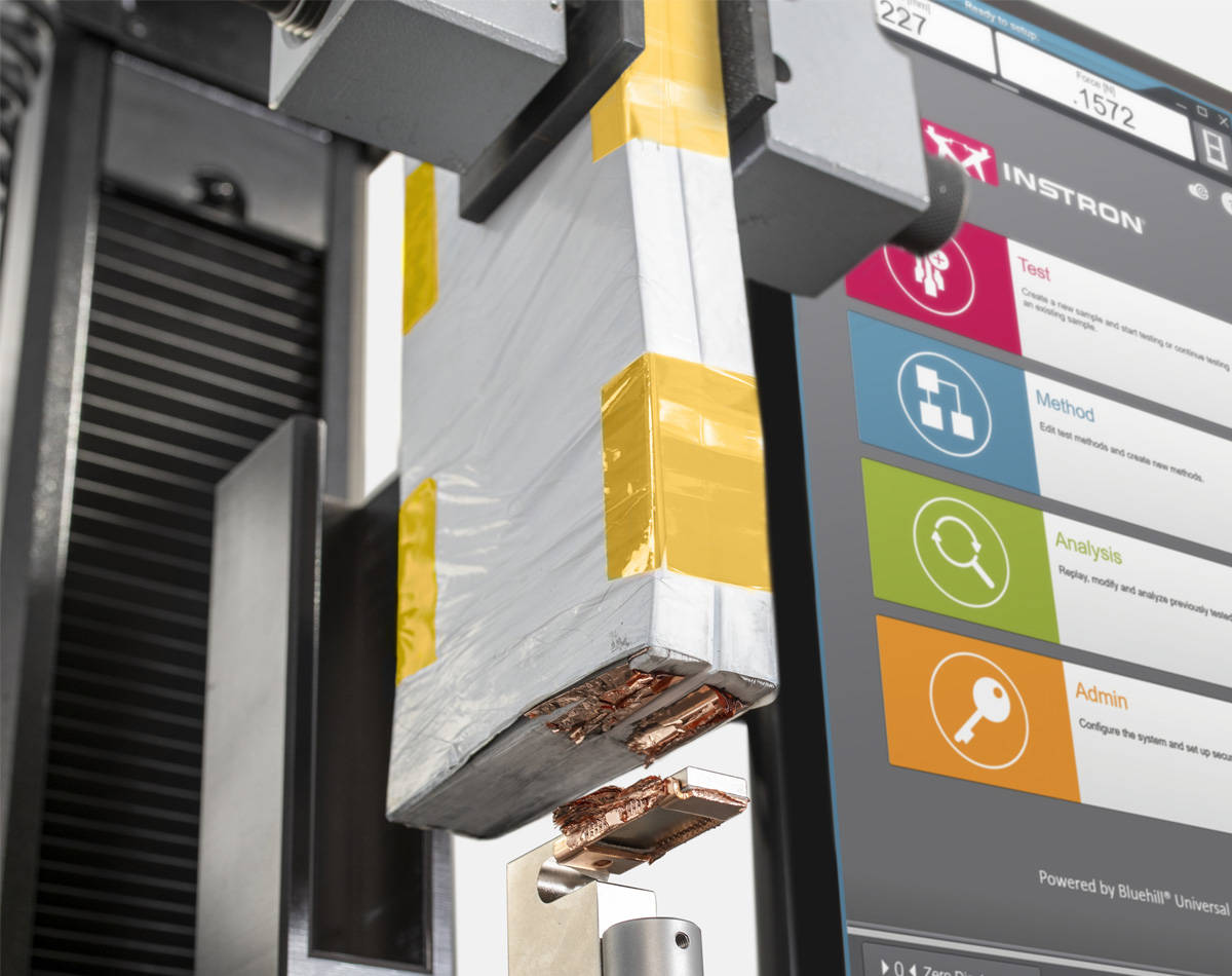
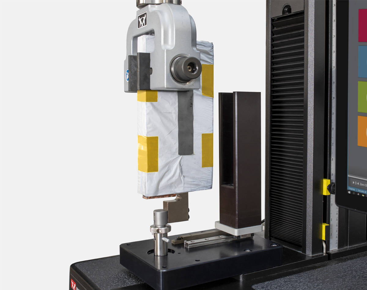

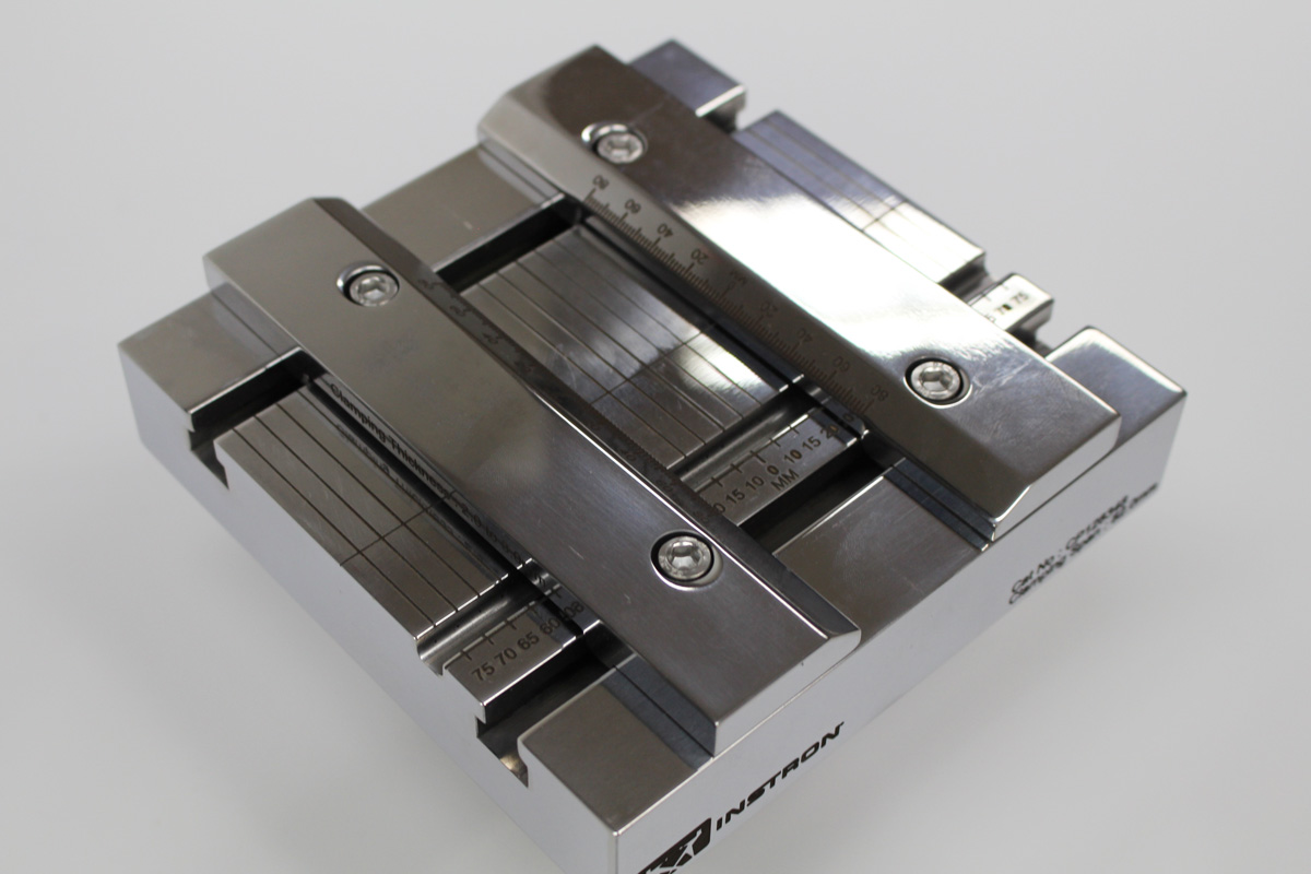
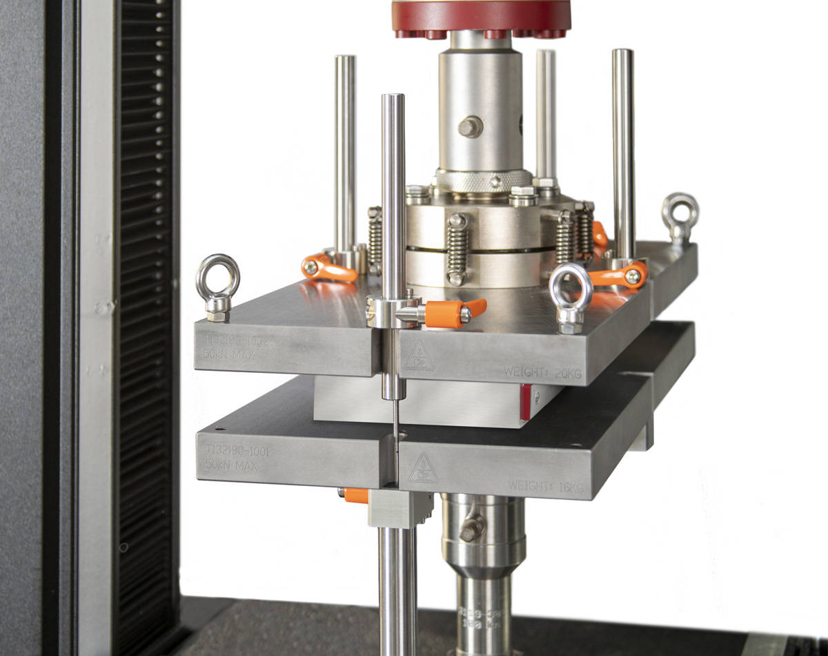

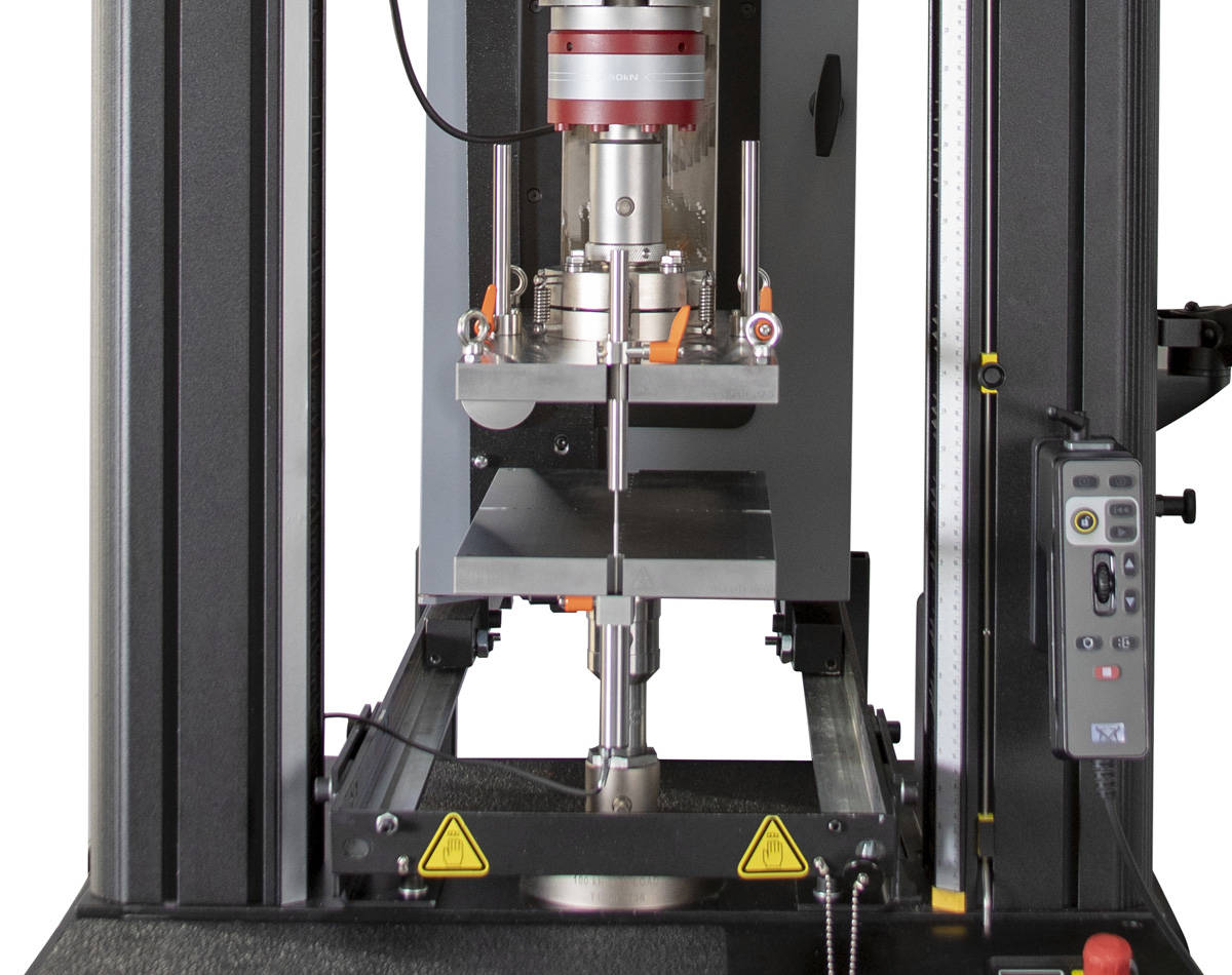


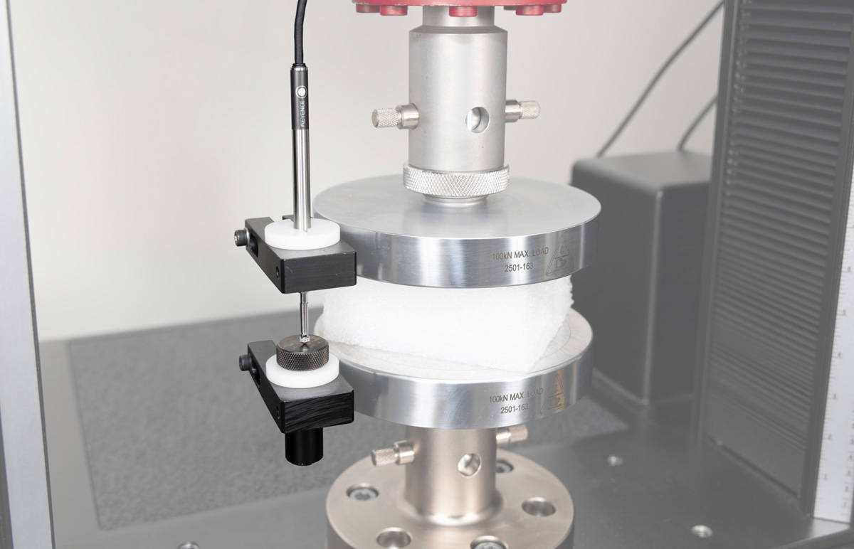
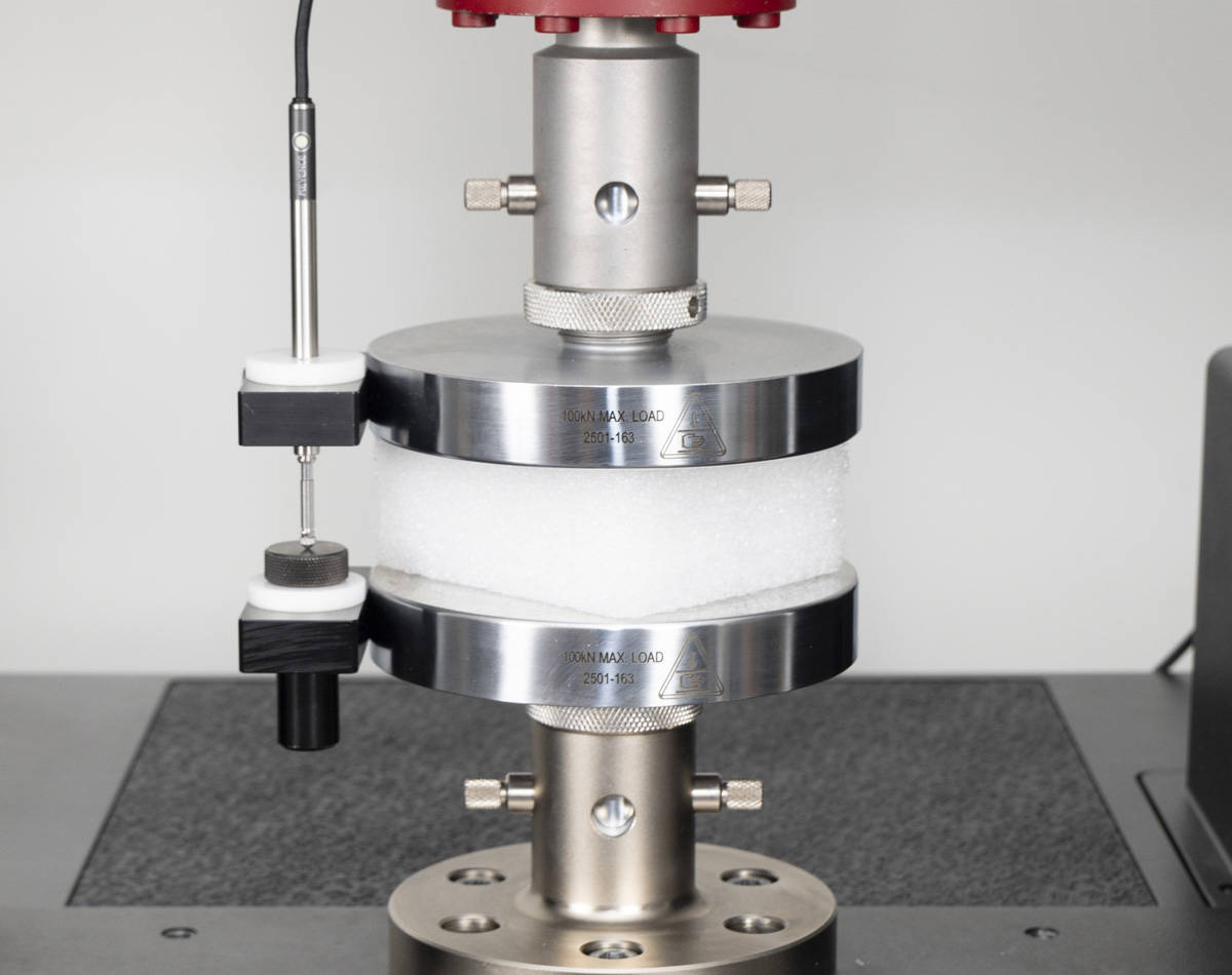
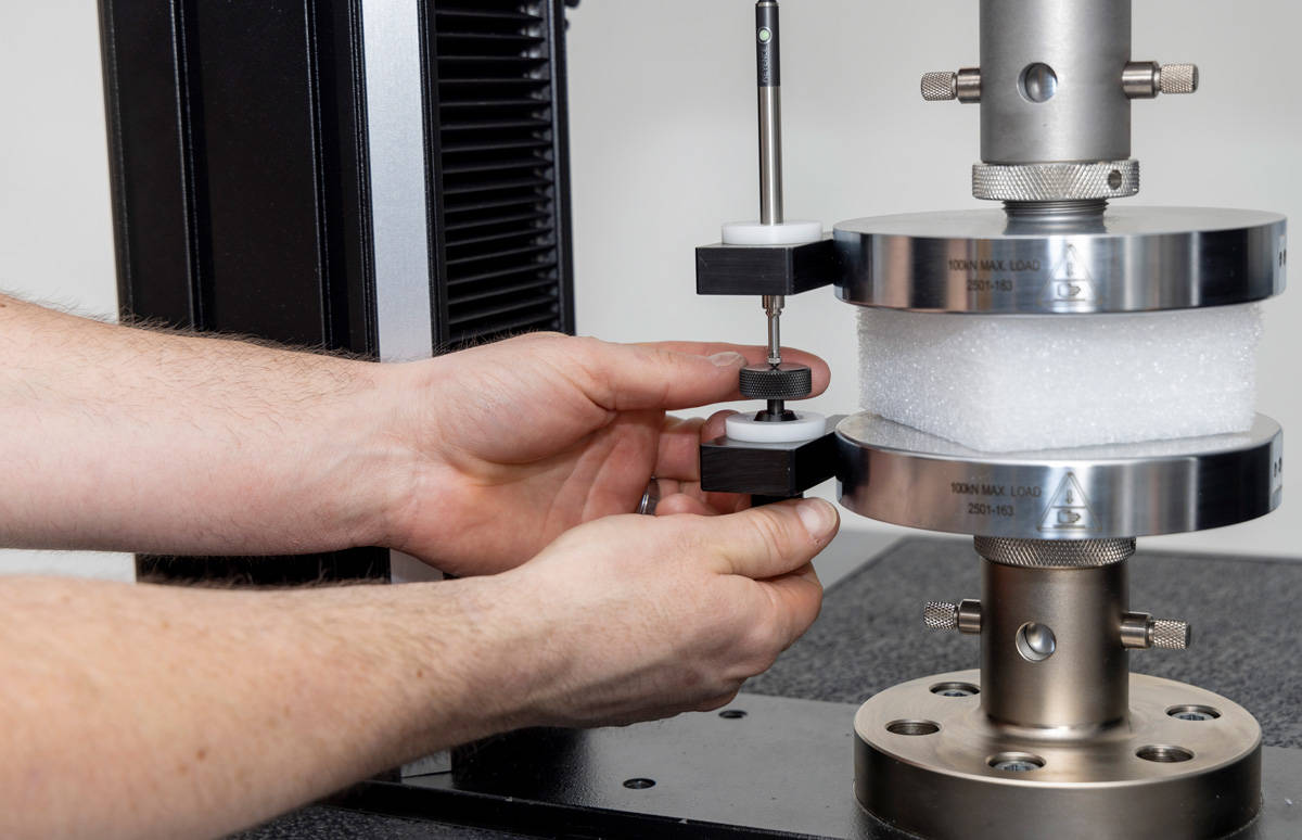


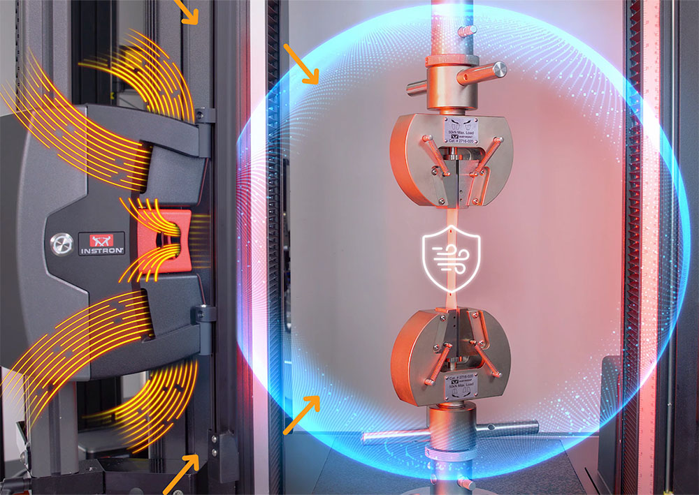
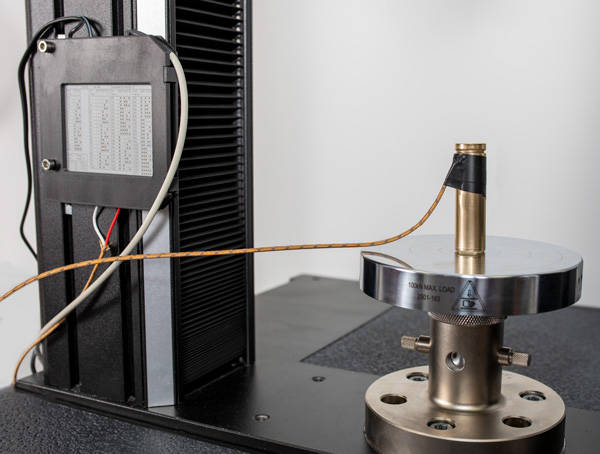

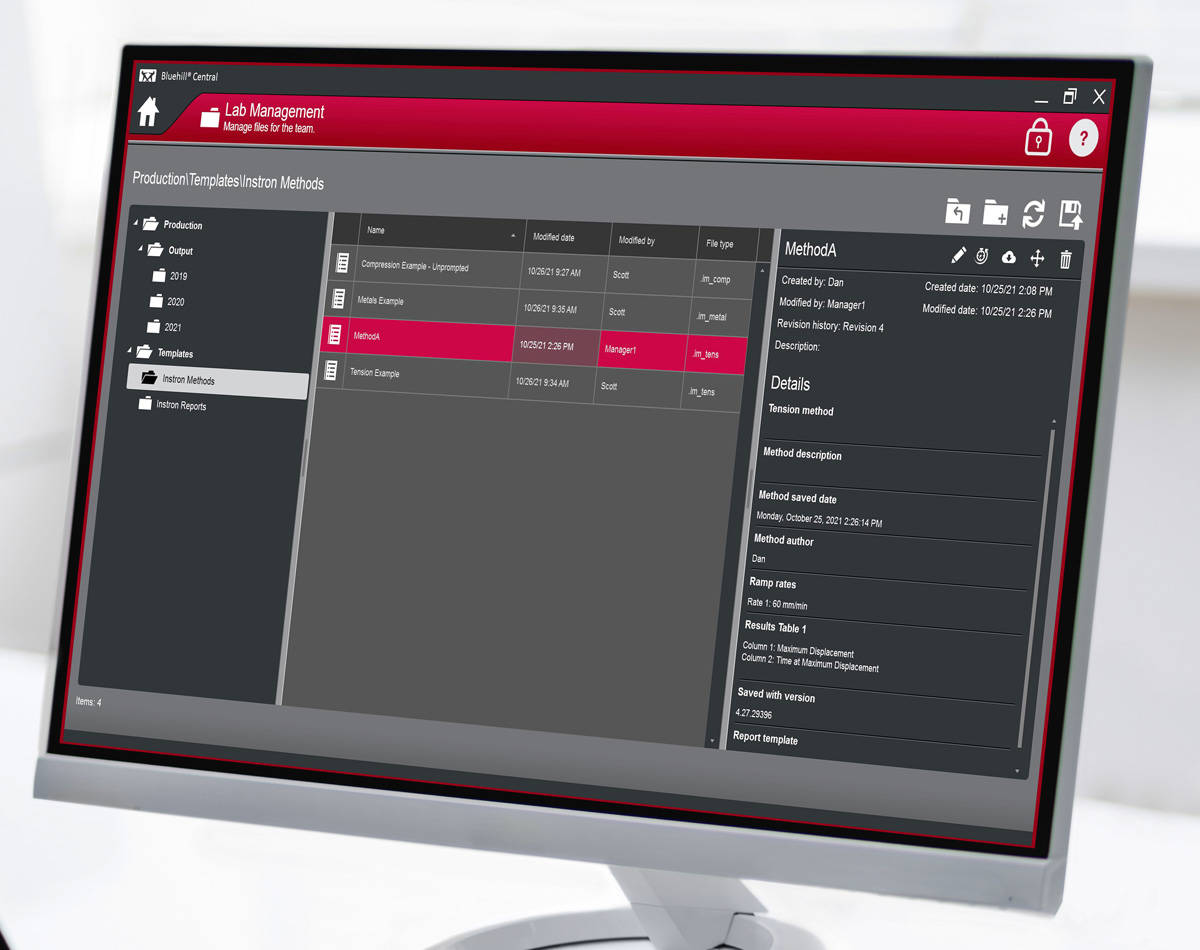


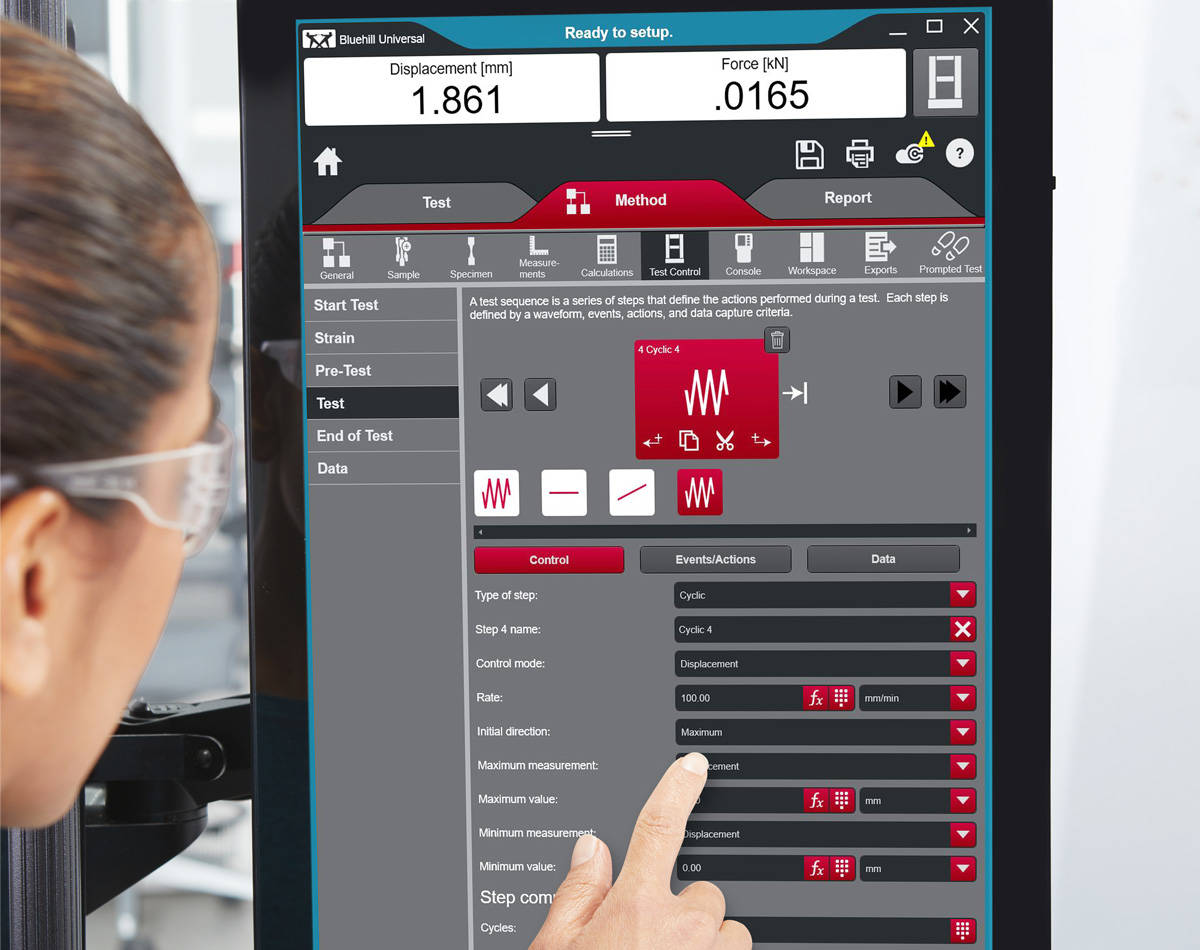


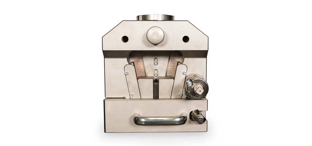


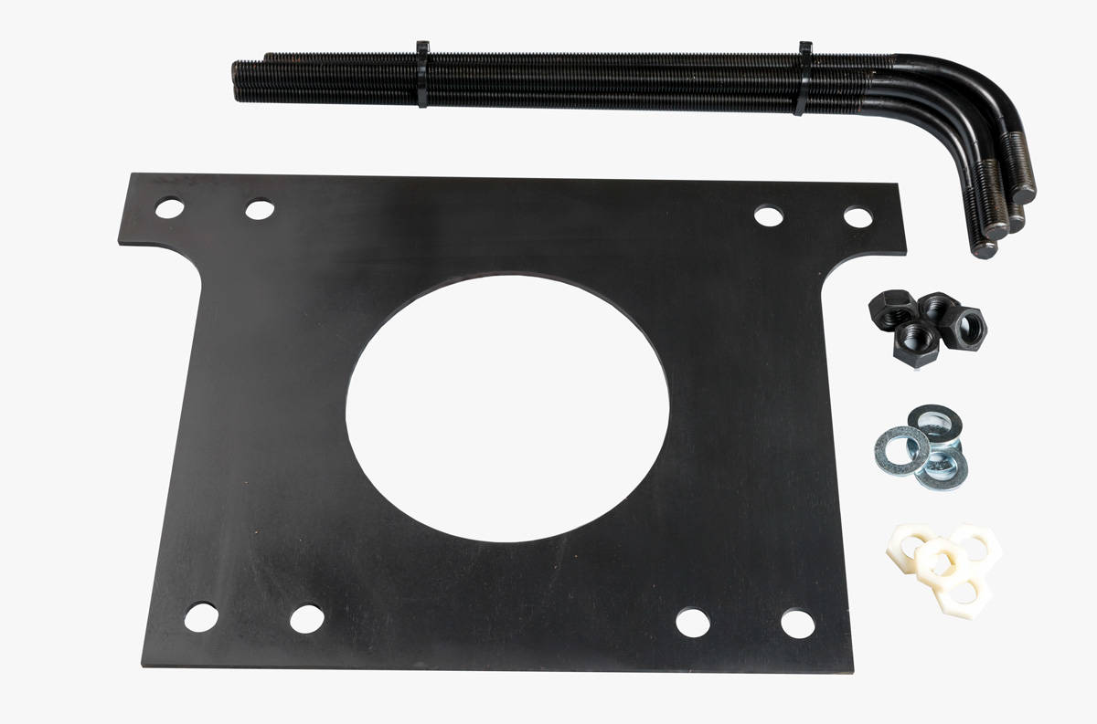
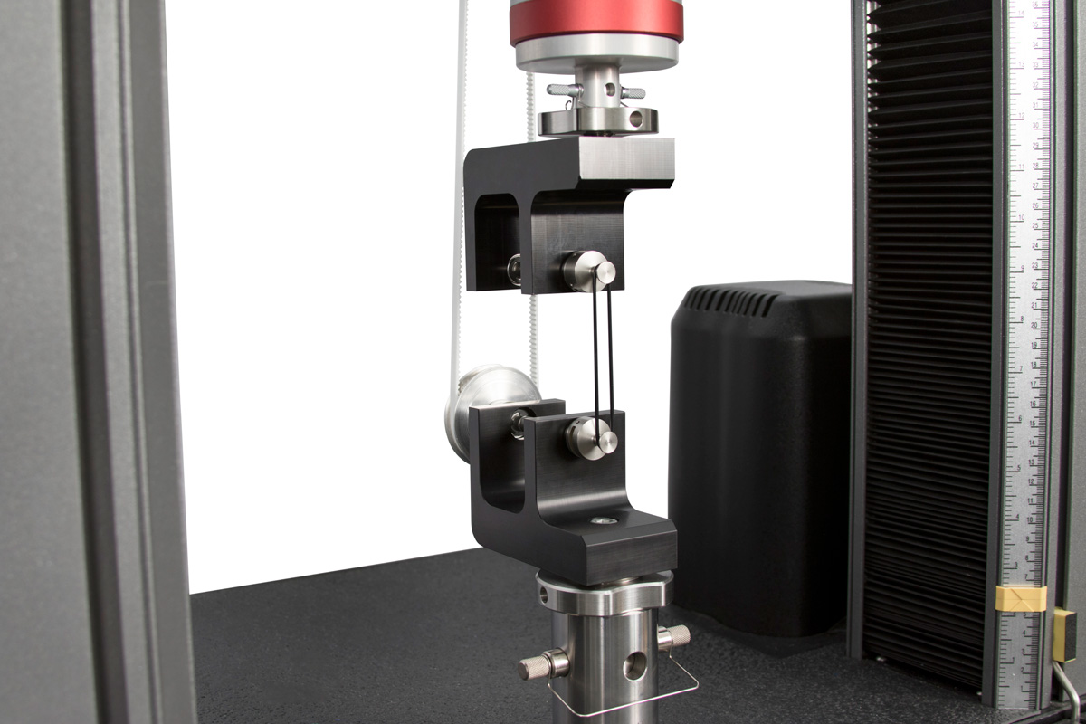
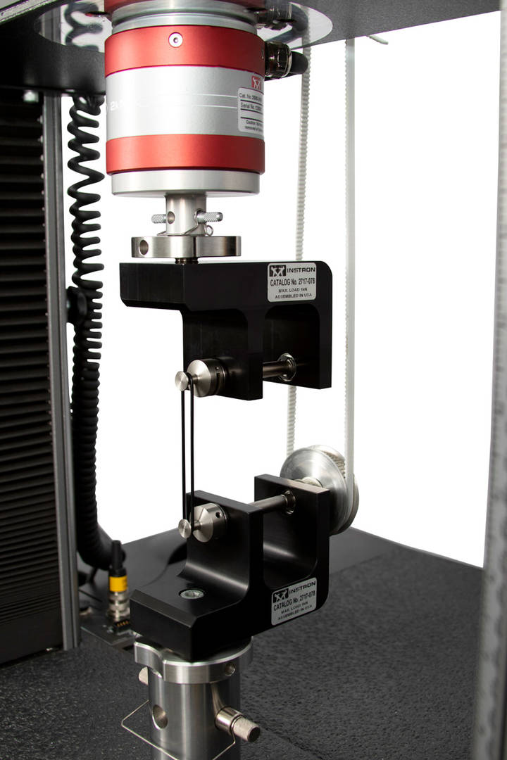
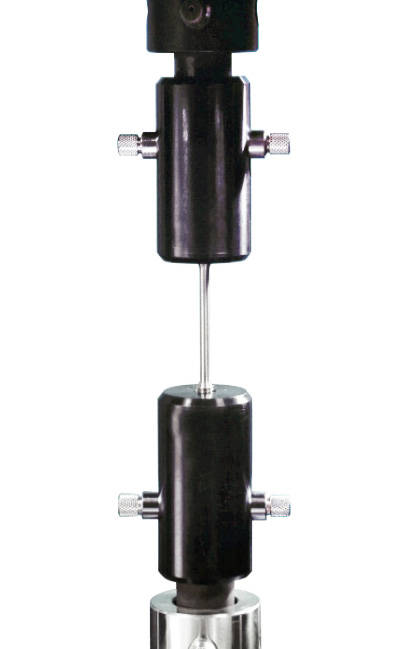
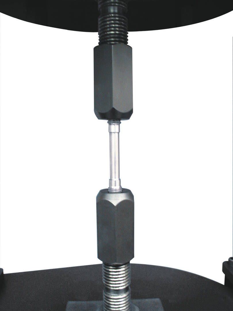

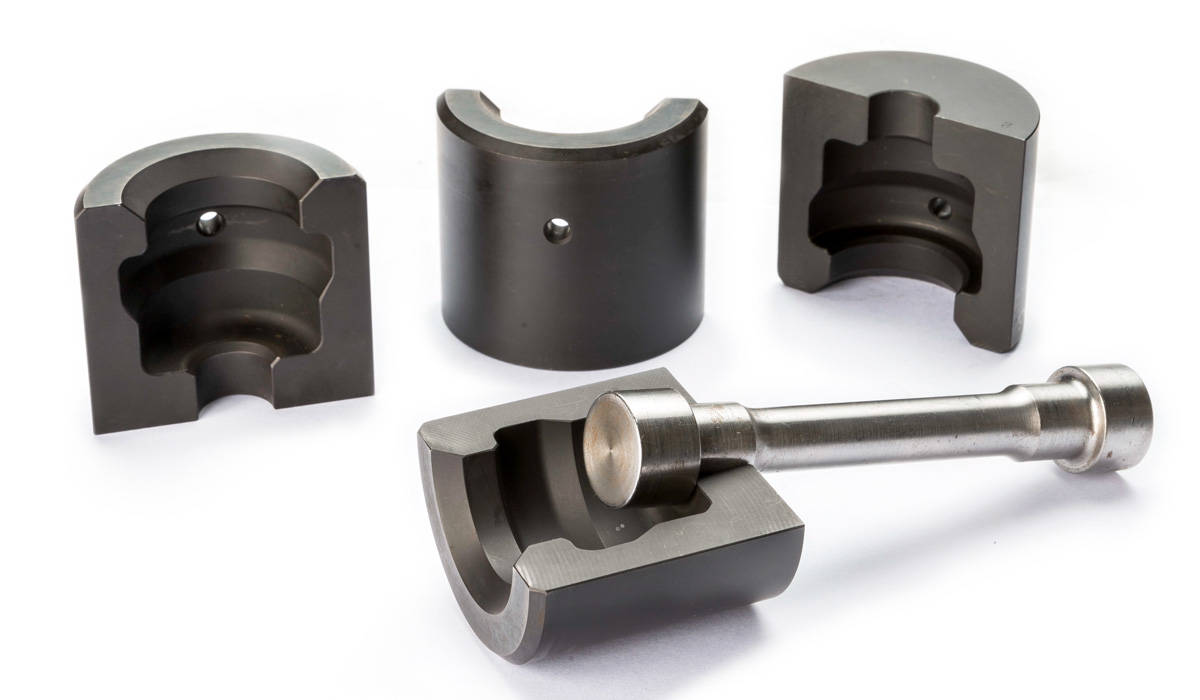
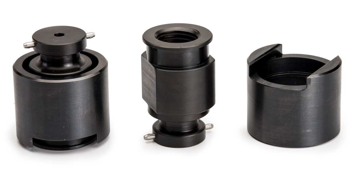
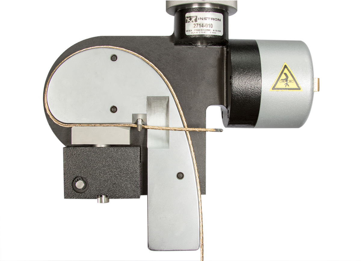
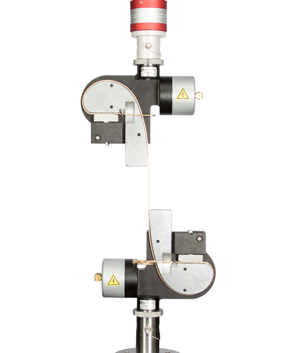
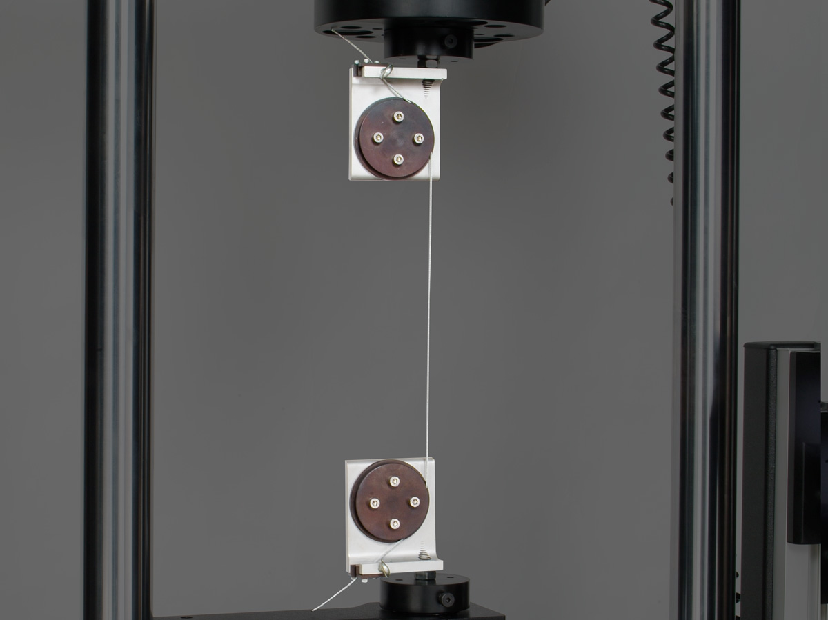
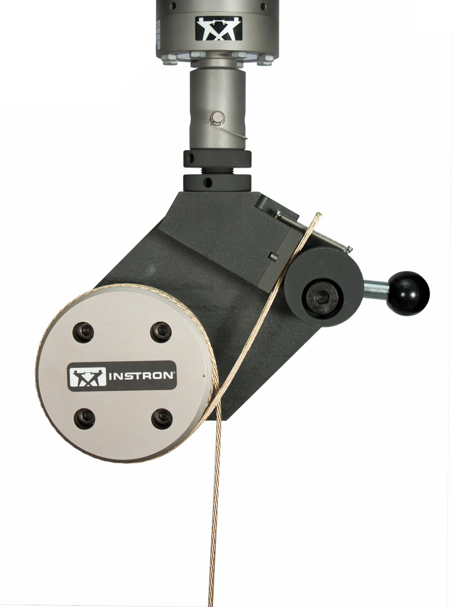
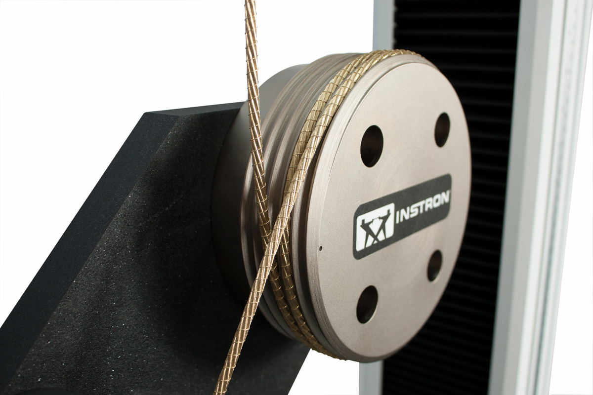

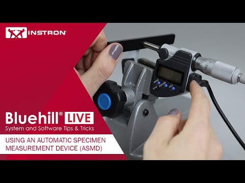


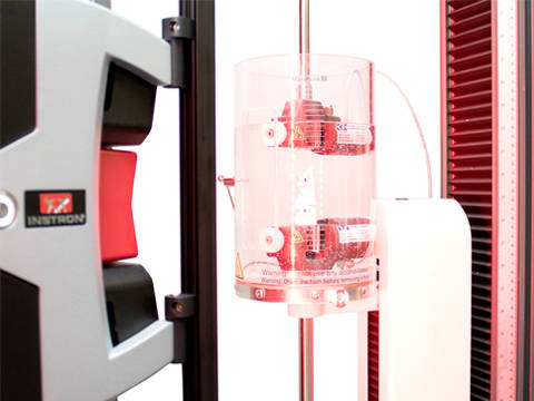

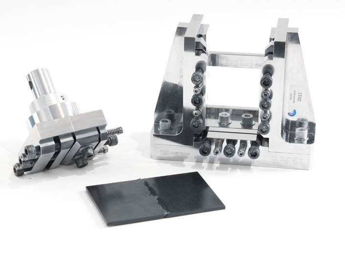
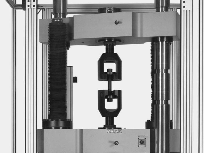
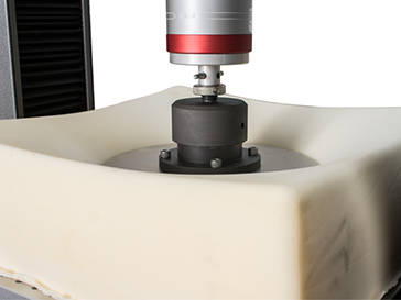
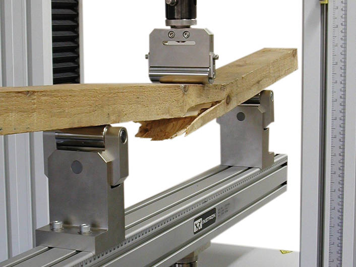
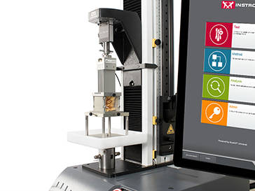
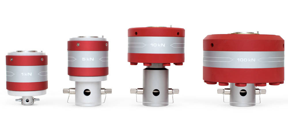
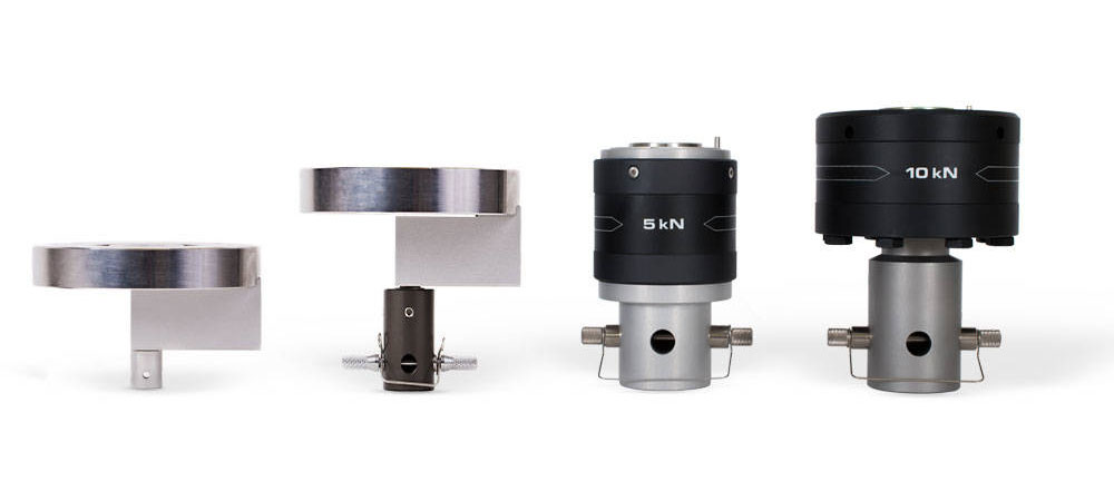


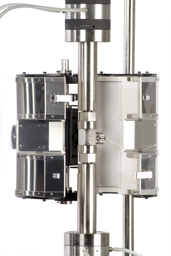

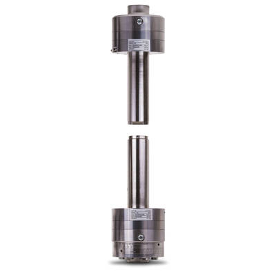
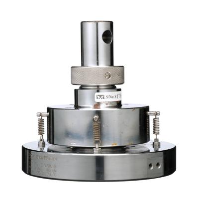
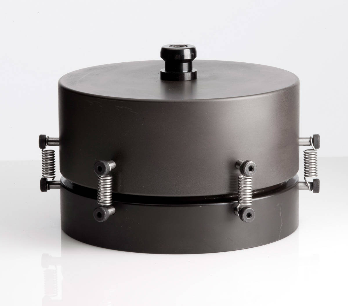
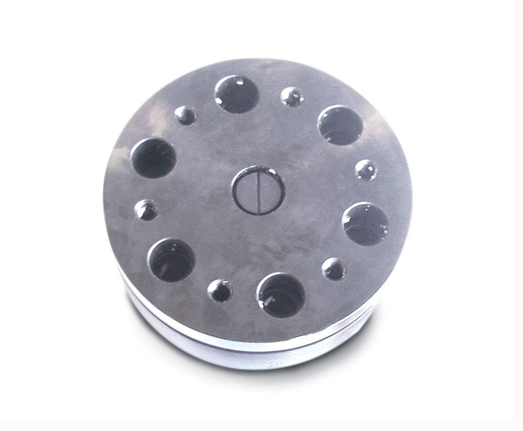
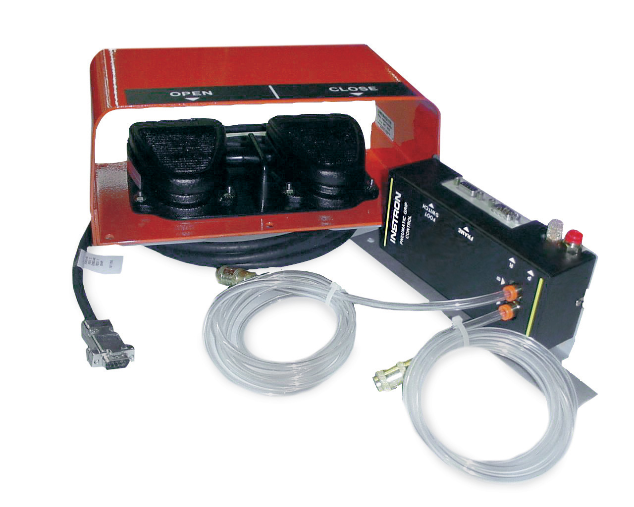
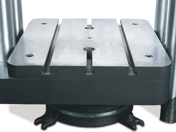
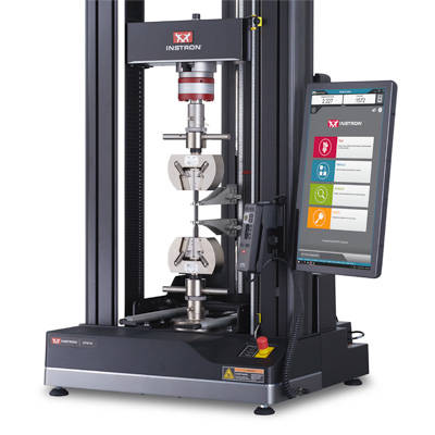
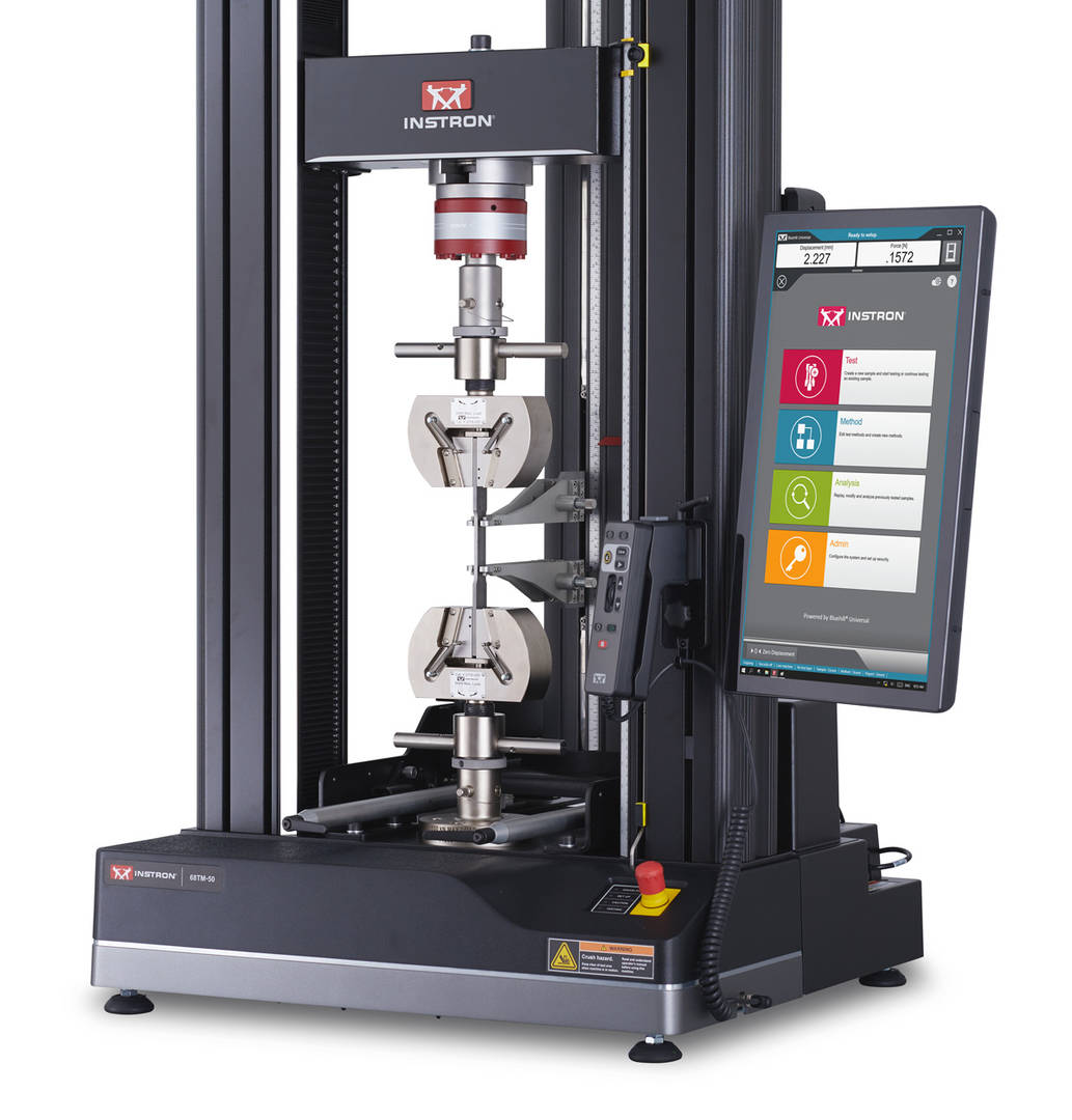


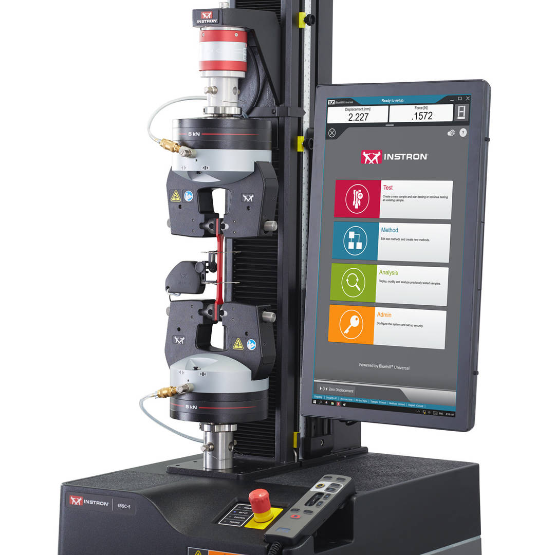


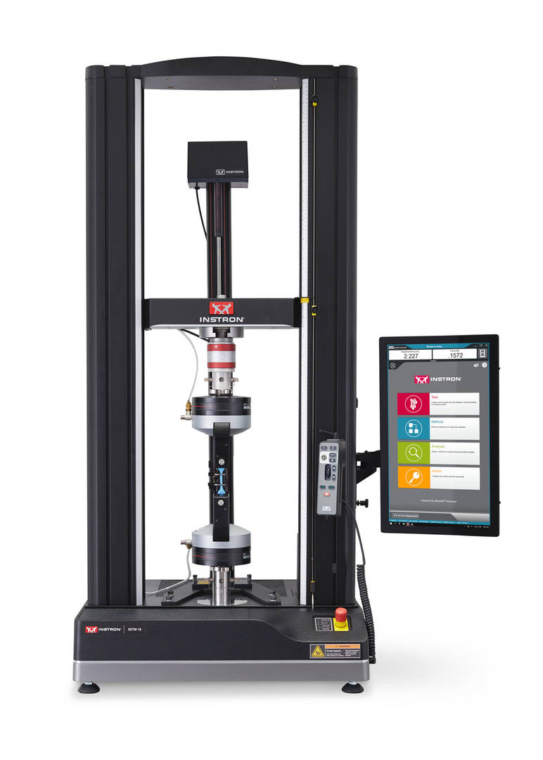


")