Bend Testing of Printed Circuit Boards
AEC-Q200-005A | IPC TM-650 | ASTM F3147-15
The Challenge
Surface mounting and through-hole mounting of electronic packages — including BGAs, QFNs, and CSPs — on a PCB substrate can significantly affect the mechanical reliability of the finished assembly. High-density component layouts and the thermal and mechanical stress of the assembly process increase the risk of warping, cracking, and joint failures between components and the substrate.
When electronic packages are mounted on both sides of a PCB, the mechanical demands on the board and its interconnections are even greater — and the consequences of failure more severe. Standards including AEC-Q200-005A (Automotive Electronics Council), IPC TM-650, and ASTM F3147-15 require testing of finished PCBs to characterize the terminal failure of surface mounted components after bending, flexing, and pulling during assembly. Mechanical failure of populated PCBs in finished products directly affects the electrical performance of the device and presents a significant reliability and warranty risk to OEMs.
Our Solution
Testing Systems - Instron's 6800 Series single column and dual column table model systems are designed for PCB bend testing across a wide range of force capacities. The 3400 Series is also well suited to PCB bend testing applications.
Software - Instron's Bluehill® Universal software provides the calculation tools needed to determine bending stress, flexural strength, and maximum force from the raw test data. Pre-built and customizable test methods simplify setup across different PCB sizes and configurations, and results can be reported in formats that support compliance documentation for AEC-Q200-005A, IPC TM-650, and ASTM F3147-15.
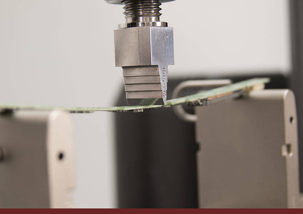
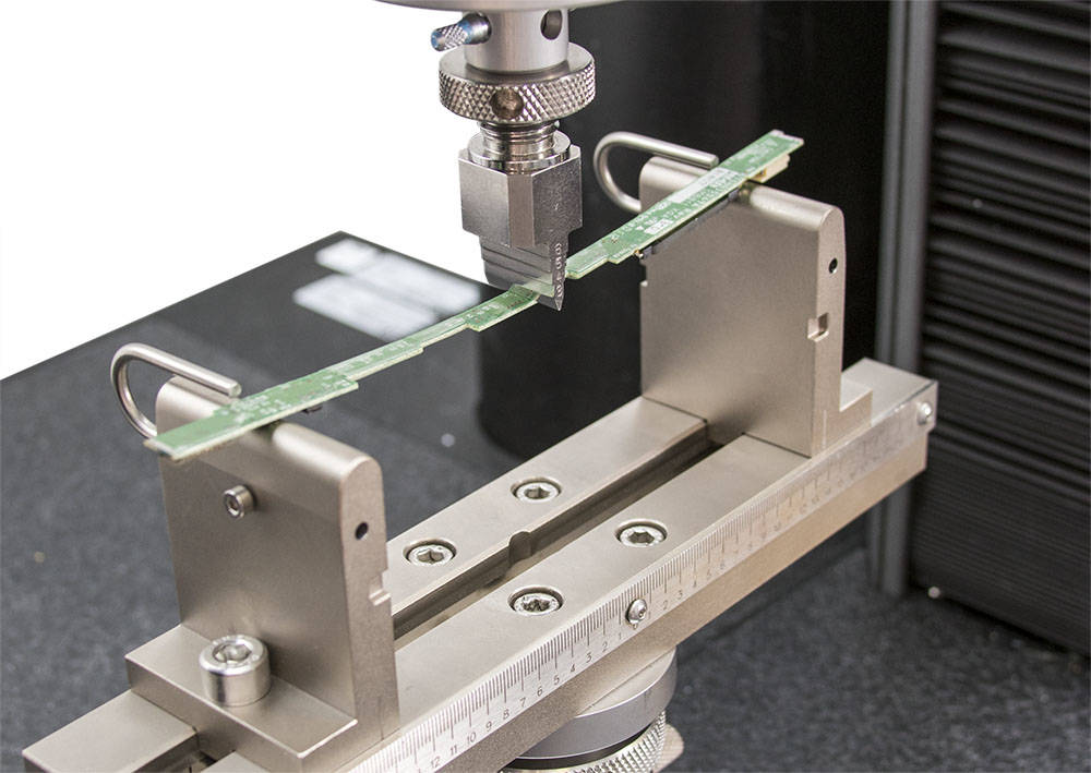
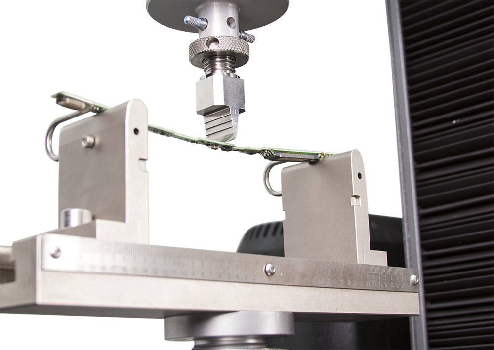
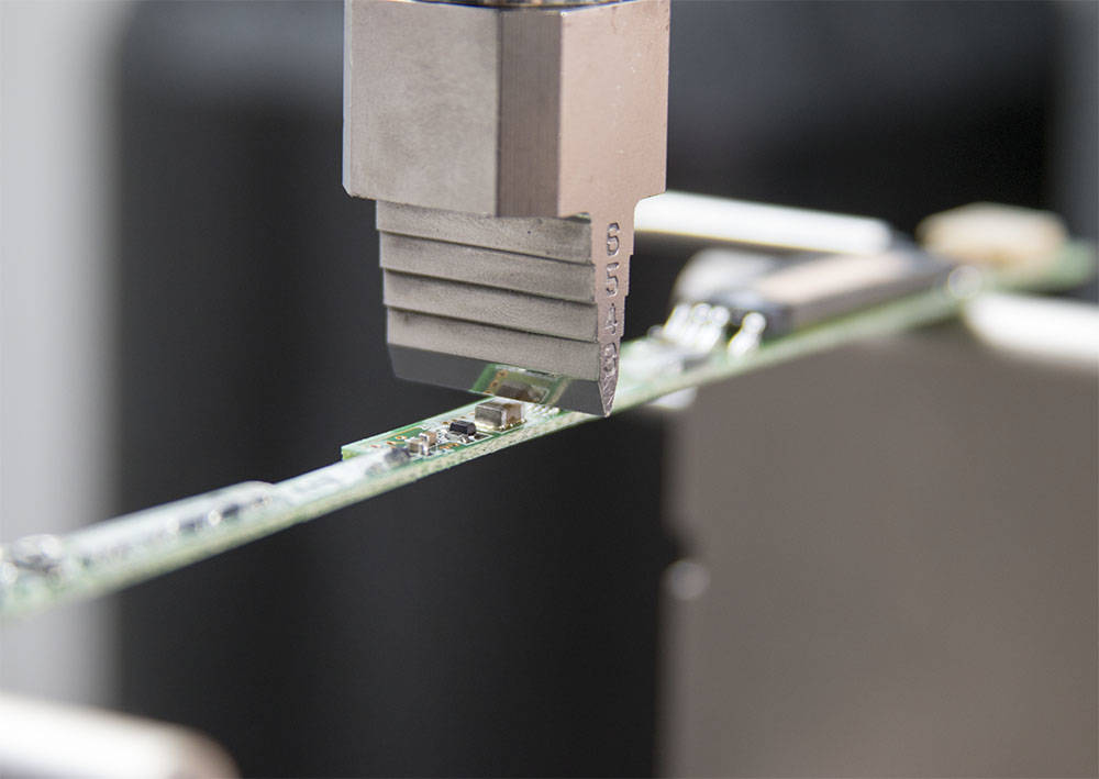
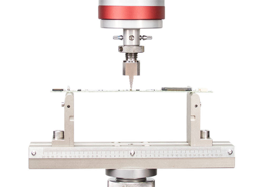
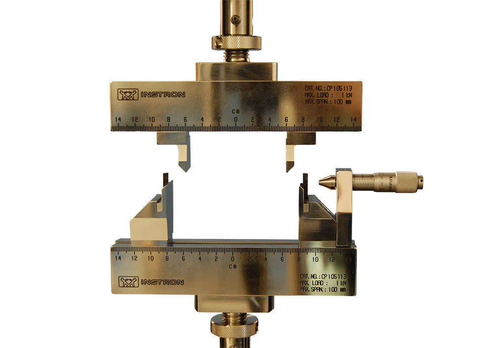
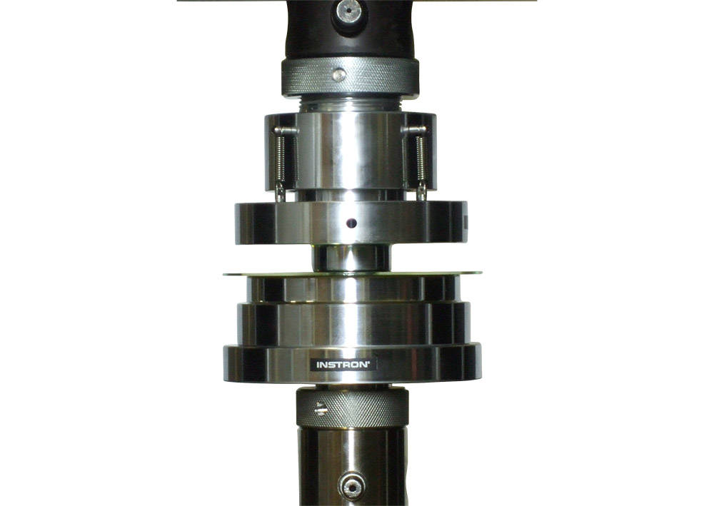
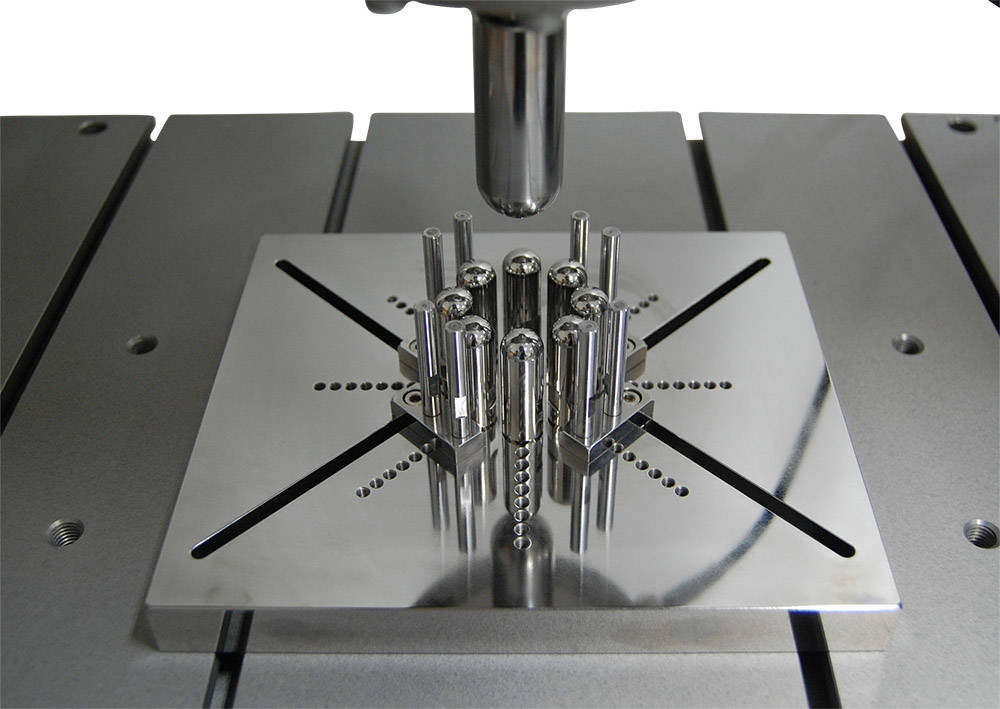
Bend Fixtures - The Instron 2810-400 Series of flex fixtures can be configured with various anvil radii to suit different PCB thicknesses and dimensions. For miniaturized PCBs, micro 3-point and 4-point bend fixtures are available — providing the precision needed for small-scale board testing while maintaining the accurate span control required by the applicable standards.
3-point bend applies concentrated stress at a single point on the board, while 4-point bend distributes the bending moment more uniformly across the span — allowing different failure modes and locations to be evaluated depending on the test objective and standard requirements.

Talk to an Instron Expert.
Whether you are setting up a new PCB bend test program or looking to improve the accuracy and repeatability of an existing one, our team can help you identify the right fixture configuration, span settings, and system setup for your boards and standards.
Contact Our Sales Department.
Please complete the form below and we will be happy to contact you with a response. Our typical response time for an online request is within 1-2 business days. For a faster response, please call +1-800-473-7838.