Torsion Testing of Flexible Circuits and Microelectronic Components

Electronics » Microelectronics

Torsion Testing of Flexible Circuits and Microelectronic Components

IPC TM-650

The Challenge

Because the industry has trended towards the miniaturization of mobile electronic devices, flexible printed circuits (FPC) have become increasingly attractive to OEMs. In addition, the availability of flexible electronic displays allows these products to be flexible or bendable. As these technologies are still relatively new, it is critical to understand the mechanical reliability of these sub-assemblies. Understanding how torsion is applied to FPC panels is important when evaluating component layout patterns under various load conditions.

Our Solution

The Torsion Add-On 3.0 is capable of twisting FPC panels at various degrees of rotation, while pneumatic side action tensile grips can be used to hold FPC panels in the correct position for performing the twisting operations. Bluehill® Universal software offers the ability to create test methods for automating the torsion operation, and for measuring critical results, such as force to break. Cyclic torsion testing can also be set up with Bluehill Universal.

Bend Testing of Printed Circuit Boards

Electronics » Microelectronics

Bend Testing of Printed Circuit Boards

AEC-Q200-005A | IPC TM-650 | ASTM F3147-15

The Challenge

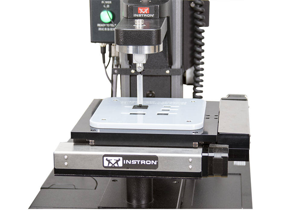
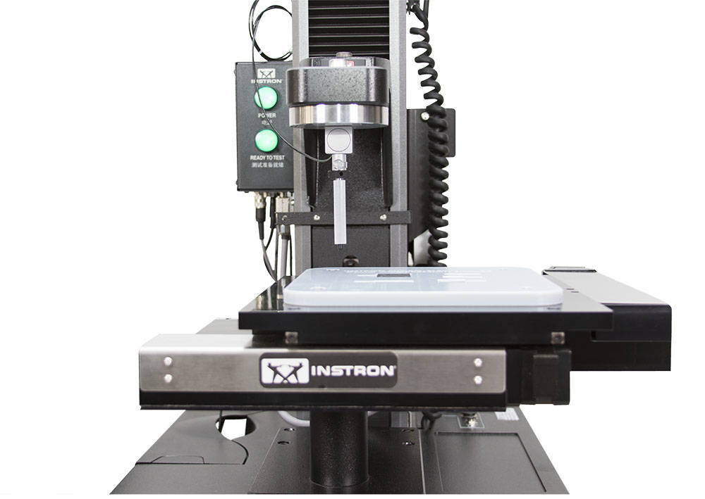
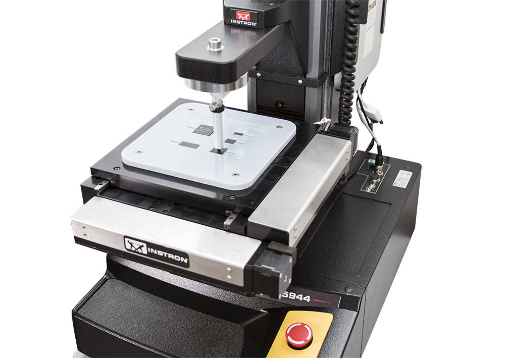
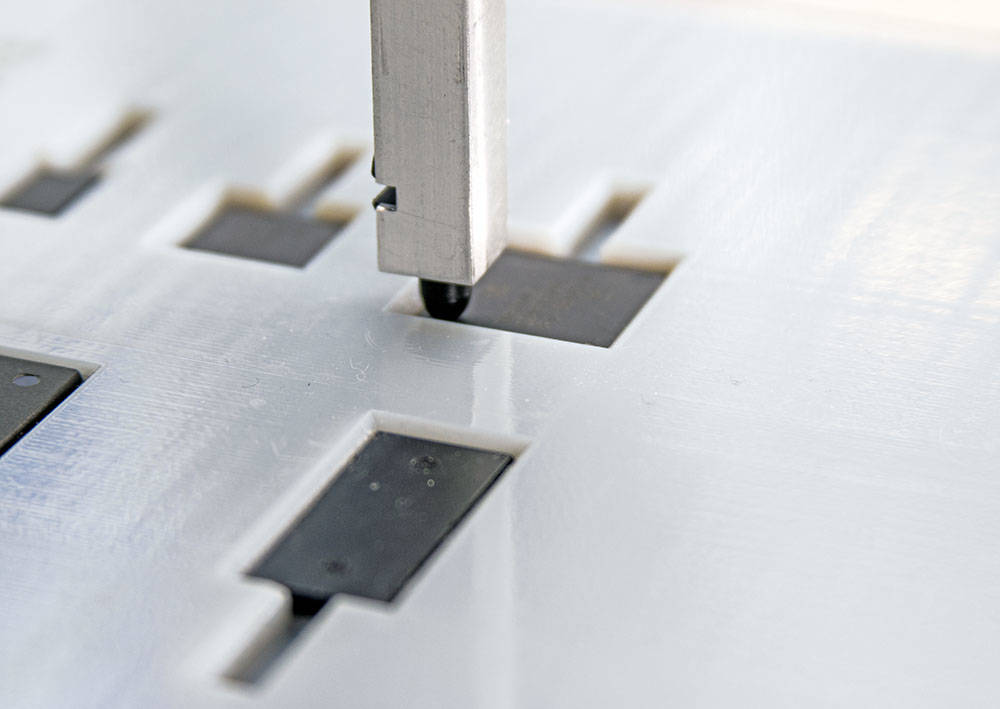
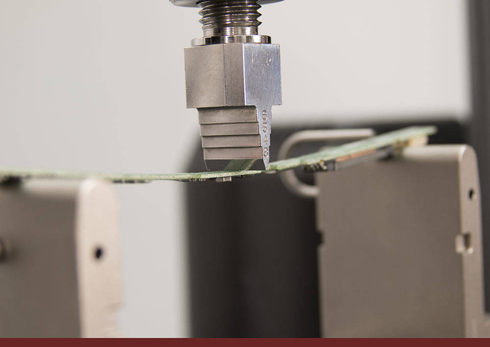
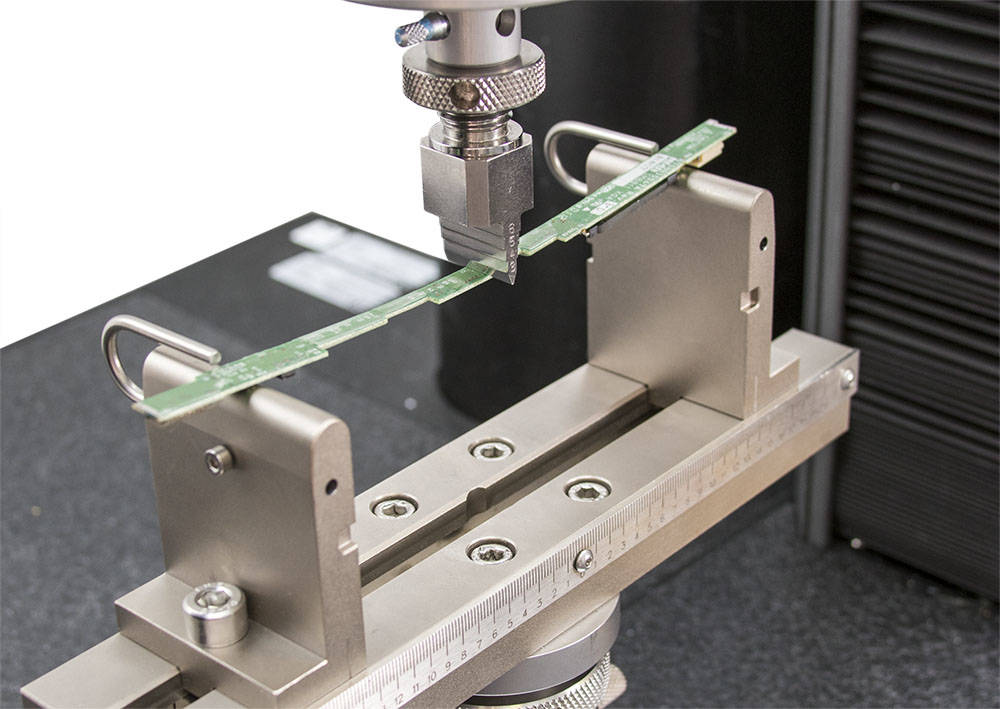
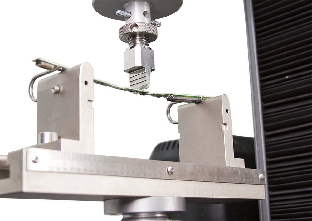
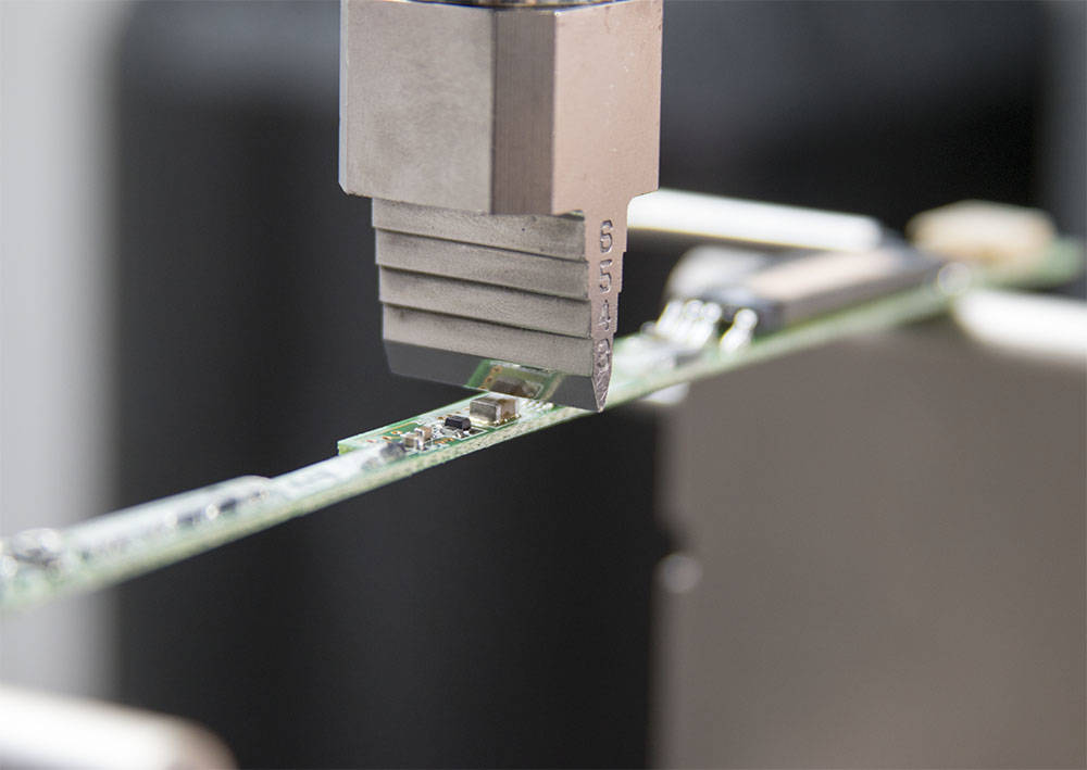
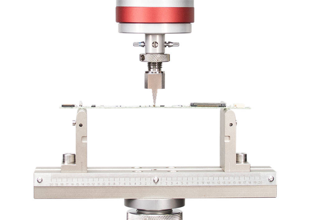
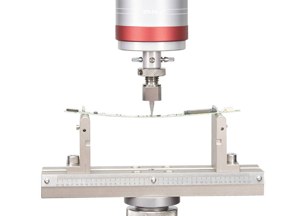
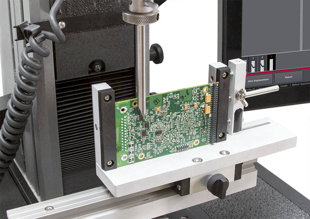
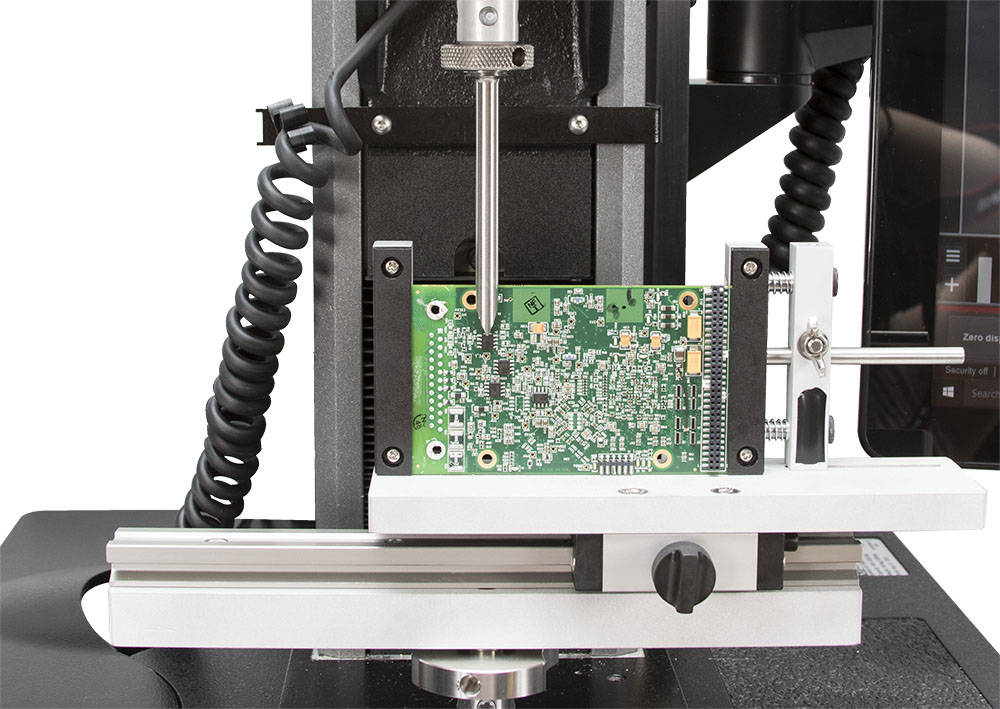
Surface mounting and through-hole mounting of electronic packages, such as BGAs, QFNs, CSPs, etc. on a substrate can impact the mechanical reliability of finished printed circuit board (PCB) goods. With high-density component packaging and complex layouts, PCBs undergo mechanical and thermal stress from the assembly processes, leading to an increased risk of failures, such as warping, cracking, and failure in the joints between the die and the substrate. When electronic packages are mounted on both sides of a PCB, it is even more imperative to understand the mechanical reliability of a finished PCB. Furthermore, requirements driven by standards, such as the Automotive Electronics Council (AEC-Q200-005A) and IPC TM-650, require testing of finished PCBs to understand terminal failure of surface mounted components after they undergo bending, flexing, and pulling during the assembly process. Mechanical failure of these boards in finished products impact the electrical performance of devices where populated PCBs are used, presenting a risk to OEMs.

Our Solution

The Instron® 6800 Series single column and dual column table model systems are designed to conduct bend testing at various force capacities. Additionally, the 2810-400 Series of flex fixtures can be outfitted with various anvil radii. Micro 3-point and 4-point bend fixtures are available for miniaturized PCBs. Bluehill® Universal software offers a wide range of calculations to estimate bending stress, flexural strength, and maximum force.

Teste de cisalhamento de matriz de pacotes eletrônicos


Electronics
»
Microelectronics


Teste de cisalhamento de matriz de pacotes eletrônicos

IPC TM-650 | MIL-STD-883E | AEC-Q200-006A | ASTM F1269-13

O desafio

O teste de cisalhamento de matriz é uma etapa importante ao investigar a confiabilidade mecânica de adesivos condutores que são usados entre a matriz e o substrato. Ao projetar montagens modernas de montagem em superfície, os fabricantes estão constantemente formulando novos adesivos condutores isotrópicos que podem melhorar a resistência ao cisalhamento em relação aos adesivos tradicionais. Além disso, os especialistas estão interessados em compreender a análise de falhas após o cisalhamento da matriz. À medida que as tendências de embalagens de alta densidade e miniaturização de componentes continuam a crescer, os pacotes eletrônicos estão se tornando menores e mais finos. Como resultado, é fundamental compreender o desempenho mecânico desses componentes.

Nossa solução

O teste de cisalhamento de matriz pode ser realizado em um sistema de coluna única ou dupla da Série 6800 com o Dispositivo de cisalhamento de resistência de terminal (CP122690) da Instron, que foi projetado pelo nosso Grupo de Soluções Personalizadas e é usado para segurar uma amostra de placa de circuito impresso (PCB) povoada e componentes de alvo de cisalhamento. O dispositivo consiste em um suporte de PCB ajustável que pode acomodar uma variedade de tamanhos de placa e um trilho linear, permitindo que o operador centralize a sonda no componente de interesse. Uma variedade de sondas pode ser utilizada para testar componentes de diferentes tamanhos. O software Bluehill® Universal pode ser usado para criar métodos de teste, e resultados como a força máxima podem ser medidos. Para uma representação visual do cisalhamento da matriz, o TestCam é oferecido para capturar vídeo em tempo real com o Bluehill Universal.


Teste de Compressão de Pacotes de CI


Electronics
»
Microelectronics


Teste de Compressão de Pacotes de CI

칩의 다점 압축


O desafio

Três tendências intimamente relacionadas na indústria de microeletrônicos são: layouts complexos de placas de circuito impresso (PCB), redução dimensional de pacotes de PCB e empacotamento de alta densidade. A montagem de pacotes eletrônicos, circuitos integrados (CIs) e outros componentes em PCBs introduz estresse mecânico. O empacotamento de alta densidade de componentes tanto na parte superior quanto na inferior de uma PCB cria uma probabilidade aumentada de falhas mecânicas, como trincas ou fraturas. Além disso, os OEMs estão interessados em saber como a aplicação de força altera a tensão ou corrente gerada pelos chips, uma vez que os materiais usados para fabricar esses chips e suas formas evoluem constantemente ao longo do tempo.

Nossa Solução

Os sistemas de coluna simples e dupla da ® Série 6800 Instron, juntamente com uma Mesa XY Automatizada, são configurados para realizar testes de microcompressão em múltiplos pontos de um chip ou componente. Dispositivos desenvolvidos por nosso Grupo de Soluções Personalizadas podem fixar esses componentes nas posições adequadas para conduzir o teste com precisão. Como os testes de microcompressão envolvem a medição de deslocamento ou deflexão em mícrons, rotinas podem ser executadas para eliminar qualquer complacência do sistema ou variação da máquina, célula de carga e do dispositivo. Diferentes estilos de sondas estão disponíveis e podem ser desenvolvidos para realizar testes de compressão baseados em pontos.

Platôs de microcompressão estão disponíveis para conduzir a compressão de todo o pacote ou chip simultaneamente. Dispositivos de medição externos, como o Dispositivo de Deslocamento de Platô LVDT, podem ser usados para realizar medições de estilo de contato, e o Extensômetro de Vídeo Avançado AVE3 pode ser usado para realizar medições de deflexão sem contato em mícrons. O software Bluehill® Universal da Instron é usado para configurar métodos de teste para uma mesa XY ou platôs de microcompressão. Usando canais de deformação externos, resultados gráficos sobre tensão e resistência à força correspondente podem ser apresentados no software.

Solder Ball Compression Test

Electronics » Microelectronics

Solder Ball Compression Test

IPC TM-650

The Challenge

Solder paste manufacturers and electronics packaging experts are constantly formulating new compositions of solder alloys and flux materials to address assembly challenges. Type 6 solder powder, with a particle size of 10 µm and below, is preferred over type 4 and type 5 solder pastes for the assembly of 0201s chip components. Ball grid array packages (BGA) that are attached on the substrate using solder bumps on the bottom of the package are trending towards smaller size solder bumps. As a result, it is important to perform mechanical testing on the solder bumps, or solder balls, in order to understand the maximum load sustainable before failure. One effective way to test these solder balls is through compression. By applying a compressive load to a single solder ball, maximum force can be estimated before the ball cracks to failure. This helps in characterizing the bump strength of solder for package assemblies.

Our Solution

The Instron® 6800 Series systems are ideal for conducting this micro-precision compression test. Depending on the force required to break, either a single or a dual column system can be used. Custom pin type probes of various dimensions are available to perform accurate compression tests on the solder ball. A multitude of clamping solutions are offered for accurate clamping and positioning of package assemblies for conducting this test. Instron’s AT2 automated XY stage testing System offer an automated solution for performing compression tests on multiple solder balls in a single test run. The TestCam module in Bluehill® Universal software can be used for real-time live feedback of the compression test, allowing for a visual review of the bump compression for qualitative analysis. In cases where you need to introduce a high temperature before performing the test, custom heating stages are available, allowing you to heat the package or the substrate prior to compression. 

Stud Pull Test for Electronic Packages

Electronics » Microelectronics

Stud Pull Test for Electronic Packages

The Challenge

A typical surface mount assembly involves mounting electronic packages onto the printed circuit board (PCB). This assembly requires bonding of a chip or die onto the PCB using solder paste and other adhesive materials. For example, the assembly of flip chips, ball grid arrays (BGA), and chip-scale packages (CSP) require you to apply the process of underfill for the bonding between the die and the substrate. As part of the design and mechanical validation, OEMs look to perform tests that measure the bond strength of the adhesives in a package assembly at various operating conditions. One such critical technique is the stud pull test for packages of various dimensions.

Our Solution

Instron® offers an easy to use stud pull fixture with a specimen preparation fixture for running the test at ambient and high temperatures. The specimen preparation fixture allows the operator to bond the studs on the die package using a high strength adhesive. The fixture applies a constant force, enabling correct alignment, which is highly critical to the test. In addition to the preparation fixture, the stud pull fixture has upper and lower fittings with self-aligning swivels at both sections. This allows for accurate alignment of the studs in parallel to the frame, or perpendicular to the cross-head. High temperature chambers are also offered to perform this test. Stud sets are designed in various sizes, ranging from 2 mm to 50 mm, to fit a range of die package dimensions.

Bend Test of Electronic Packages

Electronics » Microelectronics

Bend Test of Electronic Packages

SEMI G69-0996 | ASTM D790 | ASTM D6272 | IPC TM-650 | JEDEC 9702 | MIL STD 883 | SEMI G86-0303

The Challenge

Understanding the mechanical reliability of microelectronic components and packages is a critical step towards design validation.  With high density packaging, components are getting smaller and thinner so they can be used on the printed circuit boards (PCBs) of hand-held devices. Furthermore, new materials are being introduced, such as the addition of layers on electronic packages, which requires validation of the material’s strength. During new product development, OEMs are required to know the mechanical stress induced on various electronic packages, as they are subjected to warping from the assembly process of PCBs on the top and bottom of the substrate. New innovations in electronic packages, such as chip-on-film, stacked multi-layered packages, etc. require a thorough understanding of mechanical failure.

Our Solution

The Instron® micro bend fixtures are designed to perform bend testing on small scaled electronic packages, and other microelectronic components. The micro 3-point and 4-point bend fixtures are used to apply stress at local regions, or throughout the package. Using these fixtures, users can determine the load at which the packages undergo failure, such as cracking, delamination of layers, fatigue, etc. Bend fixtures are available with various anvil radii based on package dimensions. Variable span adjustments on the lower anvil are available using a micrometer screw gauge to precisely set the span length. Bluehill® Universal software can be used to easily set up test methods and to perform the bend tests on different sized components. In cases where flexure displacement is a required measurement, a compliance correction routine can be performed to eliminate any system compliance that can affect the results. 

Tensile Testing of Copper Clad Laminates (CCL)

Electronics » Microelectronics

Tensile Testing of Copper Clad Laminates (CCL)

IPC TM-650 | ASTM D5109-12

The Challenge

Laminates are basic materials used to mechanically support electronic components and to interconnect them electrically. Copper clad laminates (CCL) are comprised of multiple layers of copper foils and reinforcing materials that are used between the foils. In the printed circuit board (PCB) manufacturing process, CCLs are used as a base material for electrical conductivity and physical performance, such as dimensional stability, punching quality, peel strength, bending strength, heat resistance, etc. As new reinforced materials (i.e. fiber-glass cloth, asbestos sheet, and paper) and different types of resins (i.e. phenolic, epoxy, and polyimide) are used, it is critical to perform mechanical testing under various conditions in order to understand the total strength of particular laminates. Reinforced materials used in combination with resins are designed to have excellent heat resistance, which prevents thermal stress on the PCB during the assembly process. Therefore, manufacturers are particularly interested in understanding the mechanical performance of CCLs in high temperature conditions, with the expectation of a similar performance under ambient conditions.

Our Solution

Instron® 6800 Series single column and dual column systems can perform tensile tests on CCL materials, and can be equipped with a set of grips to fit the dimensions of the CCL being tested. When performing strain measurements, contact and non-contact style strain devices are available. The 2630 Series and W-6820 Series axial clip-on extensometers are simple contact-style strain measurement devices. Non-contact video extensometers, such as the AVE3 Advanced Video Extensometer, are more advanced and offer higher accuracy for strain measurement.

To perform tensile tests at non-ambient temperatures, the 3119-600 Series environmental chambers are capable of achieving temperatures that can range from -150O C to +350O C. For high temperature conditions, corresponding grips and contact-style extensometers are also available.

Bluehill® Universal software offers the ability to easily set up test methods and run tests at various environmental conditions. Results such as strain and tensile strength can be calculated from the software. The QuickTest feature allows the user to set up and quickly run a tensile test in order to understand preliminary results of CCL materials.

Teste de tração de lead frame e wire bond


Electronics
»
Microelectronics


Teste de tração de lead frame e wire bond

IPC TM-650 | ASTM F459-13

O desafio

Os lead frames utilizados em diversos pacotes eletrônicos, como capacitores, resistores e circuitos integrados (CI), são usados para fornecer interconexão elétrica entre a pastilha e o substrato. Alguns componentes podem ter um ou dois terminais, enquanto outros pacotes, como chips de CI, podem ter centenas. Esses lead frames são unidos usando materiais de pasta de solda. Como parte dos testes de confiabilidade, é fundamental testar a força de adesão do terminal na junta de solda, permitindo entender melhor onde ocorre a falha. O teste de tração pode revelar os benefícios do uso de vários materiais, como ouro, cobre, etc., ao desenvolver novos lead frames e montagens finais. Alguns dos desafios mais comuns nos testes de tração de lead frames incluem a fixação precisa, o alinhamento do pacote ou componentes, a fixação de placas de circuito impresso (PCBs) e a determinação do local da falha com dados em tempo real.

Nossa Solução

As garras pneumáticas micro da Instron® são projetadas para segurar os lead frames em uma posição precisa para o teste de tração. Outras garras, como ganchos de tração de fios, também estão disponíveis para alinhar e segurar o lead frame com precisão. As mesas XY são projetadas para montar e posicionar com precisão quaisquer placas de circuito impresso rígidas ou flexíveis. Essas mesas permitem ajustar os eixos X e Y usando um micrômetro, bem como a posição angular, teta, para facilitar a fixação de microcomponentes com montagem de passo fino. As mesas XY estão disponíveis em uma versão manual, ou você pode automatizar totalmente o teste de tração de terminais com a versão motorizada, garantindo alta precisão e repetibilidade. O módulo TestCam para o Bluehill® Universal foi projetado para gravar vídeos com alta taxa de quadros enquanto os testes são realizados. A câmera pode ser sincronizada com o software para observar imagens e vídeos em vários pontos do teste em tempo real. O software Bluehill Universal foi projetado para que o usuário adicione cálculos e plote várias curvas de resposta, como força vs. deslocamento e tensão vs. deformação, que sejam relevantes para a aplicação. No teste de tração de terminais, o software pode ser usado para plotar a curva de força vs. deslocamento a fim de identificar a carga máxima necessária para romper o lead frame da junta de solda.