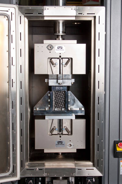
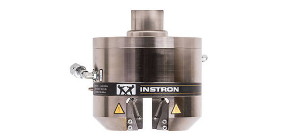
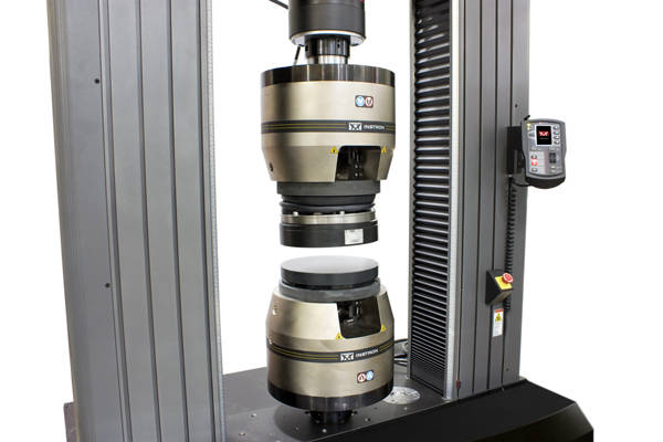
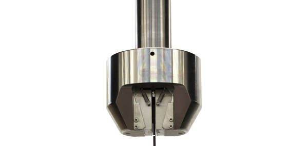
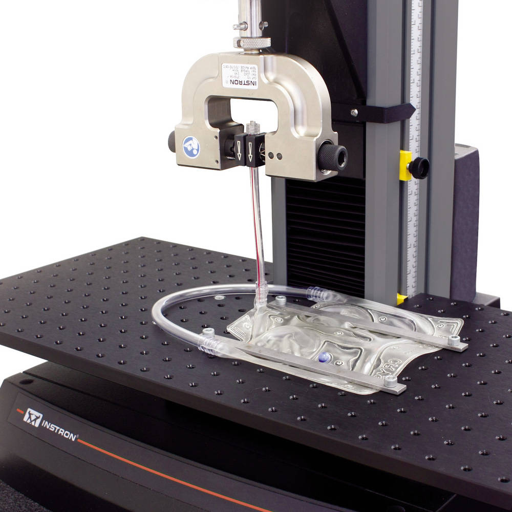
Dynamic Fatigue

Dynamic Fatigue LOAD CELLS

Dynamic Fatigue

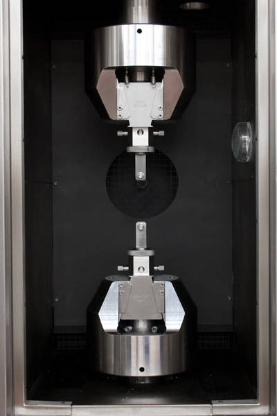
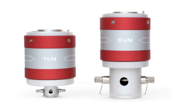
Dynacell is the world's first truly dynamic load cell, designed from the outset for measuring dynamic loads. Dynacell utilizes an accelerometer right at the heart of the load cell, directly on the load axis. This removes the risk of errors in the acceleration reading resulting from off-center loading.
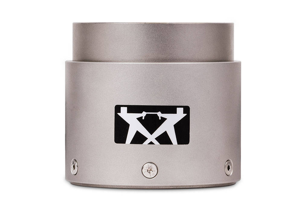
2527 Series Bi-axial Dynacell Load Cells

The 2527 Series load cells are designed for use with Dynamic Testing Systems; offering exceptional performance with the ability to measure forces as low as 1/250th of the force capacity to an accuracy of 0.5% of reading.
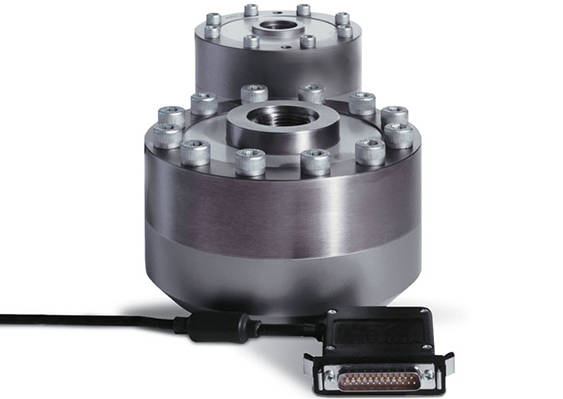
2527 Series Dynacell Load Cells

Dynacell is a unique load measurement device that automatically compensates for load errors induced through inertia of the load string components. A method of dynamic inertia compensation is essential for all forms of dynamic testing.

T-Slot Tables

T-SLOT TABLES

For Testing Components and Structures 

Tスロットテーブル

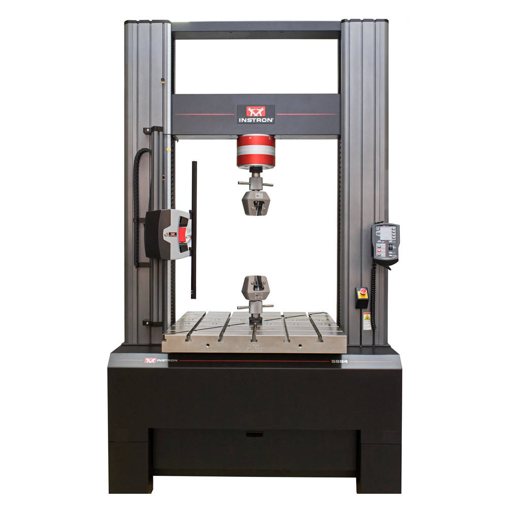
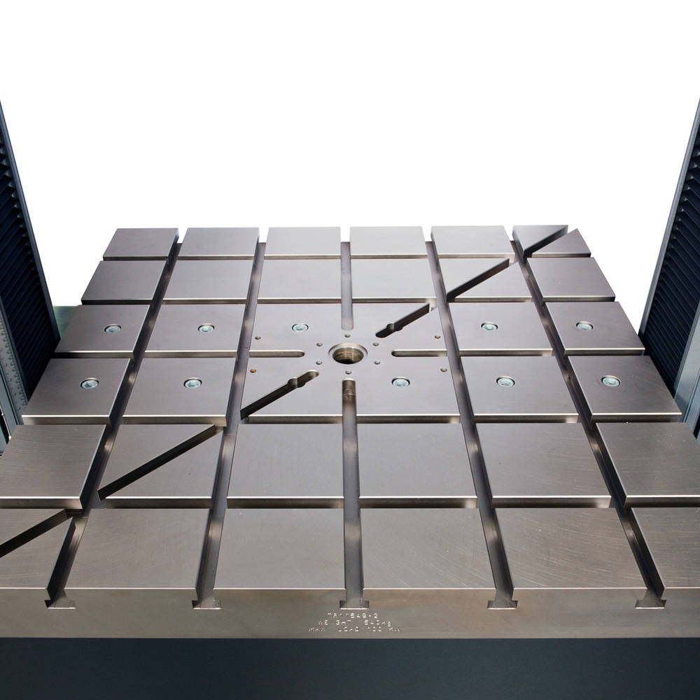
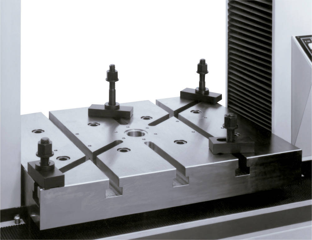
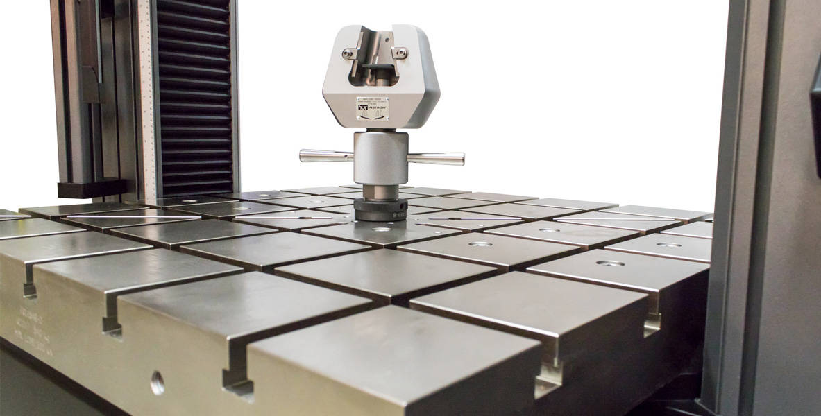
The T-slot table provides an extended work area for your universal testing system that offers a convenient way to secure components and structures for performing tensile, compression and flexural tests. The T-slot table gets mounted directly to the base of the machine and is equipped with T-slots that run front-to-back, side-to-side, and diagonally. Components and structures can then be secured in position on the table using the various clamping tools supplied. The design allows you to use standard Instron grips, text fixtures, and other major accessories without needing to remove the T-slot table from the frame.

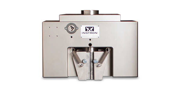
機械式くさびグリップとTスロットテーブル

Principle of Operation

T-slot tables allow users to secure components that can't be held with standard grips to a universal testing machine. Commercially available T-slot nuts are slid into the inverted T-slot of the table. Bolts, studs, or threaded rods can then be threaded into the nuts. The T-slot table can be used to secure specimens that might otherwise be ejected from the test space under load.

The T-slot table can also be used to position specimens in the same location for repeated tests or batch testing of product. Guides, slides, or stops can be positioned on the table and bolted into position to allow precise placement of the specimens for every test.

Application Range

  • Test types: tensile, compression, flexure, peel, cyclic (static)
  • Specimen type: components, structures
  • Common applications: automotive, electronics, biomedical, consumer products

Specifications
Catalog no. Maximum Capacity Compatible Frames Width Depth
CP103964 5 kN 3340, 4440, 5540, 5840, 5940, 34SC, 68SC Single Column Systems 200 mm 160 mm
2850-206 50 kN 3360 Table Model Systems 400 mm 500 mm
2850-205 50 kN 4460, 5560, 5860, 5960, 34TM, 68TM Table Model Systems 400 mm 500 mm
2850-203 300 kN 3382, 3384, 3385H, 34FM-100, 34FM-300, 4481, 4482, 4484, 4485, 5581, 5582, 5584, 5585, 5585H, 5881, 5882, 5884, 5885, 5885H, 5982, 5984, 5985, 68FM-100, 68FM-300 550 mm 500 mm
2850-202 600 kN 4400, 5500, 5800, 5900 Floor Model Systems Over 250 kN Capacity 640 mm 640 mm

Composite Tensile Grip Guide

Composite Tensile Grip Guide

This composite tensile grip guide provides an overview of key specifications for tensile grips that are ideally suited for testing composite materials. For a detailed look at the requirements and important issues related to gripping composite laminate coupons, read our Composites Gripping Guide White Paper.

Manual Wedge Action Grips
Grip Type Moving body wedge
Static Capacity 100 kN, 150 kN
Operation Manual
Interchangeable Yes
Temperature Range -70° to 315° C
Can You Attach Fixtures
Without Removing Grips? 
Some grips can be outfitted with adaptors to attach other fixtures - offering the flexibility to perform other tests without needing to remove the grips. This is referred to as piggybacking.
No
Nadcap Alignment No
Catalog Numbers 2716-002, 2716-003, 2716-008, 2736-004, 2736-005
Precision Manual Wedge Grips
Grip Type Moving body wedge
Static Capacity 100 kN, 250 kN
Operation Manual
Interchangeable Possible (not easy)
Temperature Range -80° to 250° C
Can You Attach Fixtures
Without Removing Grips? Precision Manual Wedge Grips with Composite Testing Fixture Attached
 
Some grips can be outfitted with adaptors to attach other fixtures - offering the flexibility to perform other tests without needing to remove the grips. This is referred to as piggybacking.
Yes
Nadcap Alignment Yes
Catalog Numbers 2716-028, 2716-030

Hydraulic Wedge Action Grips
Grip Type Moving body wedge
Static Capacity 130 kN, 312 kN, 600 kN
Operation Hydraulic
Interchangeable No
Temperature Range Ambient only
Can You Attach Fixtures
Without Removing Grips? Hydraulic Wedge Action Grips with Compression Fixture Attached
 
Some grips can be outfitted with adaptors to attach other fixtures - offering the flexibility to perform other tests without needing to remove the grips. This is referred to as piggybacking.
Yes
Nadcap Alignment Yes
Catalog Numbers 2743-401, 2742-501, 2742-601
Extended Hydraulic Wedge Action Grips

Extended Hydraulic Wedge Grips
Grip Type Extended moving body wedge
Static Capacity 130 kN, 312 kN
Operation Hydraulic
Interchangeable No
Temperature Range -70° to 350° C
Can You Attach Fixtures
Without Removing Grips? Extended Hydraulic Wedge Grips with Test Fixture Attached
 
Some grips can be outfitted with adaptors to attach other fixtures - offering the flexibility to perform other tests without needing to remove the grips. This is referred to as piggybacking.
Yes
Nadcap Alignment Yes
Catalog Numbers CP104947, CP109120

Impact Testing System Accessories

Impact Testing System Accessories

W-3572-B_J-Bolts_and-W-3572-D_Foundation-Template

Foundation Hardware for the MPX Series

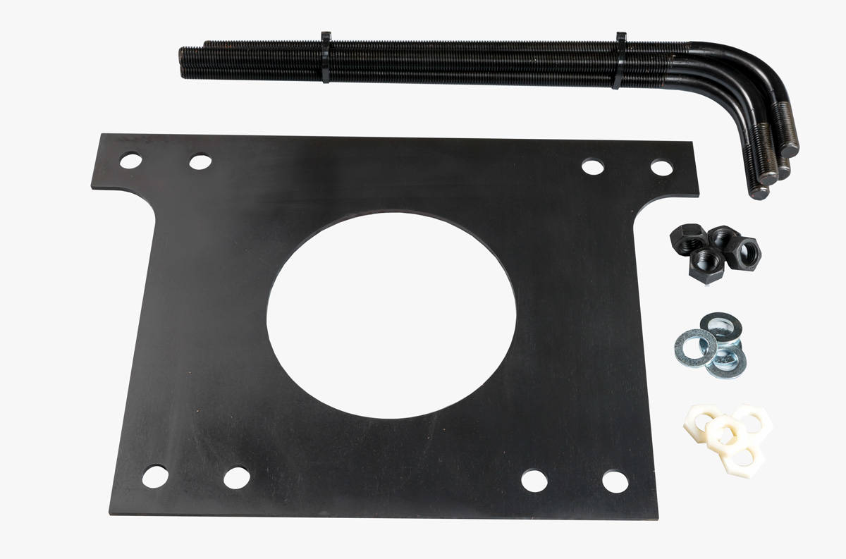
A template and hardware to attach the MPX to a concrete foundation.

Description Catalog No.
J Bolts | Includes 4 J-Bolts, Hex Nuts, Washers and Polymer Nuts W-3572-B
Foundation Template W-3572-D

Hammer Weight
Hammer Weight Hammer Weight

Hammer Weights for the MPX Series

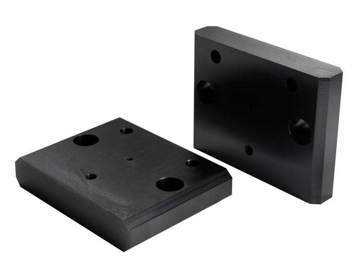
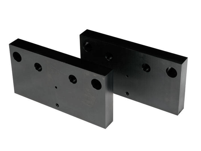
Hammer weights and attachment hardware for use with MPX Series frames of equal or greater capacity.

Description Catalog No.
300J Hammer Weight W-3576-A
450J Hammer Weight W-3576-B
600J Hammer Weight W-3576-C
750J Hammer Weight W-3576-D

W-3577_Hammer-Weight-Change-Kit-with-Hoist-400x400

Hammer Weight Change Kit with Hoist for MPX Series

Catalog No. W-3577

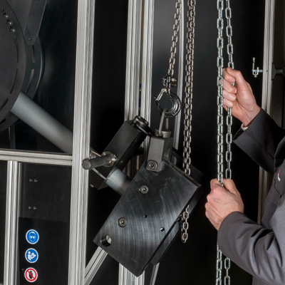
Kit includes a chain hoist with a capacity of up to 500 kgf (1100 lbf) and a frame mounting bracket to suspend the hoist from an MPX Series pendulum impact machine. This kit is used to easily lift and securely support the hammer weights during weight changes, or the pendulum hammer assembly when replacing the striker, anvils, or other wear components.

W-3598-Manual-Charpy-Specimen-Loader-Device

Manual Charpy Specimen Loader for MPX Series

Catalog No. W-3598

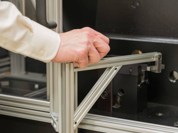
The Charpy specimen loader device attaches to the MPX frame and uses a manually operated pivoting arm to place individual specimens on the anvil for ambient testing. The arm must be moved away for the door to close and the test to be performed. Kit includes the specimen loader assembly and mounting hardware.
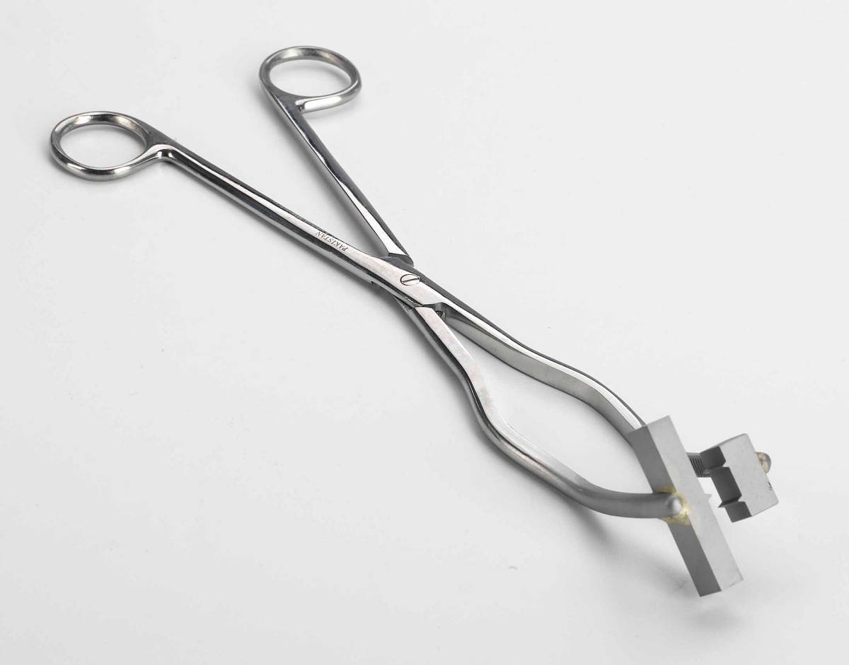
Charpy Tongs W-3550

Tongs

Tongs for handling and centering ambient and low-temperature Charpy and Izod specimens.

Description Catalog No.
Charpy Tongs W-3550
Izod Tongs W-3587-D

Charpy Test Kit

Charpy Test Kits

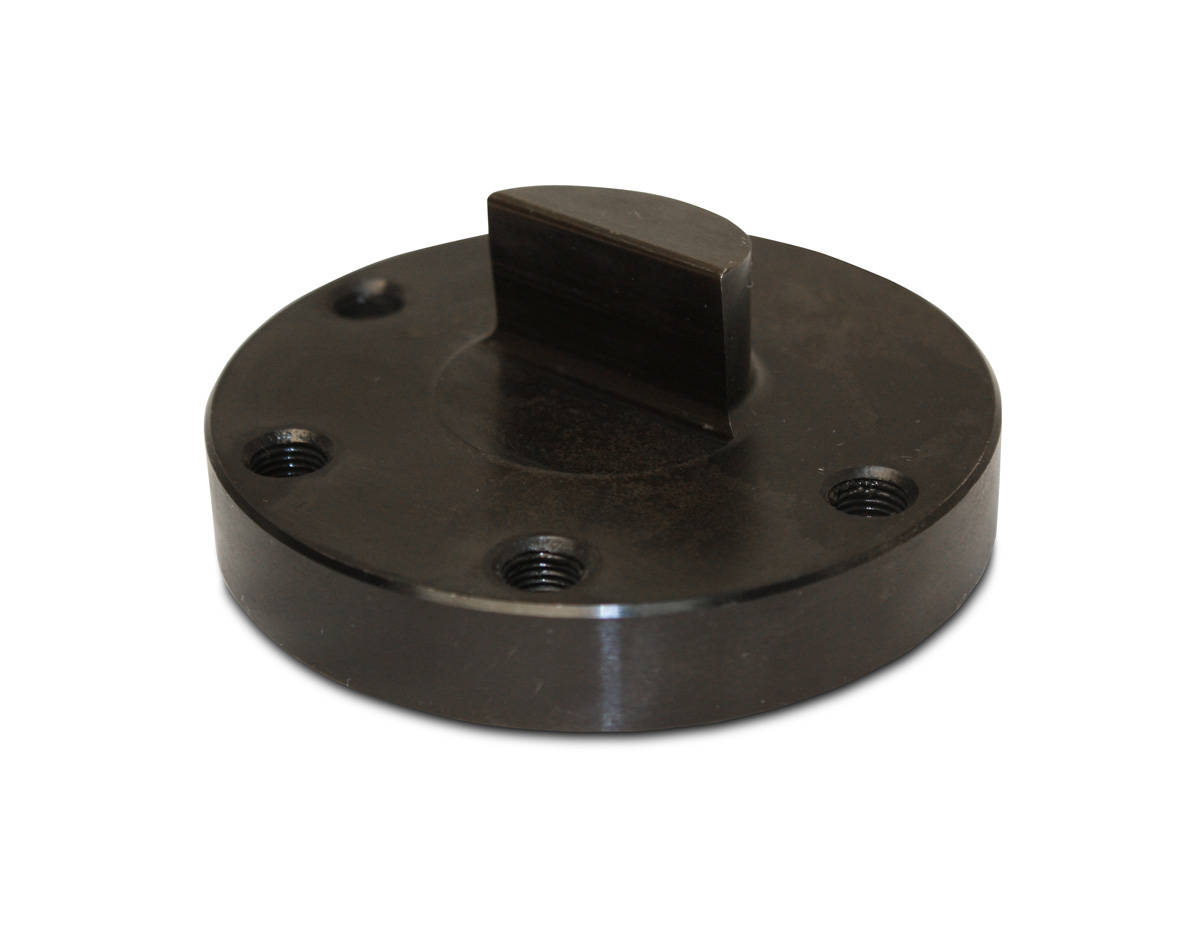
Charpy test kits include a Charpy impact striker, Charpy anvil inserts, and shrouds. These are for use on SI and MPX Series pendulum impact testing systems.

Description Catalog No.
Charpy Test Kit for ISO 148-2:2009
Includes: Charpy impact striker (2 mm Radius), and Charpy anvil inserts (1 mm radius), and shrouds
W-3599-A
Charpy Test Kit for ASTM E23-12C (also complies with ISO 148-2:2009)
Includes Charpy impact striker (8 mm radius), and Charpy anvil inserts (1 mm radius), and shrouds
W-3599-B

Izod Test Conversion Kit

Izod Test Conversion Kit

Catalog No. W-3587-C

Izod test conversion kit includes the components required to convert an MPX and SI Series pendulum impact tester to conduct an Izod test. Included are tongs for specimen handling, a magnetic specimen retrieval device and other necessary tooling. An Izod striker is not included.

W-3599-D-Charpy-Impact-Stiker

Charpy Impact Strikers

Additional or spare Charpy impact strikers can be provided for testing with either a 2 or 8 mm radius.

Description Catalog No.
Charpy Impact Striker (2 mm radius) for ISO 148-2:2009 W-3599-C
Charpy Impact Striker (8 mm radius) for ASTM E23-12C (also complies with ISO 148-2:2009) W-3599-D

Izod Impact Striker

Catalog No. W-3587-A

Izod impact striker for machine capacities 240 ft-lbf (325.4 joule) and greater.

Charpy Specimen Support Sets

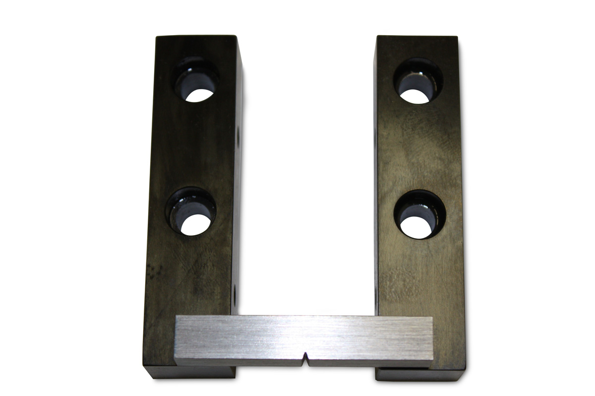
Charpy specimen support sets are for use with SI and MPX Series pendulum impact testing systems and are compliant with ASTM E23-12C and ISO 148-1:2009.

Description Catalog No.
Standard (10 mm x 10 mm) Charpy Specimen Support Set W-3585
Subsize (7.5 mm x 10 mm Charpy Specimen Support Set (Set of 2) W-3596
Subsize (5.0 mm x 10 mm Charpy Specimen Support Set (Set of 2) W-3595
Subsize (2.5 mm x 10 mm Charpy Specimen Support Set W-3594

W-3609-Charpy-Cooling-Bath

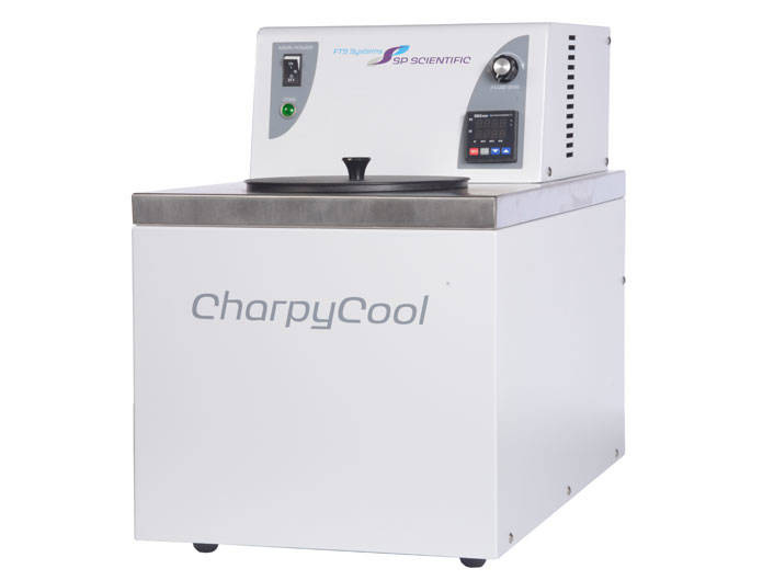
FTS Charpy Specimen Cooling Baths

FTS Charpy Specimen Cooling Bath includes Charpy rack that holds up to 65 specimens and exceeds ASTM E23 / ISO 148 temperature stability requirements.

  • Temperature Control Range: -80 C to +30 C, +/- 0.1 C
  • Bath Volume: 4 liters
  • Approved: UL#61010-1, CAN / CSA 22.2 #61010-1, CE (2006/42/EC), (2006/95/EC), (006/108/EC).

Note: Performance specifications are based on SP Scientific test data from units using methanol and operating at an ambient room temperature of approximately 22 C (72 F). Higher ambient temperatures and/or different fluids may interfere in the system's ability to achieve its ultimate low temperature.

Description Catalog No.
220 V Cooling Bath (50 Hz, 6 AMP) W-3609-A
120 V Cooling Bath (60 Hz, 12 AMP) W-3609-B

W-3558-Charpy-Centering-Gauge

Charpy Centering Gauge

Catalog No. W-3558

A centering gauge for positioning Charpy anvil and pendulum.

W-3561-Lateral-Expansion-Gauge

Charpy Lateral Expansion Gauge

Catalog No. W-3561

A lateral expansion gauge for impact testing in accordance with ASTM A370.

Environmental Chambers

ENVIRONMENTAL CHAMBERS

For Testing at Non-Ambient Temperatures

Environmental Testing Chambers

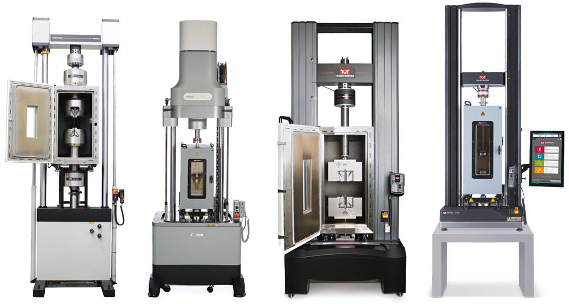
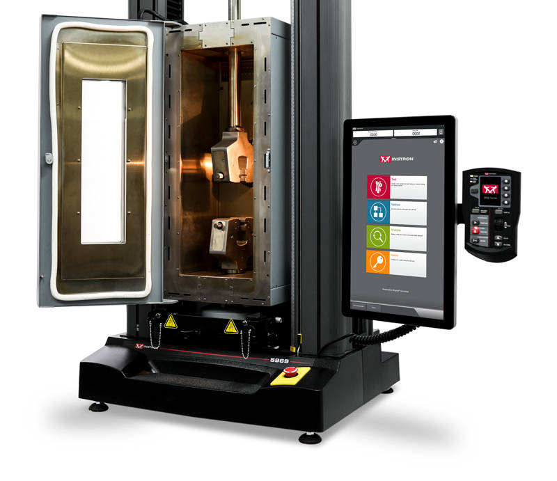
Compatible with both static and dynamic testing machines, the 3119-600 Series environmental chambers provide extensive temperature testing capabilities for evaluating material properties under non-ambient conditions. Chambers are available in a wide range of standard dimensions and can be fixed to the machine or mounted on roller brackets. They can also be fitted to other makes of testing machines with custom mountings, if needed. In addition, Instron can tailor complete solutions, including load string components, if the requirements for your application fall outside of the specifications of our standard chambers, grips, and fixtures.

Principle of Operation

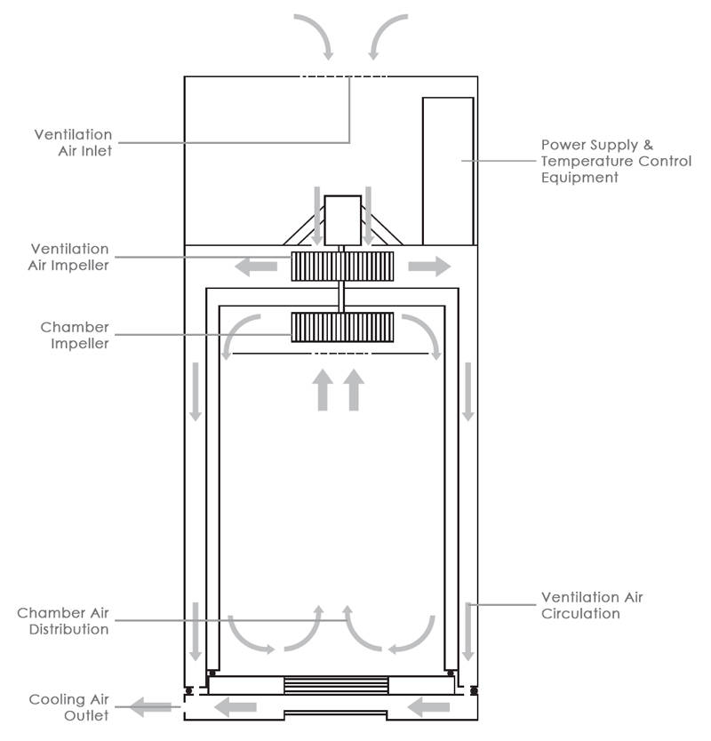
Instron environmental chambers use a forced-convection principle in which hot or cold air is circulated around the specimen, grips, and pull rods to provide optimum heating/cooling rates, reduced thermal gradients, and good thermal stability. Ambient temperature air is also passed from the rear of the chamber into the space between the insulation and the outer panels. This helps to keep the outer skin of the chamber cool. The selectable high/low fan speed allows delicate specimens to be tested by reducing the effect of air turbulence within the chamber.

Features and Benefits

  • Advanced functions include 8-segment ramp/dwell, USB interface, and analog DC output capability
  • Removable wedge ports provide quick and easy loadstring setup and incorporate instrumentation cut-outs for extensometer cables without interfering with the pull rods
  • Dedicated cryogen exhaust port makes safe venting simple
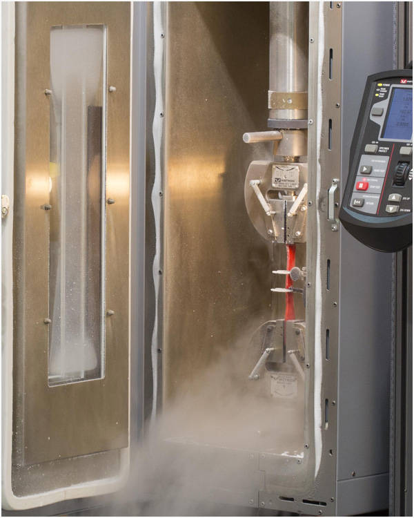
  • Triple-pane, optical quality borosilicate glass window with twin cartridge heaters for minimizing frosting and misting when testing at low temperatures
  • Full 3-term PID temperature controller with auto-tune combines simplicity and flexibility to cover a range of testing requirements
  • Selectable slow fan speed improves testing of delicate specimens at low forces by reducing air turbulence
  • Interlock switch on floor model chambers for water-cooled grips shuts chamber down automatically if water flow is interrupted
Environmental Chamber Drawing

HEATING AND COOLING

Heating is achieved by passing air over an electrically heated element. All chambers in the range come with heating as standard. Cooling is achieved by blowing cryogenic gas (either CO2 or LN2) into the chamber via an optional cooling valve. The cryogenic gas is normally stored in cylinders (liquid CO2) or a self-pressurizing Dewar (liquid N2). Waste cryogenic gas is exhausted to the rear of the chamber through a dedicated port to which a silicone rubber pipe can be attached and vented outside the laboratory environment.

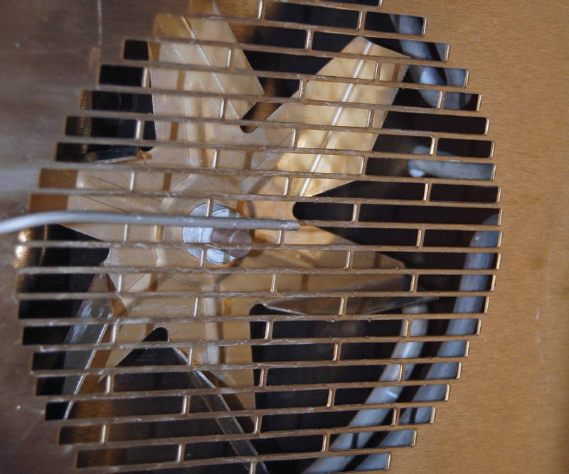
Fan
Instron 5960 Series Table Top Model

SPECIMEN ACCESS

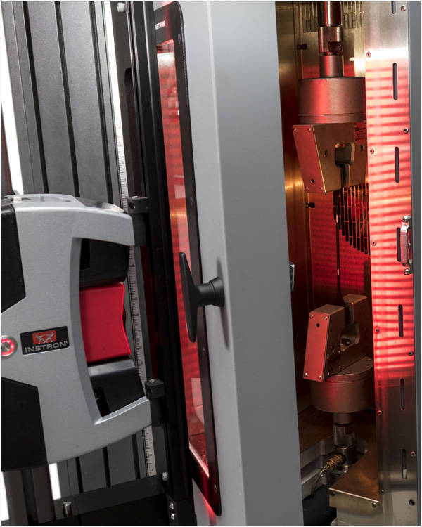
Access to the specimen and grips is via a left-hand hinged door that also contains a heated, optical-glass window. An internal light allows the inside of the chamber to be clearly seen if required. The chamber automatically turns off heating, cooling, and the fan when the door is opened, reducing the hot/cold air reaching the operator.

TEMPERATURE CONTROL

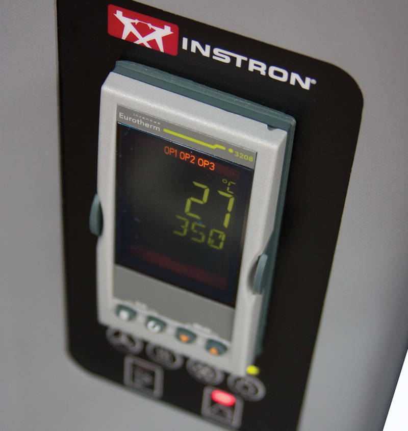
A dedicated Eurotherm 3208 temperature controller mounted to the chamber is used to select the required set-point temperature. Temperature is monitored and controlled by a Type N thermocouple inside the chamber. The controller can be programmed with defined heating rates and dwell times (8 segments), as well as communicate with a PC via USB using compatible Instron software. It also features a 0-10V analog output of temperature for use by other devices, such as chart recorders.

Temperature Controller

Accessories

The 3119-600 Series environmental chambers are compatible with a comprehensive line of grips, fixtures, extensometers, and push/pull rods to offer a reliable and enduring performance for a wide range of testing applications where non-ambient testing conditions are required.

STANDARD CHAMBERS

6800 Series Universal Testing System with an Environmental Chamber


Chambers for Table Model Systems
Catalog
Number
Temperature
Rating  Cooling option required to achieve temperatures below ambient levels.
Internal
Dimensions  Depth x Width x Height
External
Dimensions  Width x Height
3119-605 -100 °C to 350 °C 230 x 240 x 485 mm 350 x 635 mm
3119-606 -100 °C to 350 °C 230 x 240 x 560 mm 350 x 710 mm
3119-609 -100 °C to 350 °C 230 x 240 x 660 mm 350 x 810 mm
3119-615 -100 °C to 350 °C 230 x 240 x 860 mm 350 x 1010 mm
6800 Series floor model with BlueHill Universal and an environmental chamber

Chambers for Floor Model Systems
Catalog
Number
Temperature
Rating  Cooling option required to achieve temperatures below ambient levels.
Internal
Dimensions  Depth x Width x Height
External
Dimensions  Width x Height
3119-607 -150 °C to 350 °C 400 x 400 x 560 mm 550 x 710 mm
3119-608 -150 °C to 600 °C 400 x 400 x 560 mm 550 x 710 mm
3119-610 -150 °C to 350 °C 400 x 400 x 660 mm 550 x 810 mm
3119-616 -80 °C to 350 °C 400 x 400 x 900 mm 550 x 1050 mm
3119-617 -80 °C to 350 °C 400 x 400 x 760 mm 550 x 910 mm
3119-618 -80 °C to 350 °C 400 x 400 x 1000 mm 550 x 1050 mm

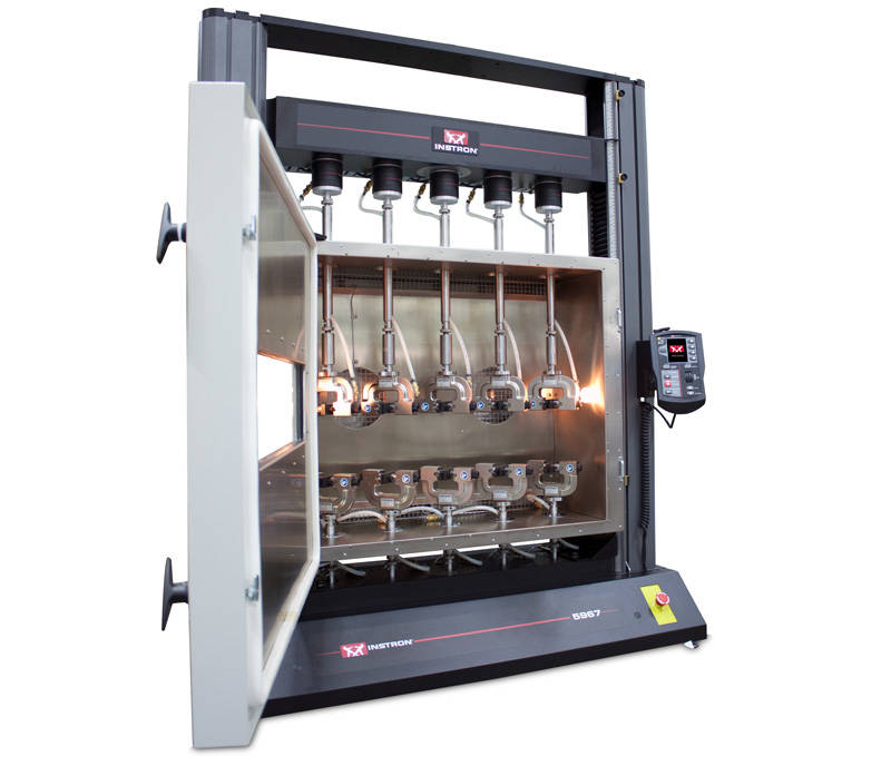
5900 Series Multi-Station Test Frame with Environmental Chamber

CUSTOM CHAMBERS

For those testing applications that require more than a standard chamber offers, our Engineered Solutions Group is available to design specialized environmental chambers to fit your needs, including taller or wider chambers, chambers with higher temperature ratings, and custom load string components, such as grips and fixtures.

Cord Capstan Tensile Grips

CORD CAPSTAN TENSILE GRIPS

Catalog no. 2715-001

Cord Capstan Grips

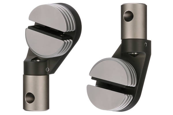
Cord capstan grips are designed to permit faster, easier testing of twisted or braided cords. These grips are designed to permit predetermination of specimen length, and allow quick, convenient loading.

Request A Quote

Principle of Operation

Cord capstan grips provide a superior method for clamping twisted or braided cord during testing. Each grip has a round capstan with a right-hand spiral grooved surface that accommodates specimens up to 3.2 mm (0.125 in) in diameter. The capstan is split axially into two halves, one half being stationary and the other movable. The specimen is wound from the outside of the capstan towards the center before being passed through the split halves where it is clamped. The groove completes 2.5 turns around the capstan, which allows two full turns for distributing the specimen load and stress concentration. The grips self tighten as load is applied to the specimen.
Smooth capstan surfaces are available separately.

Application Range

  • Type of loading: tensile, static only
  • Specimen materials: twisted or braided cord
  • Specimen shapes: cord or strips

2715-001-01-19
Specifications
Catalog no. 2715-001
Force Capacity 2.5 kN
Maximum Specimen Diameter 3.2 mm
Temperature Range -73 °C to 316 °C
View Full Specifications Download Brochure

O-Ring Test Fixtures

O-Ring Test Fixtures

O-Ring Test Fixture
O-Ring Test Fixture
O-Ring Test Fixtures


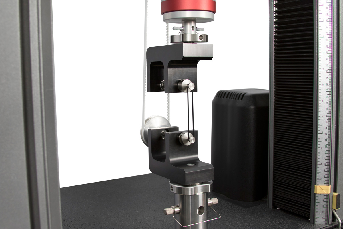
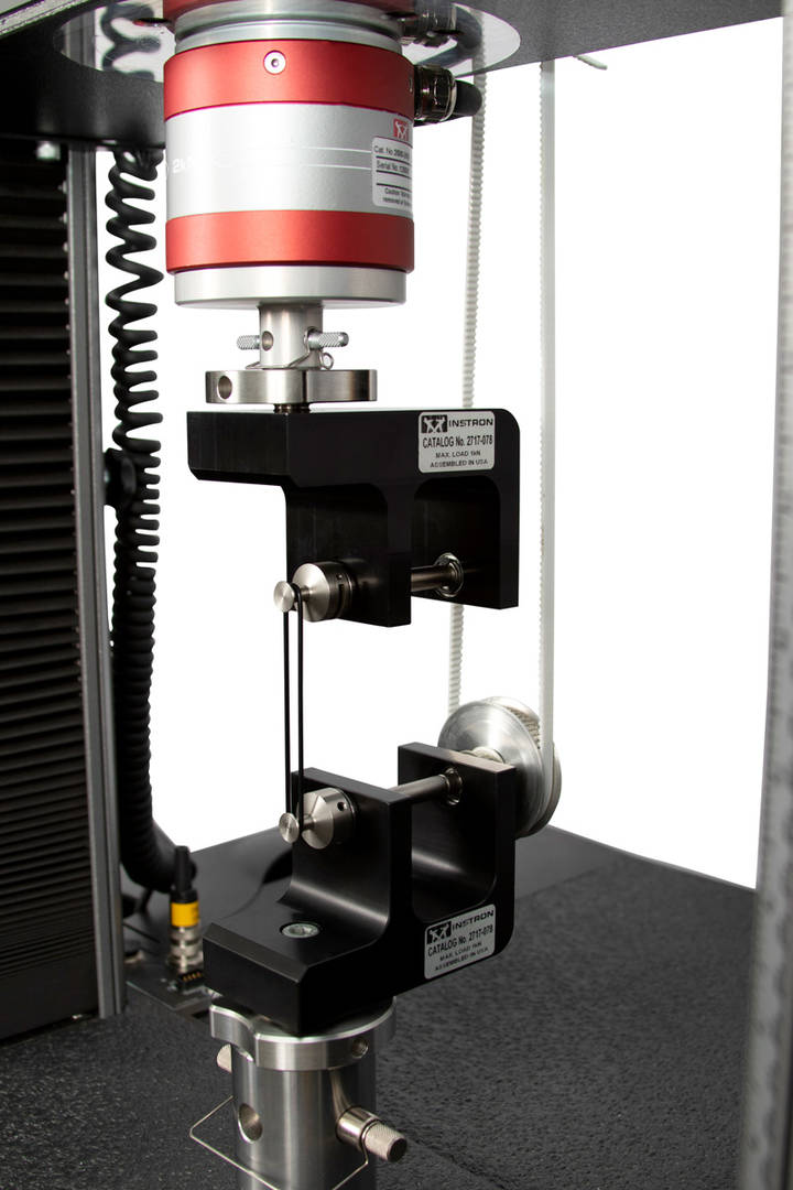
The O-ring test fixture is designed to facilitate the testing of O-rings and other similar continuous loop specimens where it is essential to minimize localized stressing in the sample. With a maximum capacity of 1 kN, these fixtures feature interchangeable spindle sets of various diameters and thicknesses that can be easily swapped out to meet a range of testing standards.

Compatible Frames Catalog Number
Single Column Systems:
334X, 34SC, 444X, 554X, 584X, 594X, 68SC systems with 1 kN or greater capacity
2717-068
Table Model Systems | Standard Height and Extra Height:
336X, 34TM, 446X, 556X, 586X, 596X, 68TM
2717-078
Interchangeable Spindles


Roller Diameter Roller Width Relevant Standard Catalog Number
3.18 mm 7 mm 2717-074
4.75 mm 7 mm D412 Proc. B 2717-070
6.35 mm 7 mm 2717-075
12.7 mm 7 mm ASTM D1414 2717-076
15 mm 25 mm BS 3704 2717-071
18.3 mm 7 mm DIN 53504 R2 2717-073
22.3 mm 7 mm DIN 53504 R1 2717-072

More Info

Compression Platens

COMPRESSION PLATENS

For Universal, Dynamic, and Fatigue Testing Machines

2501 Series Compression Platens

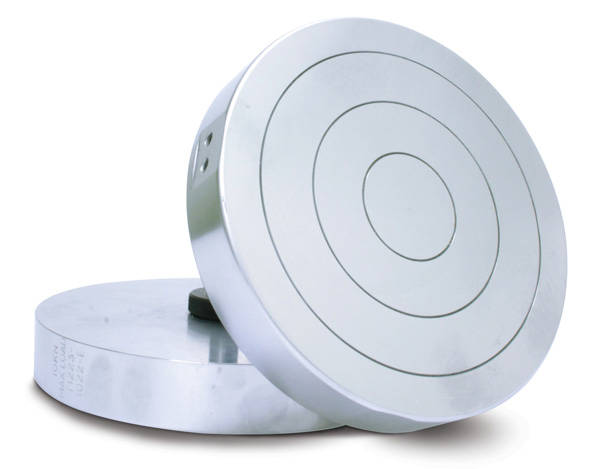
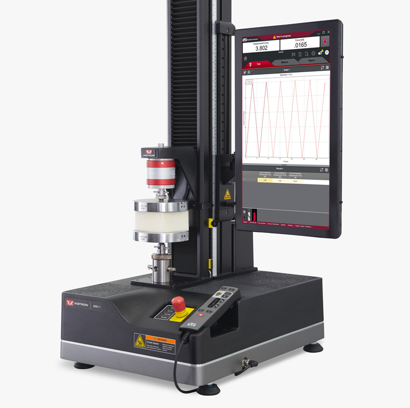
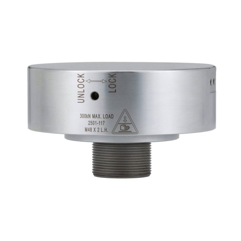
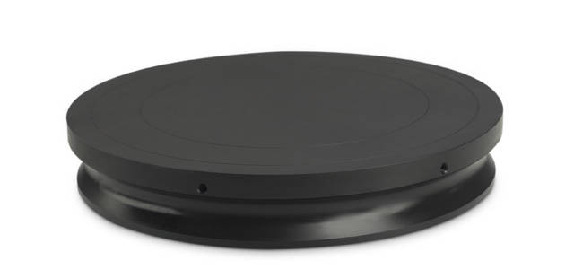
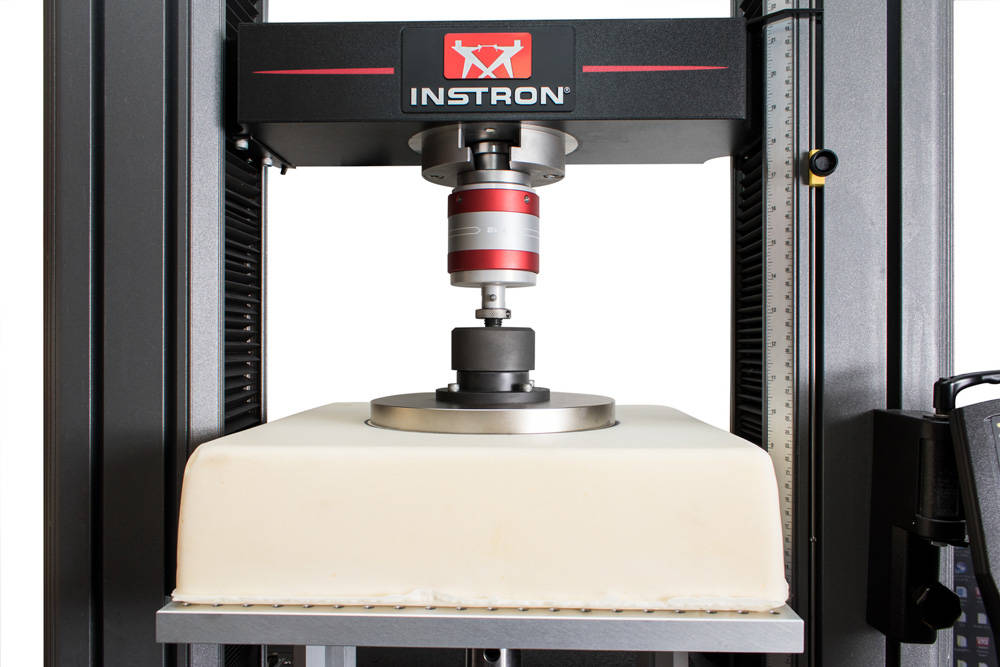
Compression platens are used to perform compression tests on a wide range of materials and components. When installed in a universal testing machine, compression platens allow a variety of tests to be performed to determine compression modulus, compression strength, and compression yield strength.

Foam Compression Test on 68SC

2501 Series Compression Platens

50 N - 600 kN Load Capacities

Principle of Operation

Easy to install, the 2501 Series compression platens are precisely machined fixtures designed for even distribution of compression loads during a test. These platens have a hardened surface (Rockwell HRC 58/60) for compression tests in which uniform stress distribution is critical.

Application Range
  • Type of loading: Static compression, compression-compression cyclic tests
  • Specimen material: Foam, plastics, metals and alloys, packaging, wood, composites, ceramics, and other materials
  • Specimen shapes: Square, cylindrical cubes, components
2501 Series Compression Platen Key Features
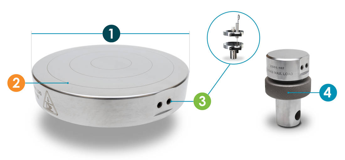
Key Features
  1. Sizes and Load Capacities — While the 50 mm and 150 mm diameter platens are most common, the 2501 Series is offered in a range of sizes between 25 mm – 300 mm with load capacities between 50 N – 600 kN.
  2. Concentric Rings — To aid the operator on the larger diameter anvils, the 150 mm to 300 mm diameter platens are laser etched with concentric rings to allow for easier centering of the specimen body.
  3. LVDT Mounting — The platen edge has a provision for the attachment of optional displacement transducers, allowing you to measure the direct displacement between two equal sized platens during a test.
  4. Lock Nut Design — Designed for easy hand-tightening to eliminate backlash.
360° View

2501-163-V1-02-08

2501-117-V1-01-23

68SC-12501-083-V1-01-01

68TM-502501-162-V1-01-17

Additional Compression Platen Models

Self-Aligning | High Force | Fatigue Rated

Self-Aligning / Spherical Seatings
For Static and Dynamic Testing Applications

During the application of a small preload, the spherical seated compression platen provides the self-alignment required to accommodate compression specimens which have surfaces that are not completely parallel.

Industrial Series Compression Platens
600 kN - 5000 kN Load Capacities | Catalog Numbers W-2004 and W2005

Instron's Industrial Series Compression Platens are engineered to deliver optimal performance in compression testing at high forces. These durable, high‑strength platens come in both plane and self‑aligning versions and can be easily integrated with Instron systems as well as other static universal testing machines.

Foam Compression Fixture
Foam Compression Fixture Foam Compression Fixture
Foam Compression Fixture
Catalog Numbers 2810-130

This foam compression fixture is designed for indentation and compression testing of expanded cellular materials and meets standards such as ASTM D3574 (Methods B1/B2), ASTM D5672, ISO 2439 and ISO 3386.

The perforated loading table features 6.5 mm holes spaced on 20 mm centers and is elevated from the mounting surface, allowing for rapid air escape. The upper attachment is a 203 mm diameter indentor / anvil that incorporates a swivel joint.

2840 Series Compression Platens
2840 Series Compression Platens for Dynamic Testing
200 kN - 2000 kN Static Load Capacities | 100 kN - 1000 kN Dynamic Load Capacities

The 2840 Series compression platens incorporate LVDT mounting and are designed for reliable compressive high-cycle fatigue testing.
Electronics and Microelectronics Testing Systems and Accessories

Whether your application involves displays, buttons, wires, batteries, full devices, or microelectronic components and assemblies such as printed circuit boards and chips, Instron offers a comprehensive range of testing accessories for tensile, compression, bend, peel, shear, and puncture testing. All accessories are engineered for the precision and repeatability that electronics and microelectronics testing demands — where forces are often measured in millinewtons and specimen dimensions in microns.
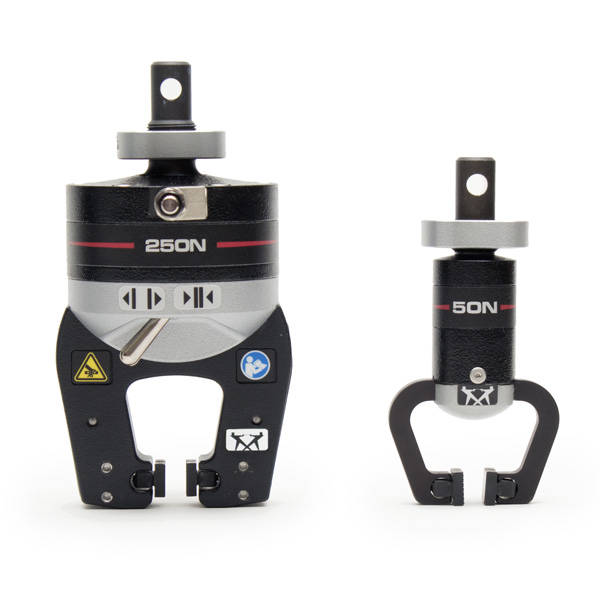
250 N and 50 N Pneumatic Side Action Tensile Grips

Instron offers a variety of grips for tensile testing of electronic devices and microelectronic components — including leads, wires, thin films, and irregularly shaped assemblies. Select grip models feature jaw faces that can be offset to accommodate lap shear testing of bonded components.

Available Grips

Description Capacity Catalog Number  
Pneumatic Side Action Tensile Grips 50 N - 10 kN 2712-04x and 2712-05x Series Learn More
Screw Side Action Tensile Grips 100 N - 10 kN 2710-100 Series Learn More
Micro Pneumatic Side Action Tensile Grips 10 N 2712-101 Learn More
Pneumatic Lead Pull Grip 500 N 2712-212 Learn More
Wire Pull Hook Fixture 10 N 2860-001 Contact Us

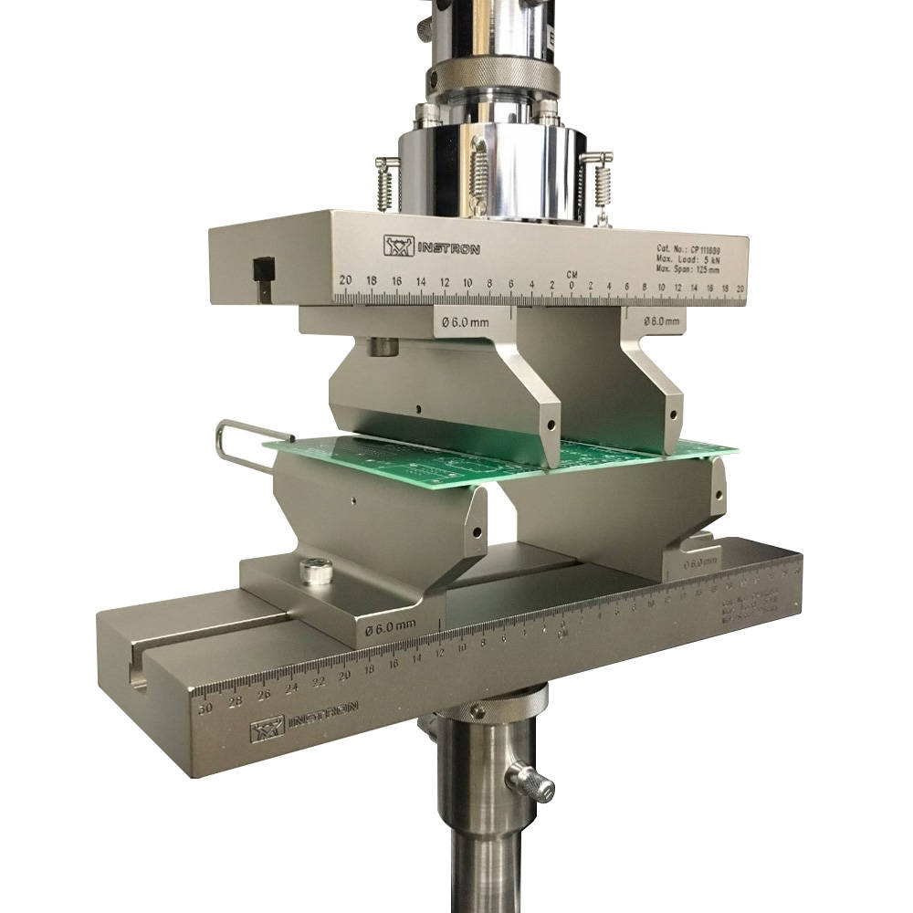
Bend Fixture Testing Microelectronic Component
Bend Fixture Testing Microelectronic Component 5 kN Flexure Fixture 4 Point Bend Fixture to JEDEC 9702

Flexure Fixtures

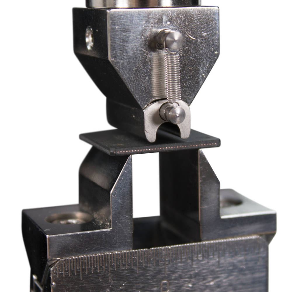
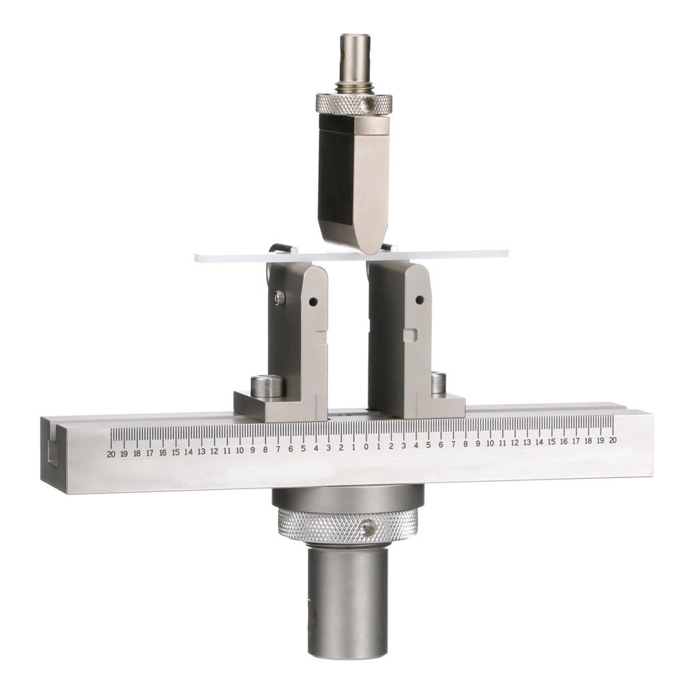
Three-point and four-point bend fixtures are used to characterize the flexural strength of electronic devices, components, and miniature microelectronic components. In addition to the fixtures listed below, Instron manufactures a variety of larger bend fixtures with wider spans for testing displays and full-size devices — contact us for details.

Available Fixtures

Description Capacity Span Catalog Number  
5 kN Flexure Fixture 5 kN 10 - 194 mm
4 - 188 mm
2810-400 More Info
4 Point Bend Fixture to JEDEC 9702 5 kN Max Upper: 125 mm
Max Lower: 225 mm
CP111689 Contact Us
3 & 4 Point Bend Fixture for Glass Testing 2 kN 20 - 200 mm CP120055 More Info
Miniature 3 Point Bend Fixture
Optional 4 Point Anvil
2 kN
2 kN
3 - 105 mm 2810-412
2810-413
More Info
Micro 3 Point Bend Fixture 1 kN
100 N
3 - 10 mm
1 mm
2810-411
2810-410
More Info
High Precision Micro 3 Point Bend Fixture to SEMI G86-0303 1 kN
1 kN
3 - 10 mm
3 - 25 mm
CP101568
CP117370
More Info
Instron Microelectric peel fixture

Adhesive Test Fixtures

Peel and stud pull fixtures are used for testing the adhesive bond strength of laminated materials and bonded components — including copper runners on printed circuit boards, thin film coatings, adhesive tapes, semiconductor dies, and other bonded structures.

Available Fixtures

Description Capacity Catalog Number  
90° Angle Peel Fixture 1 kN 2820-035 Learn More
Variable Angle Peel Fixture 1 kN 2820-036 Learn More
Miniature 90 Degree Peel Fixture 1 kN 2820-034 Learn More
Miniature Variable Angle Peel Fixture 1 kN 2820-033 Learn More
Stud Pull Fixture
Specimen Preparation Fixture for Stud Pull Tests
5 kN 2860-300
2860-301
Learn More
Stepped Jaw Vice Clamp 500 N 2860-210 Learn More

Three-Jaw Chuck
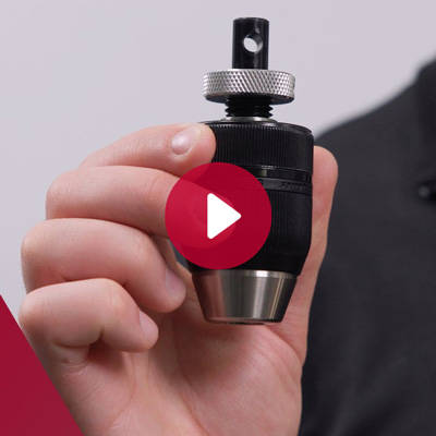
Three-Jaw Chuck Three Jaw Chuck Video Testing Probes

Three-Jaw Chuck and Testing Probes

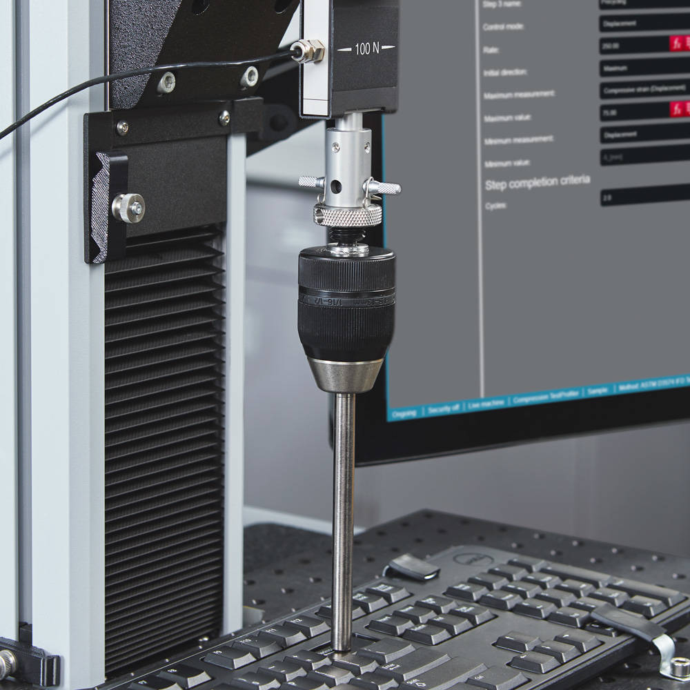
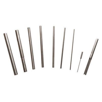
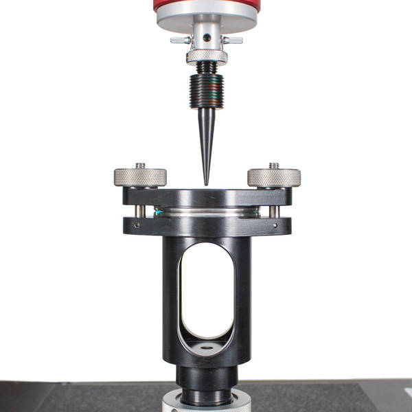
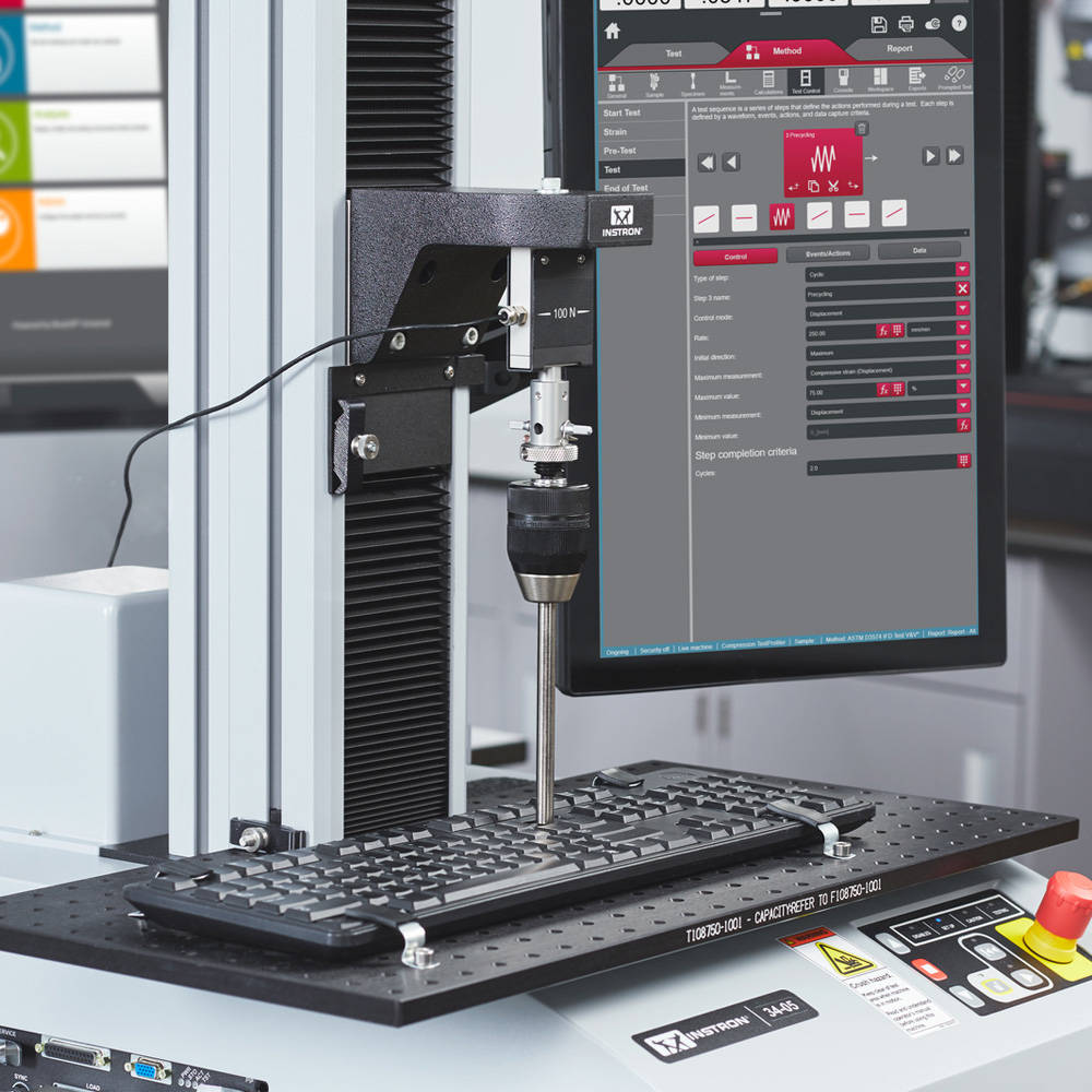
The three-jaw chuck is a versatile fixture for holding cylindrical or irregularly shaped specimens during compression testing. A variety of probes can be attached to the chuck for performing point-based compression tests on buttons, displays, and other electronic and microelectronic components — providing a quick and secure way to adapt the testing system to a wide range of specimen geometries without custom tooling.
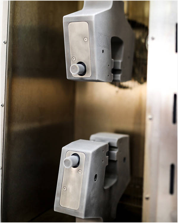
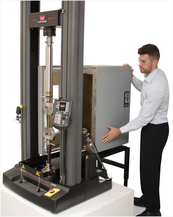
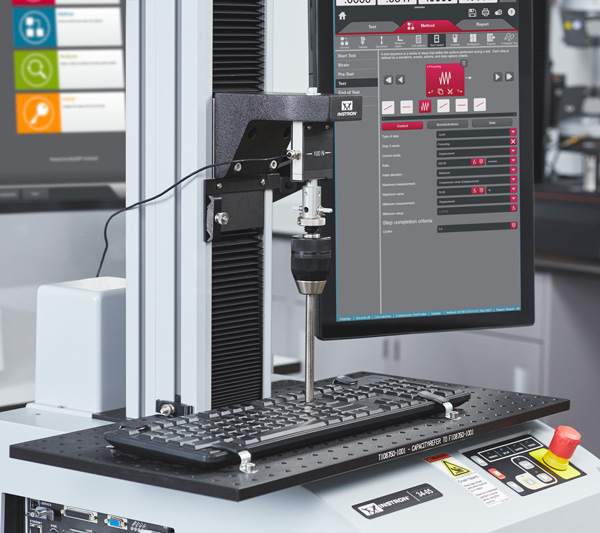
Component Test Plate | Keyboard Button Testing

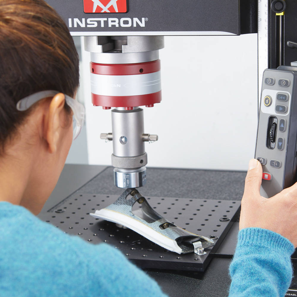
The component test plate is a large plate featuring an array of tapped holes that allows difficult-to-test components and assemblies to be secured in the correct position for tensile, compression, peel, or other mechanical tests. The tapped hole array provides multiple attachment points for custom fixtures and clamps, making it a versatile platform for testing components that cannot be held by standard grips or fixtures.

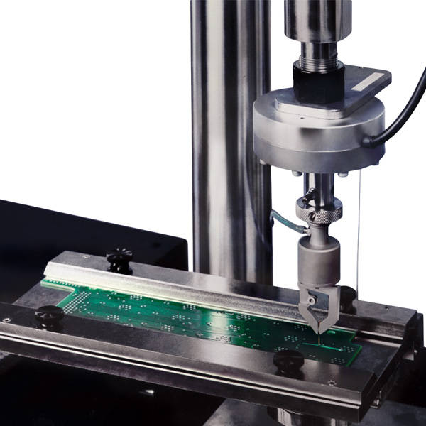
Automated XY stage on a 6800 Series 68TM table model, positioning a printed circuit board array over a flexure fixture for automated bend testing.
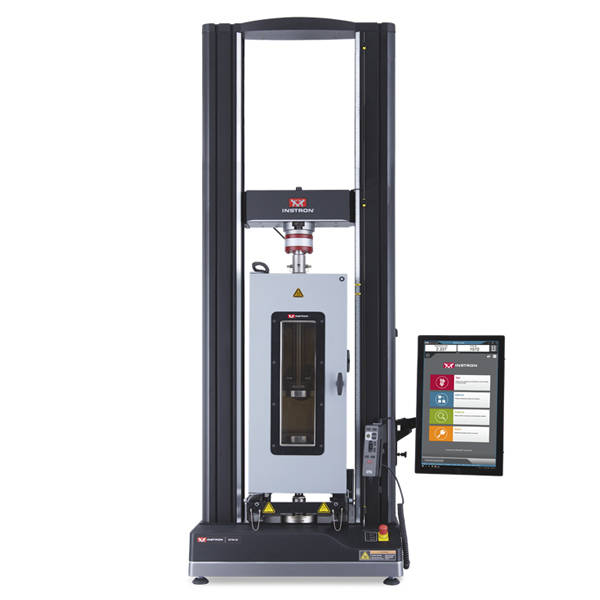
AT2 Automated XY Stage

Automated XY stages enable automated compression, flexure, and tensile testing of multiple specimens in a single test run, or testing of devices and components with multiple test points — significantly improving throughput and repeatability compared to manual single-point testing. Commonly used for displays, buttons, keyboards, and electronic components.
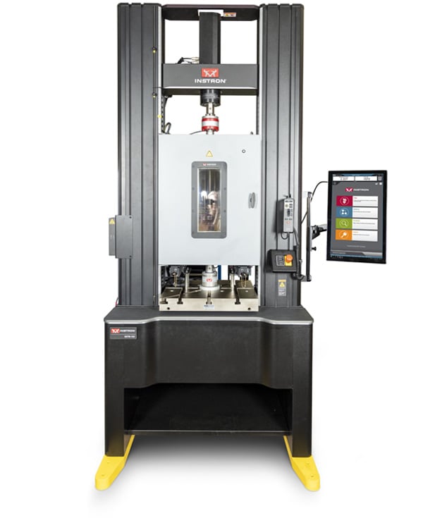
Frame Compatibility

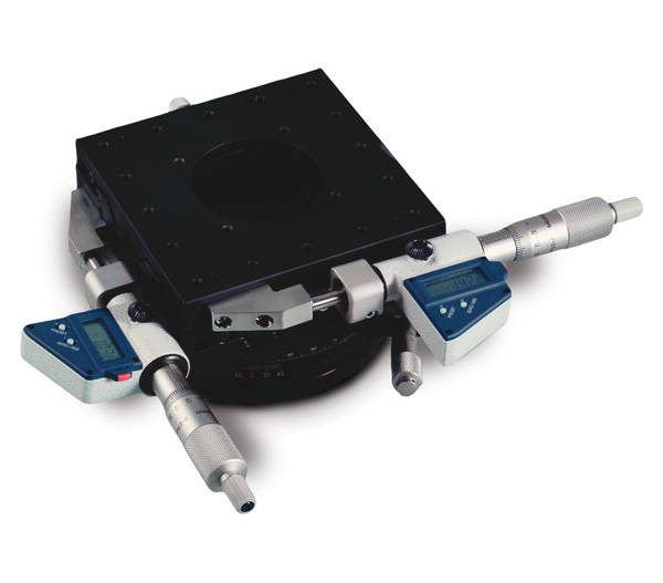
Manual Translation Stage

Translation and clamping stages provide precise positioning and alignment of test specimens below the actuator — essential for microelectronics testing where the probe must be centered accurately on the target component or test point. Commonly used for positioning printed circuit boards, chip packages, and other small components within the testing system.

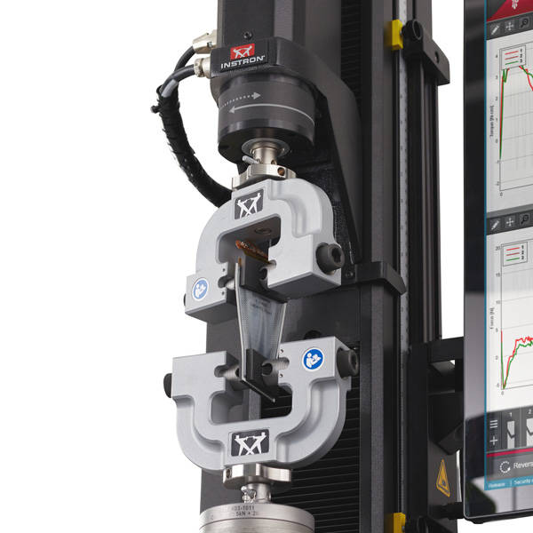
Torsion Add-On

The Torsion Add-On 3.0 enables simultaneous or independent axial and torsional testing on 6800 Series universal testing systems — expanding laboratory capability to include torsion testing of flexible electronics, components, buttons, wires, and flexible printed circuits. Ideal for simulating the real-world twisting and flexing loads that flexible electronic products experience in use and during assembly.

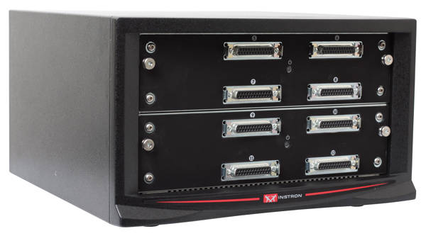
Expansion Channel Module

Digital I/O boards and expansion channels can be added to universal testing frames to interface with external measurement devices — including voltage and resistance measurement equipment used in microelectronics testing to correlate electrical output with applied mechanical load. This enables simultaneous capture of mechanical and electrical data within Bluehill® Universal software.

To ensure that your test results are of the highest quality, Instron designs and manufactures all of our own load cells. Instron load cells are carefully engineered to meet the unique requirements of materials testing systems, including high accuracy over a wide measurement range, high stiffness, resistance to offset loads, accurate alignment, and excellent zero stability. For electronics and microelectronics testing, we offer a wide range of low capacity load cells suitable for testing at low forces.

Commonly Used Capacities

Description Catalog Number  
5 N Static Load Cell 2530-5N Learn More
10 N Static Load Cell 2530-10N Learn More
50 N Static Load Cell 2530-50N Learn More
100 N Static Load Cell 2530-100N Learn More
500 N Static Load Cell 2580-500N Learn More
1 kN Static Load Cell 2580-1KN Learn More
2 kN Static Load Cell 2580-2KN Learn More
5 kN Static Load Cell 2580-5KN Learn More

Many electronic devices and microelectronic components are expected to withstand extreme temperatures both during the assembly process and in normal use. With an environmental chamber, you can characterize the performance of your products under a wide range of temperature conditions ranging from -100 °C to +350 °C.

Shear Testing Fixtures

Shear Testing Fixtures

Die and package shear test fixtures are designed to determine the integrity of the connection between a semiconductor die or surface mounted passive elements to package headers or other substrates. These fixtures are used to measure the shear force required to initiate failure of glue, solder, sintered silver, or other bonding agent in accordance with various testing standards, such as MIL STD 883, IPC TM-650, AEC-Q200-006A, or ASTM F1269-13.

Available Fixtures

Description Capacity Catalog Number  
Terminal Strength Shear Fixture 500 N CP122690 Learn More
Shear Test Fixture to MIL STD 883 2 kN CP124648, S4781A,
CP127130, S4752A
Learn More
Shear Testing Fixtures

Burst or puncture fixtures are commonly used to test packaging, fabrics, and thin films and separator films found in batteries to determine the resistance of a material to the penetration of a probe. The material is typically held by a set of clamping rings, and undergoes biaxial stresses representative of those encountered during actual use.

Available Fixtures

Description Capacity Catalog Number  
Puncture Test Fixture to EN 14477
Includes Two Probes with 0.8 mm Diameter
1 mm Diameter Probe with 0.5 mm Radius
100 N CP105780

CP114502

Learn More
Puncture Test Fixture to ASTM F1306 10 kN SI-14110 Learn More
Ball Burst Compression Fixture 10 kN 2810-195 Learn More
6800-series-extra-wide-table-model-1.jpg

The height and width of the 6800 Series universal testing systems can be customized to fit specific application requirements. Extra wide frames are typically preferred for testing large displays, full-sized laptops, and electronic packaging materials such as foam and plastic. The extra wide frames can also be equipped with an automated XY stage for testing larger devices, such as full-sized keyboards.

Threaded-End and Button-End Grip Bodies and Inserts

Threaded-End and Button-End Grip Bodies and Inserts

Split insert tensile grips are designed for safe, high-volume production testing of threaded-end, shoulder-end, or button-end machined specimens. Engineered with an operator focus, the split insert style tensile grips are easy to install, offer quick change inserts for standard specimen sizes, and promote efficient static testing of a wide range of metals and alloys. A preferred solution for the testing of high-strength, high-toughness materials that may damage or cause excessive wear to traditional grip arrangements. These grips are designed to comply with ASTM E8, ASTM A370, or ASTM A48, and other international standards, and can be made to custom specifications. A wide range of possible button-end, shank hole, and chamfer / radius dimension options ensures compatibility with a large variety of specimen sizes.

Self-Aligning Tension Grips

Self-Aligning Tension Grips

The self-aligning tension grips are designed to perform static tensile tests on threaded-end test specimens to various international standards, including ASTM E8, ASTM A370, and ASTM A48. The grips are designed with a double alignment arrangement at each end, which forms a universal joint of movement. This ensures the specimens are loaded in uniaxial tension, and do not require any adjustment during use. A full range of interchangeable grip heads are available for use with specimens of different cross-sectional areas. A safety guard is provided for the shoulder specimen grips to prevent specimens being ejected from the grips where stored energy is released on specimen breakage.

Grip Specifications
Capacity 100 kN
Temperature Range -70°C to +350°C
Upper and Lower Fitting Type Dm (1.25 in connection with 0.5 in clevis pin)
Type of Loading Tensile static and tensile cyclic tests. Not suitable for high cycle fatigue tests.
Specimen Materials Steel, non-ferrous metals
Specimen Shapes Round specimens with threaded heads
Catalog Number 2717-029
Grip Heads
Description Catalog Number
M8 Threaded 2717-021
M10 Threaded 2717-022
M12 Threaded 2717-023
M18 Threaded 2717-024
M20 Threaded 2717-025
M24 Threaded 2717-026
Blank, for Threaded Specimens 2717-027

Threaded-End Specimen Holders

Threaded-End Specimen Holders

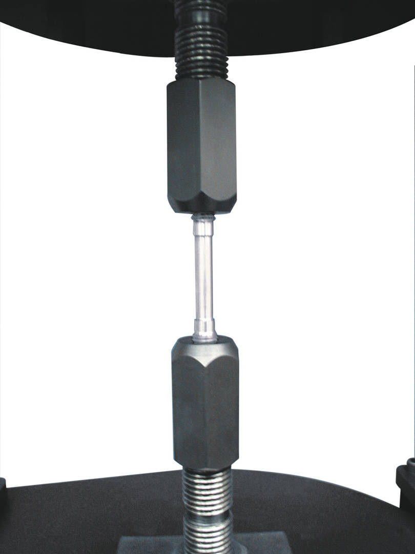
The threaded-end specimen holders are designed to perform static tensile tests on threaded-end specimens to various standards, including ASTM E8 and ASTM A370. The specimen holder has threads on each end: one end threads into an adaptor (purchased separately) connecting it to the frame, and the other end having threads to hold the specimen. With a properly aligned crosshead, the threaded-end specimen holders ensure the specimens are loaded in uniaxial tension. Each set contains 2 threaded-end specimen holders. Capacity 267 kN. Temperature Rating: +5°C to +40°C

Specifications
Description Upper Fitting Specimen Diameter Specimen Thread Size Catalog Number
ASTM Standard .505" 1.5 in-6fRH 12.8 mm (0.505 in) 0.75 in-10fRH W-5101
ASTM Standard .505" M36x4fRH 12.8 mm (0.505 in) 0.75 in-10fRH W-5150
Non-Standard Up to 38 mm (1.5 in) Up to 38 mm (1.5 in) Up to 38 mm (1.5 in) W-5102

Split Insert Tensile Grip Holders and  Inserts
Split Insert Tensile Grip Holders and  Inserts Split Insert Tensile Grip Holders and  Inserts Split Insert Tensile Grip Holders and  Inserts

Shoulder-End and Button-End Specimens Holders and Inserts

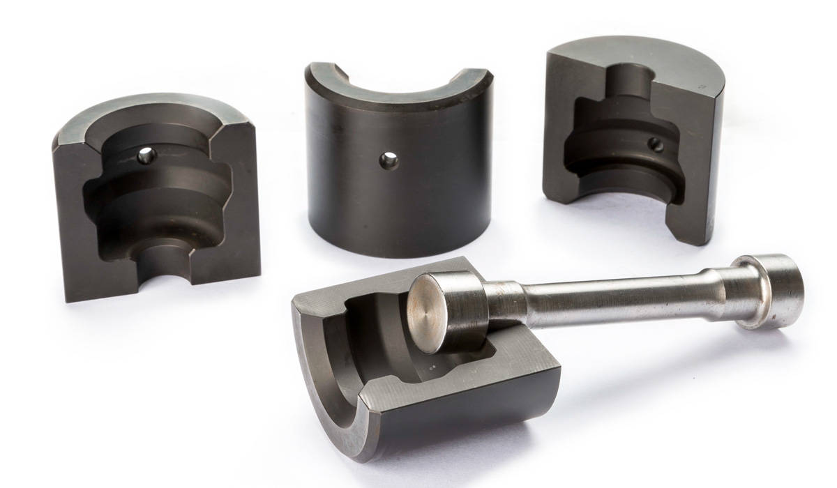
The modular design offers a single set of holders and interchangeable split inserts that match industry standard dimensions for performing tensile testing on shoulder-end and button-end specimens. Each set of insert holders requires at least one set of inserts to perform a test.

Holders
Capacity Mounting Type Effective Length Catalog Number
300 kN Type R4 (M36 × 4p) 83 mm (3.3 in) W-5158-1
300 kN 1.5 - 6 in UNC 83 mm (3.3 in) W-5158-2
300 kN 1.5 - 12 in UNF 83 mm (3.3 in) W-5158-3
600 kN Type II RH
(M48 × 2p RH)
127 mm (5.0 in) W-5159
300 kN Inserts Specifications to ASTM E8, A370 (Requires W-5158 Holders)
Capacity Specimen Reduced Section Diameter Catalog Number
300 kN 12.83 mm (0.505 in) W-5158-A
200 kN 9.07 mm (0.357 in) W-5158-B
150 kN 6.40 mm (0.252 in) W-5158-C
50 kN 4.06 mm (0.160 in) W-5158-D
600 kN Inserts Specifications to ASTM A48 (Requires W-5159 Holders)
Capacity Specimen Reduced Section Diameter Catalog Number
600 kN 31.75 mm (1.25 in) W-5159-A3
500 kN 19.0 mm (0.75 in) W-5159-A2
400 kN 12.7 mm (0.50 in) W-5159-A1

Debris Shields

Debris Shields

Debris shields, also known as protective shields, provide a protective barrier between the test space and the operator. These may be necessary for materials that exhibit violent failures under test, such as composites, rebar, and cables.

Debris shield on floor model universal testing system
Debris shield on floor model universal testing system Debris shield on dual column table model universal testing system Debris shield on single column universal testing system
Debris Shield with Hinged Door for Single Columns, Table Models, and Floor Models


These debris shields feature an anodized extruded aluminum frame and clear Lexan® panels that offer unobstructed views of the text space. A hinged-style access door is available with or without door safety interlocks.

Compatible Frames Catalog Number
Single Columns | 500 N Systems:
334X, 34SC, 594X, 68SC
CP127700
Single Columns | 1 - 5 kN Systems | Standard Height:
334X, 34SC, 594X, 68SC
CP127701
Single Columns | 5 kN Systems| Extra Height:
3345, 34SC-5, 68SC-5
CP127702
Table Models | Standard Width:
336X (dual T-slot column cover style only), 34TM, 446X, 556X, 586X, 596X, 68TM
2910-074
Floor Models:
3382, 3384, 3385H, 34FM, 4481, 4482, 4484, 4485, 5581, 5582, 5584, 5585, 5585H, 5881, 5882, 5884, 5885, 5885H, 5982, 5984, 5985, 5985, 68FM
2910-062

Contact Us For Details

34TM-with-Sliding-Debris-Shield
34TM-with-Sliding-Debris-Shield Operator-Sliding-Debris-Shield
Debris Shield with Sliding Door for Table Models


Depending on user-preference and footprint limitations, a sliding debris shield is available for table model universal testing systems. The sheet metal and polycarbonate shield encase the front of the test machine, separating the user from debris and moving parts while also giving excellent visibility. To access the test space, the sliding door is opened to the left and specimens and grips can be loaded through the 845mm tall and 440mm wide port. The debris shield can be equipped with an optional magnetic interlock which prevents tests from being started with the door open and can be configured to prevent all crosshead motion when the door is open.

Compatible Frames Catalog Number
68TM, 34TM, 336X, 596X | Standard Height, Standard Width CP129040
68TM | Extra Height, Standard Width CP129044
34TM, 336X, 596X | Extra Height, Standard Width CP126003
336X, 596X | Standard Height, Standard Width CP126002

Contact Us For Details

Component Test Plate

COMPONENT TEST PLATE

For Testing End Products and Components

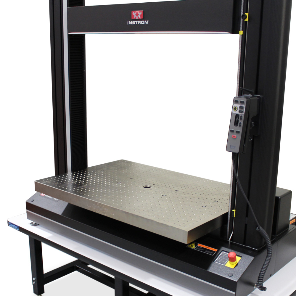
Component Test Plate

The Component Test Plate is a drilled and tapped metal plate that can be mounted directly to the base of single and dual column test frames. The entire surface is covered in an array of M6 threaded holes that can be used for a variety of purposes, including mounting components or end products to the plate for tensile, compression, bend, peel, or puncture testing. The plate also allows you to mount grips off-center and makes it easier adapt custom-made grips and fixtures to your test system.
Request A Quote


Principle of Operation

Components or end products can be mounted directly to the component test plate with compatible M6 hardware or machinist vices. The location of the specimen on the plate should be selected such that the area of interest, where the load application occurs, is completely centered. If the load application is off-center it could potentially damage the load cell.

The component test plate is also compatible with Instron standard base adapters (type O and D) which can be mounted to the plate using any of the M6 threaded holes – allowing you to place a grip off-center or adapt a custom-made grip or fixture to the test frame.

Application Range

  • Test types: tensile, compression, flexure, peel, puncture
  • Common applications: biomedical, electronics, microelectronics, consumer products


Component Test Plate on 68TM Universal Testing System
Component Test Plate on 68TM Universal Testing System Keyboard Button Compression Testing Biomedical Specimen on Component Test Plate Component Test Plate on Extra Wide 6800 Series Universal Testing System
Specifications
Catalog no. Compatible Frames Capacity Width  Depth
2910-108 Single Column Systems
68SC
1 kN 600 mm 300 mm
2910-107 Dual Column Systems
68TM, 34TM, 596x, 336x, 556x, 556xA, 446x
2 kN 300 mm 300 mm
2910-106 Single Column Systems
334x
1 kN 600 mm 300 mm
2910-105 Single Column Systems
34SC, 594x, 554x
1 kN 600 mm 300 mm
CP129729 Extra Wide Dual Column Systems
68TM-30
30 kN 914 mm 610 mm
CP129738 Dual Column Systems
68TM, 34TM, 596x, 336x, 556x, 556xA, 446x
30 kN 400 mm 400 mm