AVE2 Advanced Video Extensometer

AVE2 Advanced Video Extensometer

Non-Contacting Strain Measurement for Dynamic and Fatigue Testing

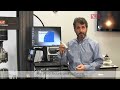
The Instron AVE2 Advanced Video Extensometer delivers the accuracy and consistency of non-contacting video extensometry in a lightweight, portable design purpose-built for dynamic and fatigue testing. In addition to excellent performance for static testing, the AVE2 is rated for cyclic testing and high-speed monotonic measurement — making it the ideal single strain measurement solution for laboratories running both static and dynamic test programs.

Designed to move easily between systems, the AVE2 can be deployed across multiple Instron ElectroPuls® and servohydraulic testing systems in the same laboratory, offering scientists, engineers, and quality specialists the flexibility to study dynamic material behavior without contacting or influencing the specimen.
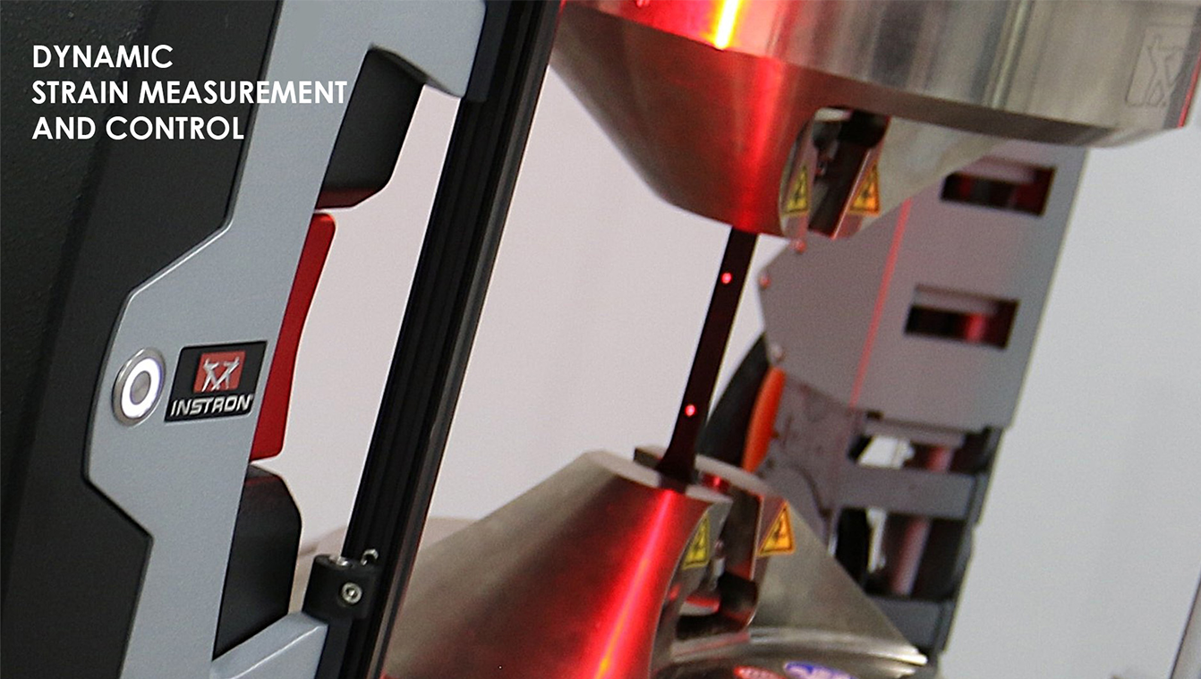
Dynamic Strain Measurement and Control - Instron Non-Contacting Video Extensometer

Dynamic Testing Specifications

Cyclic testing frequencies up to 20Hz

Cyclic testing frequencies up to 20Hz

#image_title

Dynamic axial field view of up to 240mm

High Resolution

Resolution and accuracy as low as 2 microns

Displacement Tracking

Displacement tracking up to 500mm/s

490Hz Data Acquisition Rate

Real-time data acquisition rate of 490Hz/s

Key Technologies

CDAT Airflow Technology (Patented)

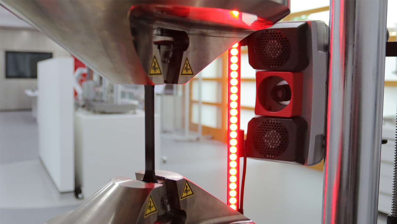
Typical laboratory environments are subject to variations in airflow — from HVAC systems, nearby equipment, and normal laboratory activity — that can introduce measurement errors of several microns. To maximize accuracy in real-world test conditions, the AVE2 uses Instron's patented Constant Density Air Tunnel (CDAT) technology. CDAT fans generate a consistent laminar airflow between the specimen and camera, shielding the optical path from environmental disturbances and producing consistent results even when air conditioning or ventilation systems are active during a test.
Cross-Polarized Lighting System (Patented)

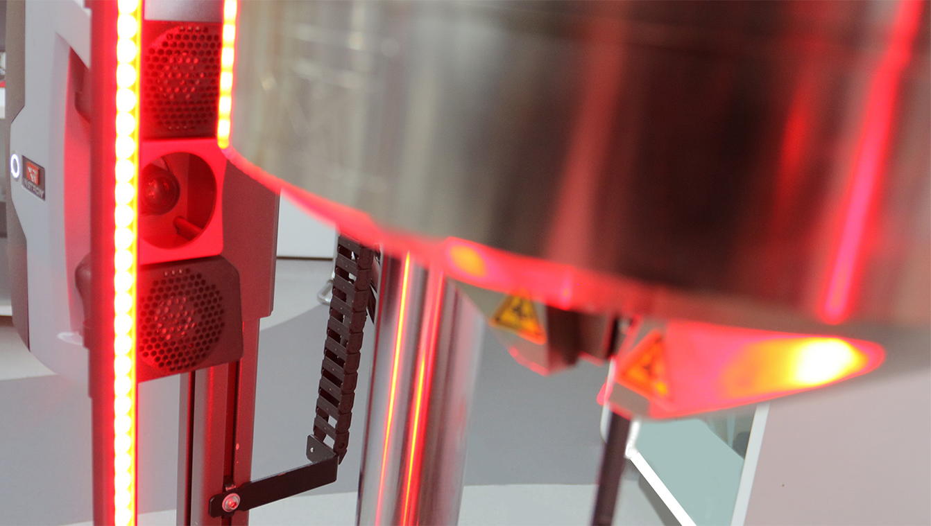
Lighting conditions vary between laboratories and change throughout the day — both of which can introduce variation into extensometer results for the same test type. The AVE2 uses Instron's patented cross-polarized lighting system to ensure the camera always captures a consistent image of the specimen markings, regardless of ambient light conditions. This delivers repeatable results across different shifts, operators, and laboratory environments.
Non-Contacting Measurement

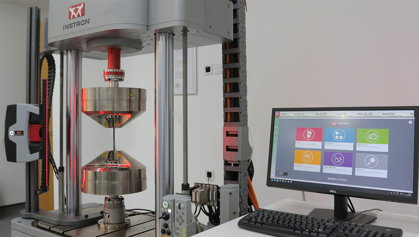
By measuring strain without physical contact with the specimen, the AVE2 eliminates the negative effects of device attachment on test results — including premature specimen damage, attachment variability between operators, and the risk of shock loading damage during high-energy specimen failures. The result is strain data that is inherently more consistent, accurate, and repeatable across the full life of the device.

Flexibility Across Applications

The AVE2 is compatible with a range of environmental chambers, bio-baths, and optional lenses — making it suitable for testing across a wide range of temperatures, environments, and specimen geometries. A single AVE2 can accommodate specimens with multiple gauge lengths and elongation ranges, replacing the need for multiple clip-on devices and simplifying both inventory management and operator training.

In addition to tensile and compression testing, the AVE2 enables measurement and closed-loop control of cyclic strain on a wide range of materials and specimen types — from metals and composites to elastomers, biomaterials, and films.

Compatible with Bluehill® Universal software for static testing and WaveMatrix3 for dynamic and fatigue testing, the AVE2 integrates directly into Instron's testing software environment for seamless data acquisition and test control.
Compatible Testing Systems
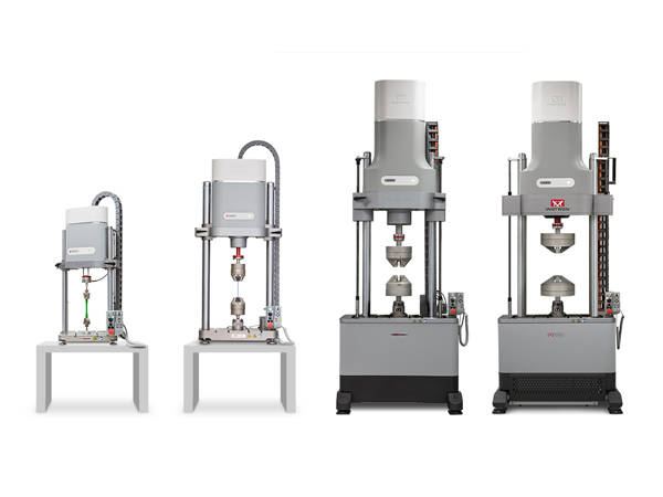
Linear electric motor driven dynamic test machines for fatigue and fracture mechanics testing.
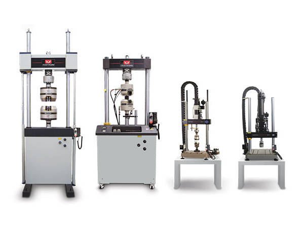
General purpose servohydraulic systems ideal for high-cycle and low-cycle fatigue, fracture mechanics and quasi-static testing.

Talk to an Instron Expert

Whether you are evaluating the AVE2 for a new dynamic testing program or looking to add non-contacting strain measurement capability to an existing system, our team can help you find the right configuration for your application.

Contact Our Sales Department.

Please complete the form below and we will be happy to contact you with a response. Our typical response time for an online request is within 1-2 business days. For a faster response, please call +1-800-473-7838.


Please close this window and accept cookies to view and fill out the form.

AutoX750 Automatic Contacting Extensometer

AUTOX750

Automatic Contacting Extensometer

The need for companies to increase specimen throughput — while maintaining high quality standards and safe operating conditions — has created demand for greater speed, reliability, and accuracy in material testing routines. The AutoX750 is an automated long-travel extensometer built to meet that demand with sub-micron precision. With automated gauge length positioning and attachment to the test specimen, operators get a safer, simpler test routine — and companies get faster cycle times while eliminating the variability that comes with manual, time-consuming steps of traditional clip-on extensometers.

Contact Our Sales Department.

Please complete the form below and we will be happy to contact you with a response. Our typical response time for an online request is within 1-2 business days. For a faster response, please call +1-800-473-7838.


Please close this window and accept cookies to view and fill out the form.
AutoX750 Automatic Contacting Extensometer for Testing Plastics

Principle of Operation

The AutoX750 integrates with Instron's 3360, 3380, 3400, 5500, 5960, 5980, and 6800 Series electromechanical test systems, as well as LX, DX, HDX, and KPX static hydraulic testing systems, and is controlled with Bluehill® Universal testing software via USB interface. The software drives an easy-to-use test sequence and setup that facilitates the automated gauge length, reference arm position and opening and closing of the arms before and after testing.

The counterbalanced measuring arms are virtually weightless, thus removing any influence on the material properties under test. The measuring arms are motor driven and will automatically position themselves to the correct position and gauge length every time.

In Bluehill Universal, the AutoX750 provides:

  • Real-time strain data streamed directly into the test method
  • Automated modulus, offset yield, and elongation calculations
  • Logged gauge length and arm position for full test traceability

Application Range

  • Tensile testing: metals, composites, plastics, and elastomers
  • Flexure testing: plastics
  • Specimen shapes: strip, round, hexagonal, and flat
  • Standard compliance: Conforms to the most rigorous testing standards, including:
AutoX750 Automatic Contacting Extensometer
  1. High Travel - With high accuracy and resolution across 750 mm of travel, the AutoX750 suits a wide range of specimen sizes and gauge lengths.
  2. Counterbalance Technology - Proven counterbalanced technology eliminates external influences on the material under test, producing highly repeatable and reliable measurements.
  3. Automated Test Arms - Built for simplified, safer test routines, reduced cycle time, and high reproducibility. The automated arms attach to the specimen and can remain attached through failure for most materials.
  4. Interchangeable Knife Edges - Swappable knife edges and adjustable clamping forces accommodate a variety of materials and specimen geometries.

Endless Applications

The AutoX750's accuracy and travel make it suited to nearly any material — metals, plastics, and composites alike. Use it to determine modulus, offset yield, non-proportional plastic elongation to failure, and r- and n-values for sheet metals.

AutoXBiax — Axial and Transverse Strain Measurement

Catalog No. 2665-751

The AutoXBiax is an automated, high-precision measurement device that captures axial and transverse strain simultaneously. Built on the same high-accuracy optical measurement system as the AutoX750, it's purpose-designed to measure plastic strain ratio (r-value) for steel — exceeding current standards including ISO 10113, ASTM E517, and JIS Z 2254.

The AutoXBiax is compatible with the 3382A, 5960, 5980, and 6800 Series systems.

AutoX750 vs. AutoXBiax — Which Do I Need?
AutoX750 AutoXBiax
Strain Measured: Axial only Axial and transverse (simultaneously)
Best For: General tensile/flexure testing across metals, plastics, composites, elastomers r-value determination for sheet steel
Key Standards: ISO 527-2, ASTM D638, ISO 6892-1, ASTM E8, ASTM D3039 ISO 10113, ASTM E517, JIS Z 2254
Compatible Frames: 3360, 3380, 3400, 5500, 5960, 5980, 6800 Series; LX, DX, HDX, KPX 3382A, 5960, 5980, 6800 Series

If your test standard calls for an r-value or you need transverse strain alongside axial, the AutoXBiax is the fit. For general-purpose tensile and flexure work, the AutoX750 covers the broader range of materials and frame compatibility.

Talk to an Instron Expert.

Not sure whether the AutoX750 or AutoXBiax fits your application, or need help matching gauge length, knife edges, and frame compatibility to your test standard? Tell us about your specimens and testing requirements and we will help you find the right solution.

Contact Our Sales Department.

Please complete the form below and we will be happy to contact you with a response. Our typical response time for an online request is within 1-2 business days. For a faster response, please call +1-800-473-7838.


Please close this window and accept cookies to view and fill out the form.

AlignPRO Alignment System

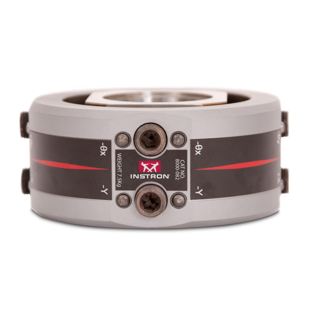
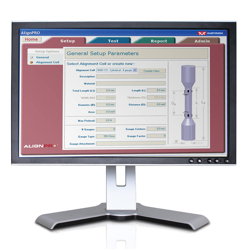
For applications with specific alignment requirements, the AlignPRO™ system can be used to control both concentricity and angularity in your load string to optimize alignment. The system consists of an AlignPRO Fixture, mounted between the load cell and the load frame, which is used to make adjustments to concentricity and angularity.

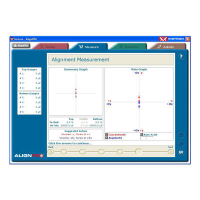
AlignPRO Software monitors the output from strain gauges mounted on either flat or round alignment cells. These outputs are used to calculate bending due to angular and concentric alignment errors, so you can make adjustments with the AlignPRO Fixture while monitoring their effect on bending in real time.

Need to verify alignment to ASTM E1012 or Nadcap requirements? Instron also offers alignment verification services.

Use the links below to jump directly to the section you are interested in:

AlignPRO Fixtures | AlignPRO Software | Strain-Gauged Alignment Cells

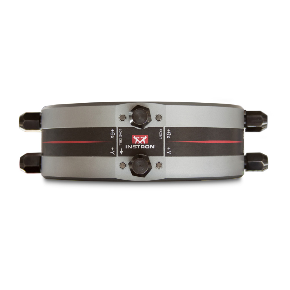
AlignPRO Fixture 8000-082
AlignPRO Fixture 8000-082 AlignPRO Fixture 8000-084

AlignPRO Fixtures

The AlignPRO Fixture allows the load cell and grip assembly to be aligned quickly and precisely. Both concentric and angular misalignment can be adjusted while the load string is still preloaded.

Catalog No. Description
2910-130 For 100 kN (22 kip) Electromechanical Machines
2910-132 For 150 and 250 kN (34 and 56 kip) Electromechanical Machines
8000-082 For Dynamic Machines — Capacities up to 250 kN (56 kip)
8000-084 For Dynamic Machines — Capacities up to 500 kN (112 kip)

AlignPRO Software
AlignPRO Software AlignPRO Software

AlignPRO Software and Electronics

When used with the Instron® AlignPRO Fixture, AlignPRO Software identifies which adjustments are required and displays the effect of each adjustment in real time, enabling accurate machine setup for optimal alignment in just a few minutes.

AlignPRO Software combines the strain signals from an alignment cell and presents misalignment information both numerically and graphically on screen. The strain readings update constantly, so adjustments made with the optional AlignPRO Fixture can be read immediately.

Strain Gauged Alignment Cell
Strain Gauged Alignment Cell Strain Gauged Alignment Cell

Strain-Gauged Alignment Cells

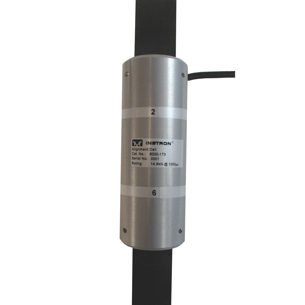
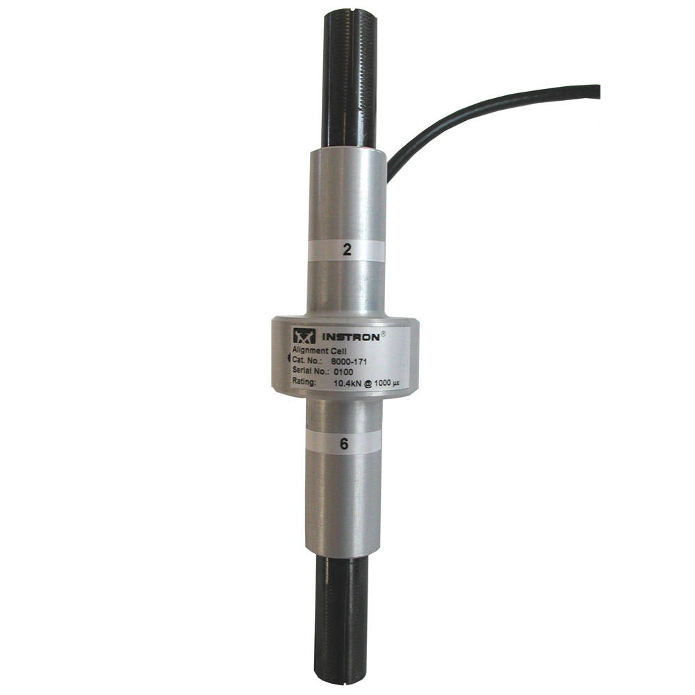
When a strain-gauged alignment cell is installed in the grips, any misalignment in the load string causes the alignment cell to bend. The electronics supply each strain gauge with a stable reference voltage, and each strain gauge output is fed back to a data acquisition unit and made available to AlignPRO Software as a real-time strain signal.

Catalog No. Description
8000-171 Strain-Gauged Alignment Cell, 8 Gauges, 8 mm Diameter in Gauged Section
8000-172 Strain-Gauged Alignment Cell, 8 Gauges, 10 mm Diameter in Gauged Section
8000-173 Strain-Gauged Alignment Cell, 8 Gauges, Flat 12 mm x 6 mm in Gauged Section
8000-174 Strain-Gauged Alignment Cell, 8 Gauges, Thin Flat 15 mm x 2 mm in Gauged Section

Talk to an Instron Expert

Not sure which AlignPRO components fit your testing system or alignment requirements? Tell us about your setup and we will help you find the right solution.

Talk to an Applications Engineer

Tell us about your testing needs, and we'll help you configure the right frame, load cell, grips, and software for your lab. Please complete the form below, and we'll respond within 1-2 business days. For a faster response, call +1-800-473-7838 or +1 781 828 2500 if you are outside of the US.


Please close this window and accept cookies to view and fill out the form.

Hydraulic Side Action Tensile Grips

HYDRAULIC SIDE ACTION TENSILE GRIPS

With a Patented Self-Centering Mechanical Synchronizer

Hydraulic Side Action Tensile Grip

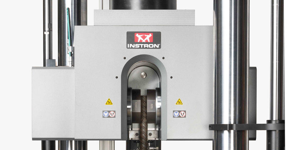
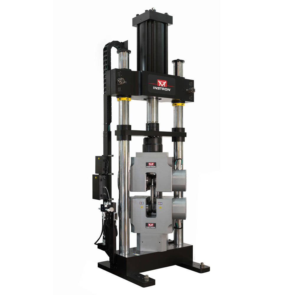
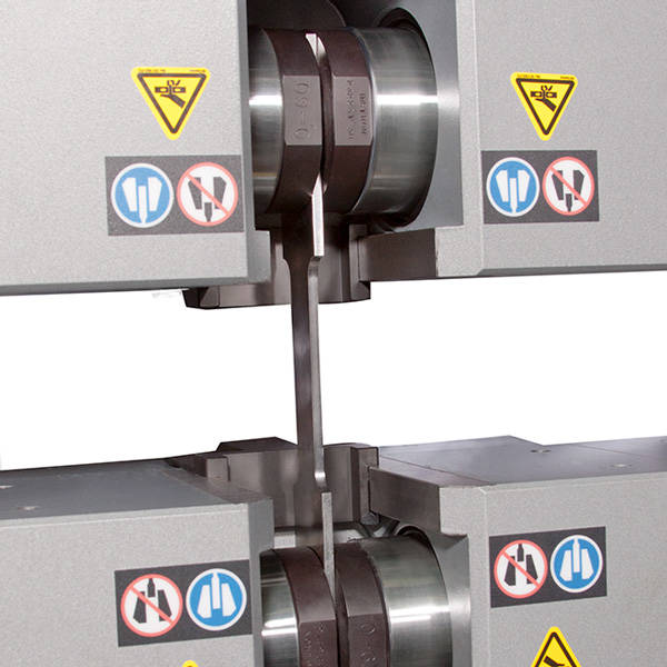
Instron hydraulic side acting grips provide an innovative solution for high-capacity testing and deliver enhanced gripping performance, usability, and operator safety over traditional grip designs. These advanced grips maintain a constant clamping force on the specimen that acts perpendicular to the direction of testing and is independent of tensile loading.

Contact Our Sales Department

Please complete the form below and we will be happy to contact you with a response. Our typical response time for an online request is within 1–2 business days. For a faster response, please call +1-800-473-7838.


Please close this window and accept cookies to view and fill out the form.

PATENTED DURASYNC TECHNOLOGY

Hydraulic Side Action Grip with Operator

SUPERIOR GRIPPING PERFORMANCE

Instron’s dual side-acting grips incorporate our latest DuraSync technology. This patented self-centering mechanical synchronizer provides many improvements over hydraulic or mechanical rack and pinion designs commonly found in the marketplace.

  • Side-load dampening reduces the risk of grip damage when testing slightly bent or irregularly shaped specimens such as rebar or wire rod
  • Opposing jaw faces repeatedly self-center during specimen clamping reducing testing time and eliminating the need to resynchronize the grip faces between tests
  • The synchronizer is located outside the gripping pocket preventing mechanical failure due to contamination

Features

  • Adjustable clamping force alleviates specimen slippage and grip breaks
  • Operator safety is improved through the use of low-pressure (131 bar) external supply lines
  • Hydraulic power is provided by the machine’s main power supply reducing the cost and floor space associated with a secondary grip pumping unit  Note: For static electromechanical systems, a low-pressure, standalone pump is required.
  • Fully open-front design provides easy specimen insertion increasing testing efficiency and safety
  • DuraSync 2 offers semi-open back design which facilitates testing of shorter specimen when using an automatic extensometer
  • Jaw faces are easily installed from the front side of grips and require no maintenance beyond simple cleaning
  • Ergonomic control handset includes user-friendly, 3-position switches for upper and lower grip operation, and a magnetic back adding to operator convenience and productivity
  • Grips are field-serviceable reducing down time and eliminating the cost of sending the grips back to the factory for service

Application Range

  • Tensile tests on a wide range of materials including: steel rod and plate, machined rounds and flats, reinforcement bar, 3- and 7-wire strand, conveyor belt, and wood products
  • Tension-tension cyclic tests
  • Compression testing using optional secondary load string adapter
  • Low-frequency, thru-zero cyclic testing with thru-zero support option
1500 kN KPX with Hydraulic Side Action Grips
1500 kN KPX with Hydraulic Side Action Grips 2000 kN Hydraulic Side Action Grips Hydraulic Side Action Grips on KPX Hydraulic Side Action Grips Testing Flat Specimen
Specifications
Catalog No. Force Capacity Operation   Specimen Range
Rounds Flats Cable
W-5450 250 kN Dual Side-Acting Standard 3 – 60 mm 0 – 60 mm –
W-5400 600 kN Single Side-Acting Standard 3 – 57 mm 0 – 75 mm –
W-5410 600 kN Dual Side-Acting Standard 3 – 60 mm 0 – 100 mm –
W-5420 600 kN Dual Side-Acting Premium  Premium Model
The premium grips can be configured for testing standard flat, round, wire strand, and cable specimens. This model can also be configured for thru-zero (negative load) testing, provided the load frame is capable of thru-zero (cyclic) loading.
3 – 60 mm  Thru-Zero Specimen Range: 3 – 60 mm 0 – 100 mm  Thru-Zero Specimen Range: 0 – 75 mm 4.8 – 25.4 mm
W-5460 1000 kN Dual Side-Acting Premium  Premium Model
The premium grips can be configured for testing standard flat, round, wire strand, and cable specimens. This model can also be configured for thru-zero (negative load) testing, provided the load frame is capable of thru-zero (cyclic) loading.
3 – 85 mm 0 – 120 mm 4.8 – 25.4 mm
W-5430 1500 kN Dual Side-Acting Premium  Premium Model
The premium grips can be configured for testing standard flat, round, wire strand, and cable specimens. This model can also be configured for thru-zero (negative load) testing, provided the load frame is capable of thru-zero (cyclic) loading.
3 – 85 mm  Thru-Zero Specimen Range: 3 – 85 mm 0 – 120 mm  Thru-Zero Specimen Range: 0 – 85 mm 4.8 – 25.4 mm
W-5440 2000 kN Dual Side-Acting Premium  Premium Model
The premium grips can be configured for testing standard flat, round, wire strand, and cable specimens. This model can also be configured for thru-zero (negative load) testing, provided the load frame is capable of thru-zero (cyclic) loading.
3 – 100 mm  Thru-Zero Specimen Range: 3 – 85 mm 0 – 120 mm  Thru-Zero Specimen Range: 0 – 85 mm 4.8 – 25.4 mm

Electromechanical Frame Accessories

Electromechanical Frame Accessories

Enhance the performance, versatility, and safety of your universal testing system with our range of electromechanical load frame accessories, attachments, and upgrades. These system enhancements expand the safety and testing capabilities of your Instron 6800 and 3400 Series load frame — as well as select out-of-production models, including the 3300 and 5900 Series — supporting a wider range of testing applications.

Debris shield on floor model universal testing system
Debris shield on floor model universal testing system Debris shield on dual column table model universal testing system Debris shield on single column universal testing system

Debris Shields

Debris shields provide a protective barrier between the test space and the operator. These may be necessary for materials prone to sudden or high-energy failure under test, such as composites, rebar, and cables.

A heavy duty support table capable of supporting Instron table model testing systems.
A heavy duty support table capable of supporting Instron table model testing systems. An Instron 68TM Universal Testing System shown on the heavy duty support table.

Heavy-Duty Support Tables

Catalog Number 2910-056

The heavy-duty load frame support table provides a stable, level working surface for dual-column electromechanical tabletop load frames. It distributes the frame's weight evenly, improves operator safety, and creates a more ergonomic working height for users.

Test machine operator inserts plastic specimen into Instron pneumatic side action tensile grips mounted on 68TM universal testing system with Bluehill Universal software and Advanced Video Extensometer.
Test machine operator inserts plastic specimen into Instron pneumatic side action tensile grips mounted on 68TM universal testing system with Bluehill Universal software and Advanced Video Extensometer. Operator activates footswitch to actuate pneumatic powered tensile grips. Back of system view of 68SC universal testing system showing air kit connection point for pneumatic powered accessories.

Air Kits for Pneumatic Grips

Pneumatic air kits, footswitches, and distribution kits are available to support easy grip closure and a streamlined specimen loading process, boosting operator productivity with pneumatic grips, including pneumatic side-acting tensile grips, pneumatic cord and yarn tensile grips, pneumatic peel fixtures, and more.

Instron 68TM universal testing machine with a compact hydraulic grip pump sitting on the tabletop supplying power to advanced hydraulic wedge grips.
Instron 68TM universal testing machine with a compact hydraulic grip pump sitting on the tabletop supplying power to advanced hydraulic wedge grips. Instron floor-standing hydraulic grip pump for supplying power to hydraulic wedge and side action tensile grips. Instron 6800 Series Floor Model Universal Testing System configured with advanced hydraulic wedge grips powered by floor standing hydraulic grip pump - also configured with Advanced Video Extensometer installed on the outside of an environmental chamber for non-ambient testing.

Hydraulic Grip Pump

Hydraulic grip pumps deliver precise, reliable clamping force for Instron's hydraulic grips, with front‑mounted analog gauges for easy monitoring. Choose from a compact pump for wedge grip applications or a floor‑standing model compatible with both wedge and side‑acting grips.

Close up view of a digital I/O board that can be used with Instron universal testing systems.
Close up view of a digital I/O board that can be used with Instron universal testing systems. Instron's Expansion Channel Module that allows for up to eight channels of signal conditioning and control.

Digital Controller Accessories

Instron universal testing systems support a broad range of sensor conditioning modules and Analog Output and Digital Input/Output boards, enabling seamless interfacing with external equipment and measuring devices.

Talk to an Instron Expert

Not finding the accessory you're looking for? Instron has produced thousands of custom accessories, many of which never make it onto our website. Tell us about your application, and we'll help you find the right solution.

Contact Our Sales Department.

Please complete the form below and we will be happy to contact you with a response. Our typical response time for an online request is within 1–2 business days. For a faster response, please call +1-800-473-7838.


Please close this window and accept cookies to view and fill out the form.
Screw Side Action Tensile Grips

SCREW SIDE ACTION TENSILE GRIPS

For Tensile Testing on a Wide Range of Materials and Specimen Types

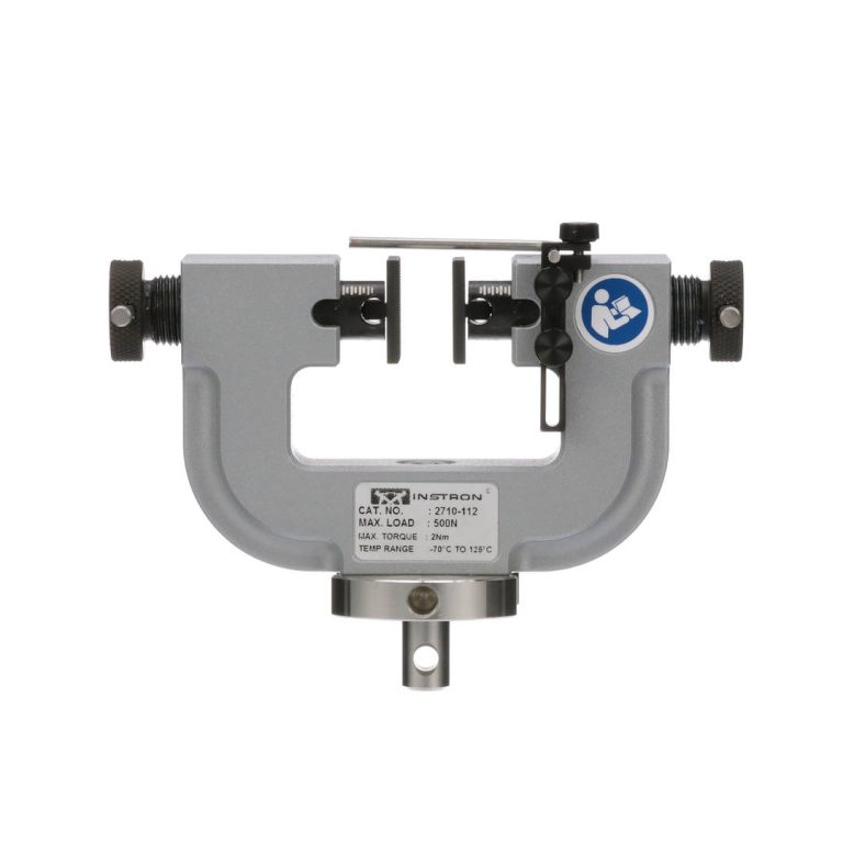
2710-100 Series Advanced Screw Side Action Grips

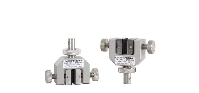
Screw action grips provide a very simple and efficient method for holding test specimens in a wide range of applications. The dual-acting design means that jaw faces can be adjusted to accommodate different specimen thicknesses, this ensures that the line of tensile force remains concentric with the grip body. They can be equipped with a selection of interchangeable grip jaw faces in various sizes and choice of surfaces including smooth ground, rubber-coated, and serrated.

ADVANCED SCREW SIDE ACTION TENSILE GRIPS

2710-100 Series | 100 N - 10 kN Force Capacities

Principle of Operation

The 2710-100 Series dual-acting screw design accommodates specimens up to 46 mm (1.8 in) thick and can be offset for irregular or asymmetrical specimens such as lap-shear types and component testing. Screw knobs on either side are knurled to facilitate hand tightening and the higher capacities also feature hex socket screw knobs that accommodate a hex key or torque wrench. Engraved scales on the carriages aid in centering the planes of gripping.

Application Range

  • Type of loading: tensile, static and tension-tension cyclic tests - not suitable for high cycle dynamic fatigue tests
  • Specimen materials: plastics, metals, textiles, paper, thin sheet, foil, wire, etc.
  • Specimen shapes: components, round (wires), and flat specimens with or without shoulder
Force Capacity Catalog no.
100 N 2710-111
500 N 2710-112
1 kN 2710-113
2 kN 2710-114
5 kN 2710-115
10 kN 2710-116

KEY FEATURES

Advanced Screw Side Action Grips

2710-112-03-12

Quick Change Jaw Faces
The quick change jaw face design allows all jaw faces to be changed single-handedly in seconds without the use of tools or pins.
 

Designed to Ease Alignment
Carriages with engraved scales ease alignment of specimens to the axis of testing. Self-aligning jaw faces compensate for specimen irregularities. Optional specimen alignment devices increases repeatability by helping operators load the specimen in the center of the grips.
 

Versatile
Wide opening suitable for a wide range of specimen thicknesses and unique components. Large space between the jaw faces and the grip body eases specimen insertion.
 

Wide Range of Jaw Faces
Available in rubber-coated, serrated, smooth-ground, brake-lining (HFC), line-contact, wave-profile, and vee-serrated.
 

OTHER MODELS
Mid-Range and Low-Force Grips

Basic Mid-Range Grips
2710-200 Series | 1 kN - 5 kN Force Capacities

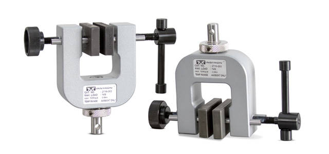
2710-200 Series screw side action grips are designed for basic mid-force-range static tensile testing on a wide range of materials.

View Specifications

Basic Low-Force Grips
2710-004 | 500 N Force Capacity

2710-004 screw side action grips are designed for basic static tensile testing for low-force applications.

View Specifications

Mechanical Wedge Action Grips

MECHANICAL WEDGE ACTION TENSILE GRIPS

For Tensile Testing on a Wide Range of Materials and Specimen Types

Manual Wedge Action Grips

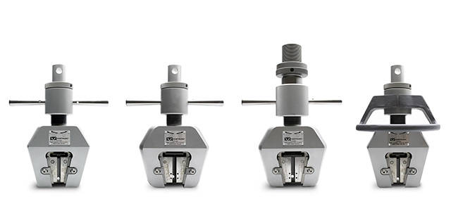
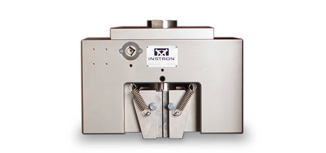
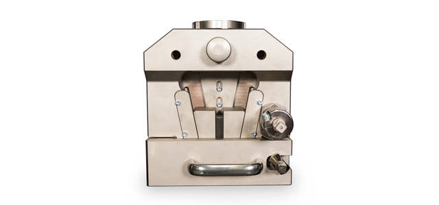
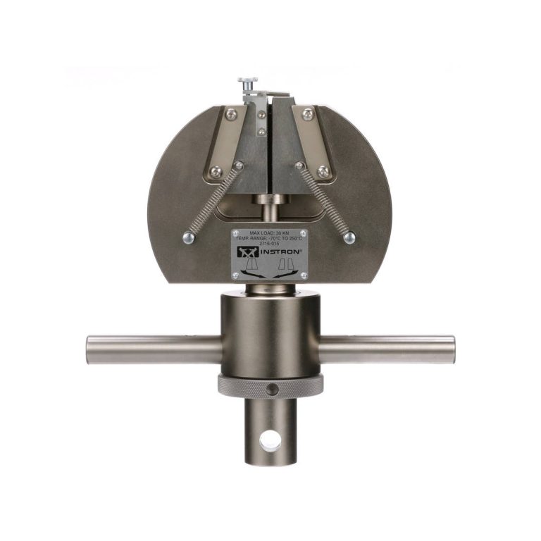
The manual wedge action grip is designed for easy specimen loading, alignment, and positioning. After initial specimen contact, gripping force increases as the testing load increases. Virtually no preload is seen during specimen clamping due to the design of the moving grip bodies, making them particularly suitable for testing high strength materials, such as metals and composites, ensuring that specimen slippage is eliminated.

AVAILABLE MODELS

1 kN - 150 kN Force Capacities

Low-Force Grips
1 kN - 50 kN Force Capacities

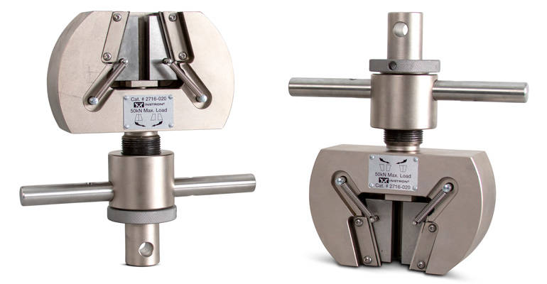
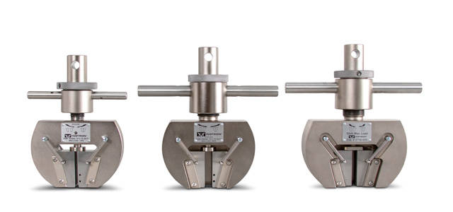
The low-force 2716 Series wedge grips are ideal for static tensile testing on a wide range of materials including plastics, elastomers, and metals.

View Specifications    View Jaw Faces

High-Force Grips
100 kN and 150 kN Force Capacities

The high-force range of 2716 Series wedge grips are ideal for static tensile testing on metal and composite material.

View Specifications    View Jaw Faces

Principle of Operation

The wedge action principle of these grips allows them to be tightened onto a specimen without altering the vertical position of the faces in relation to the specimen. This is accomplished by a design, which moves the grip body to close the faces. This feature makes it possible to pre-select the exact point at which the specimen will be held with consistent gauge length and no compressive force applied which may cause specimen buckling.

A strong clamping force can be applied to materials that are difficult to hold through a high mechanical advantage achieved by the tightening mechanism. The grip faces are spring loaded against a shoe which is in a fixed position in respect to the testing frame holding mechanism, only a light initial gripping force needs to be applied to the specimen. As the grip is tightened, it's frame is drawn up and the inclined sides push against the matching side of the faces which move laterally against the specimen. A shoe incorporated to the driving shaft prevents the faces from moving.

The open front design of the grip frames allows faces to be easily interchanged as well as easy specimen loading. Because the faces are held in fixed position, there is no recoil, or loosening, when the specimen ruptures and if an extensometer is attached, it will remain in place.


2716-015-01-08


Catalog no. 2716-015
68TM-502716-020-V1-02-14


Catalog no. 2716-020
2716-002-V1-03-13


Catalog no. 2716-002


Features

  • Quick set-up with rapid clamping and unclamping action
  • Easy specimen loading for increased productivity
  • Self-tightening wedge design eliminates slippage
  • Fixed faces and moving body during specimen loading
  • Variety of jaw face sizes and surfaces available
  • Quickly change faces without tools
  • Options for testing conditions up to 350°C (660°F)

Application Range

  • Type of loading: tensile, static and tension cyclic tests
  • Not suitable for high cycle fatigue tests
  • Specimen materials: wires, plastics, metals, elastomers, and composites
  • Specimen shapes: flat or round specimen with or without shoulder tab ends


Available Models
Force Capacity Maximum Specimen Width Catalog No.
1 kN 19 mm 2716-016
2 kN 19 mm 2716-017
5 kN 25 mm 2716-010
30 kN 25 mm 2716-015
30 kN [High Temperature] 25 mm 2736-015
50 kN 25 mm 2716-020
100 kN 25 mm 2716-002
100 kN 50 mm 2716-003
100 kN [High Temperature] 25 mm 2736-004
100 kN [High Temperature] 50 mm 2736-005
150 kN 50 mm 2716-008


OTHER MODELS
For High Force Testing

Precision Manual Wedge Grip

Precision Mechanical Wedge Grips
250 kN Force Capacity
Catalog no. 2716-030

Tensile grips for composites and metals provide accurate, repeatable specimen alignment and are engineered to meet Nadcap AC7122‑1 and AC7101 requirements. Their precise clamping and robust design help ensure reliable, high‑quality test results for demanding applications.

Learn More

2710-004 Screw Side Action Grips

High Capacity Wedge Action Tensile Grips
300 kN Force Capacity
Catalog no. CP130950

Manual wedge grips provide a high‑capacity gripping solution without the need for pneumatic or hydraulic actuation. Their self‑tightening design increases clamping force as load rises, offering reliable, low‑maintenance performance for a wide range of materials and test applications.

Learn More

Self-Tightening Eccentric Roller Tensile Grips

SELF-TIGHTENING ECCENTRIC ROLLER TENSILE GRIPS

For Tensile Testing Thin Sheets, Films, Flexible Plastics, Rubber, and Elastomers

#image_title

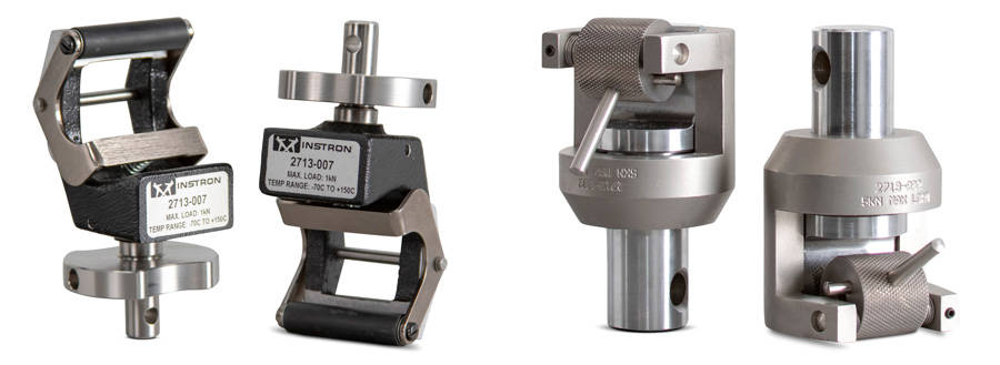
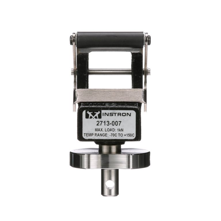
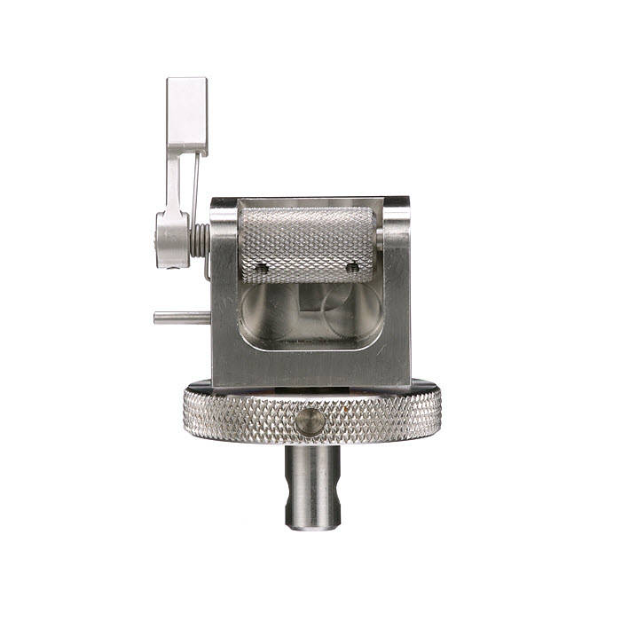
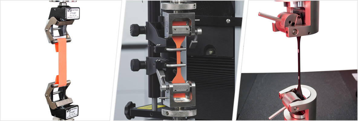
The self-tightening grips are primarily designed for the precision testing of elastomeric and other flexible materials exhibiting a large reduction in cross-section area under load. They provide excellent testing accuracy, positive non-slip gripping action and are quick and simple to use. The upper grip is counter balanced so that the specimen can be aligned with the load cell to eliminate non-axial forces.

AVAILABLE MODELS

1 kN - 5 kN Force Capacities

2713-007-01-02

1-kN-Modell | 2713-007

2713-004-01-18

2-kN-Modell | 2713-004

2713-002-01-01

5-kN-Modell | 2713-002

Principle of Operation

The self tightening grip uses an eccentric roller type clamping action. A single fast action lever reduces the time required to load specimens. Specimen insertion is extremely easy and the spring pressures of the roller bracket gives a positive non-slip action gripping force. This is sufficient to hold the material until a load is applied. The follow up action of the roller while under test prevents the specimen from slipping out of the grip as the load increases.

Specimen Loading: 1 kN Grips

Specimen Loading: 2 kN Grips

Application Range

  • Type of loading: tensile, static, and tension cyclic tests - not suitable for high cycle dynamic fatigue tests
  • Specimen materials: thin sheets, films, flexible plastic and elastomers
  • Specimen shapes: flat specimen with or without shoulder tab ends
Specifications
Catalog no. 2713-007 2713-004 2713-002
Force Capacity 1 kN 2 kN 5 kN
Maximum Specimen Width 43 mm 28 mm 28 mm
Temperature Range -70 °C to 150 °C -70 °C to 315 °C -70 °C to 315 °C
View Full Specifications Download Brochure Download Brochure Download Brochure

KEY FEATURES

Self-Tightening Eccentric Roller Grips

self-tightening-eccentric-roller-tensile-grips.jpg

Quick Loading

Fast action for rapid specimen insertion to increase testing throughput.

Non-Slip Grip

Positive, non-slip gripping action for accurate results.

Eccentric Roller

Eccentric roller type clamping action increases clamping force with applied force.

Ambient and Non-Ambient Testing

Designed for use in -70° C to 315° C (-94° F to 600° F) temperature ranges.

OTHER MODELS

Low-Force Grips

Thin Film Grips

2713-006 Series | 100 N Force Capacity
 

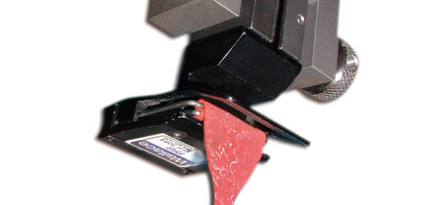
These grips are ideal for tensile testing natural rubber latex, elastomers, paper, and polymer films.

Dynamic Strain Gauge Extensometer

Dynamic Strain Gauge Extensometer

2620 Series

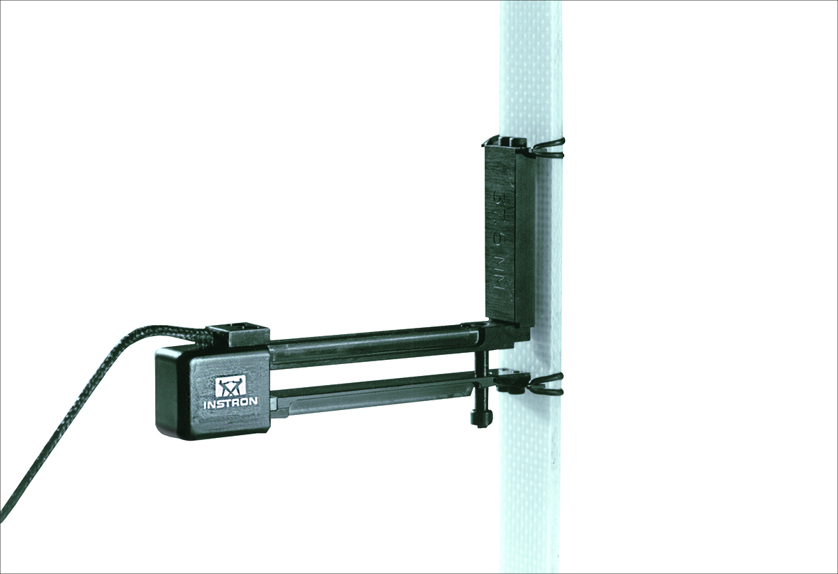
The 2620 Series dynamic strain gauge extensometers are accurate lightweight units used for direct measurement and closed-loop control of strain in a variety of static and high frequency cyclic materials testing applications. Tensile, compressive, low and high cycle fatigue testing, creep and stress relaxation as well as straight line (ramp) testing may be performed with the 2620 series dynamic strain gauge extensometer to an extensive range of national and international standards.

Principle Of Operation

The 2620 Series extensometers are strain gauge units. The flexural element is a special alloy operating beam with fatigue certified foil gauges bonded to it. The gauges are arranged in a fully active four-arm Wheatstone bridge circuit. It is mounted in a lightweight frame and accurately follows the strain amplitudes applied to it. Variations of gauge length and percentage strain levels may be achieved by the addition of gauge length extenders. Integrated mechanical stops limit the amount of overtravel in the extensometers, enabling them to survive specimen rupture without damage.

Application Range

The 2620 Series extensometers are designed for use with metals, composites, plastics, wood and other materials exhibiting total strains up to ±50% of the original gauge length. They are immersible in a range of fluids (acetone, mineral and silicone oils, alcohol and similar cooling/heating fluids) and can be quickly and easily calibrated.

Accessories

Item Name Gauge Length % Travel (Axial) Cat#
Dynamic Extensometer 12.5mm GL ±5mm Travel 12.5, 25, and 50 mm ±40, ±20, and ±10% 2620-601
Dynamic Extensometer 12.5mm GL ±2.5mm Travel 12.5, 25, and 50 mm ±20, ±10, and ±5% 2620-602
Dynamic Extensometer 10mm GL ±1mm Travel 10, 25, and 50 mm ±10, ±4, and ±2% 2620-603
Dynamic Extensometer 25mm GL +12.5mm -2.5mm Travel 25 and 50 mm +50 to -10% and +25 to -5% 2620-604

Webbing Capstan Tensile Grips

WEBBING CAPSTAN TENSILE GRIPS

For Testing High-Strength Textile Materials

Webbing Capstan Tensile Grips

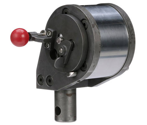
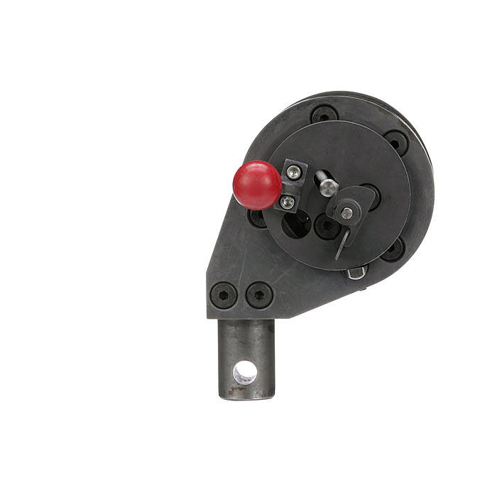
Webbing capstan grips are designed to permit faster, easier testing of seat belts and other high strength belts and tapes. Based on the capstan principle, these grips minimize slippage and jaw breakage effects, and permit the predetermination of specimen length while allowing for quick, convenient loading.

Principle of Operation

These webbing capstan grips incorporate an ingenious double capstan design which provides fast, easy loading with a gripping action that results in proper breaks in the full gauge length of the specimen. The key to the ease of loading is the use of an inner and outer capstan. The specimen is loaded simply by inserting one end into the groove of the inner capstan and cranking it through 360 degrees. Gripping efficiency is also greatly increased because the surfaces of both capstans are utilized.

Application Range

  • Type of loading: static tensile
  • Specimen materials: webbing, belts, tapes
  • Specimen shapes: flat

2715-003-01-08
Specifications
Catalog no. 2715-003
Capacity 50 kN
Standards ASTM D6775, D3950
Maximum Specimen Width 50.8 mm
Maximum Specimen Thickness 4.75 mm
Temperature Range -29 °C to 121 °C
Upper and Lower Fittings Type Dm (1.25 in connection with 1/2 in clevis pin).
Rigid coupling required.
Brochure Download

Translation and Clamping Stages

Translation and Clamping Stages

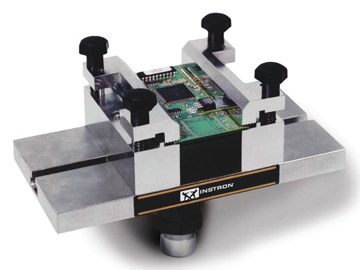
Translation and clamping stages are used to precisely position and align a test specimen beneath the actuator, ensuring accurate setup before testing begins. These stages provide secure, adjustable positioning for microelectronic circuit boards and small components, helping maintain proper alignment and stability within the testing system for reliable and repeatable results.

PCB Clamping Stage

Catalog No. 2860-200

The clamping stage may be mounted directly to the base of a testing machine in order to provide accurate adjustment and indexing of the specimen position during testing. In a typical test configuration the assembly under test would be mounted in the PCB clamping stage fitted to an X-Y translation stage or directly to the base of a test machine and a lead pull grip would be mounted below the load cell on the moving crosshead or actuator.

Overview
Capacity 500 N
Clamping Span Adjustable: 0 to 150 mm

Theta-X-Y Manual Translation Stage

Catalog No. 2860-101

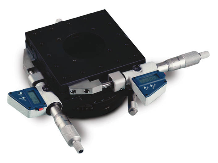
The Theta-X-Y manual translation stage provides the facility to precisely position and align a test specimen below the actuator (two axes). Theta (angle) and X-Y axes are also adjustable via digital micrometers. The rotary axis can be adjusted via a micrometer and has a vernier scale readable to 5 ft. The X-Y axes micrometers have a resolution of 1 micron. The axes are arranged with the angle stage at the base, with the X-Y stage on top. This allows the test platform to be oriented with the X-Y axes referenced to the specimen. Typical applications include lead pull and component pull off tests on microelectronic devices and PCB’s.

Overview
Capacity 1 kN
Travel (X and Y) ±12.5 mm
Temperature Ambient only

Pneumatic Cord and Yarn Tensile Grips

PNEUMATIC CORD AND YARN TENSILE GRIPS

For Testing Fiber, Cord, Yarns, and Fine Braided Wires

Textile Cord, Yarn, and Rope Tensile_Grips

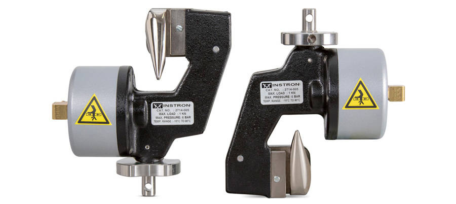
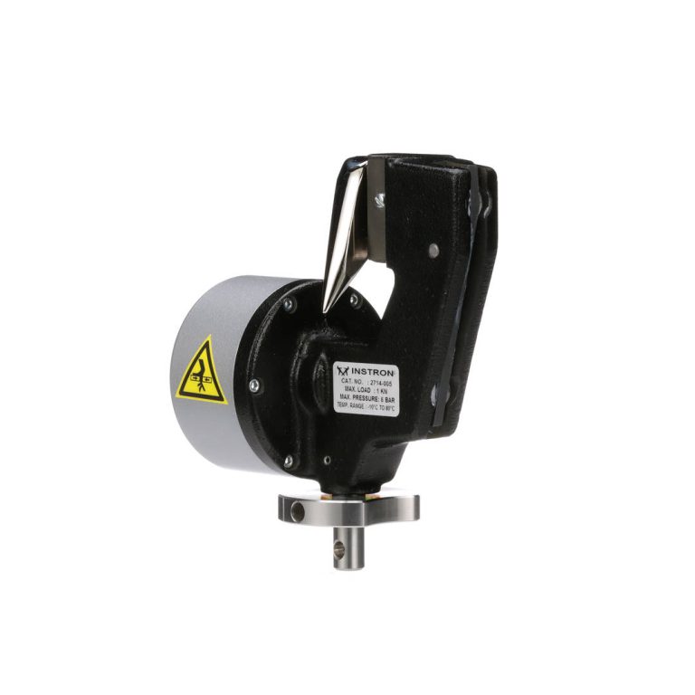
Pneumatic cord and yarn grips provide a convenient method for clamping fiber, cord, yarns and fine braided wires to reduce the problem of jaw breaks associated with testing these materials. A specially designed horn with a smooth finish and a contoured surface with a graduated cam allows for easy loading and a stress reduced clamping area on the specimen. The clamping mechanism can be activated either automatically or through a foot switch. This allows hands-free grip operation enabling the specimen to be held with both hands for easy loading. Pneumatic cord and yarn grips provide a selectable clamping force to accommodate different materials and excellent follow-up action which compensates for decay of the holding force due to specimen creep.

Principle of Operation

Where the gripping area of mono-filaments, cord and yarn is small in relation to the strength, normal techniques using standard grip faces usually result in specimen failures adjacent to the jaw faces. The pneumatic cord and yarn grips have been designed specifically to overcome the problem of specimen failure by incorporating a capstan design which evenly distributes the gripping force over the surface of a curved half capstan through friction.

In addition, the pneumatically cushioned gripping force applied to the ends of the specimen compensates for the decay of force due to specimen creep.The pneumatics activate a moveable face, which acts upon a contoured fixed gripping face. This serves as a capstan and provides support for the specimen, making the transition from the free stressed length of specimen to the rigidly clamped portion gradually rather than abruptly, thus minimizing breakage of the specimen adjacent to the jaw face. The capstan also incorporates a polished guide horn, which assists in rapid specimen loading. The polished finish prevents damage to individual fibres during specimen insertion.

The specimen is placed over the top of the horn and slides down to the proper gripping position on the contoured clamp. The grips may be closed or opened by a pneumatic footswitch for hands free operation. An automatic air kit is also available for hands free, automated, and pretension testing via software or system default settings.

Application Range

  • Type of loading: tensile, static and tension cyclic tests
  • Not suitable for high cycle fatigue tests
  • Specimen materials: fine braided wires, cords, yarns, mono-filaments
  • Specimen shapes: round

Available Models

Force Capacity Maximum Specimen Diameter Catalog no. View Full Specifications
50 N 2.4 mm 2714-031 Download Brochure
1 kN 3.2 mm 2714-005 Download Brochure
1 kN [High Temperature] 3.2 mm 2734-007 Click Here
2 kN 4.8 mm 2714-040 Download Brochure