Temperature Calibration
Instron’s Temperature Calibration service ensures that testing parameters are being met and that associated results are being calculated accurately.
- Services
- 02/08/2024
- 729.2 KB
Instron’s Temperature Calibration service ensures that testing parameters are being met and that associated results are being calculated accurately.
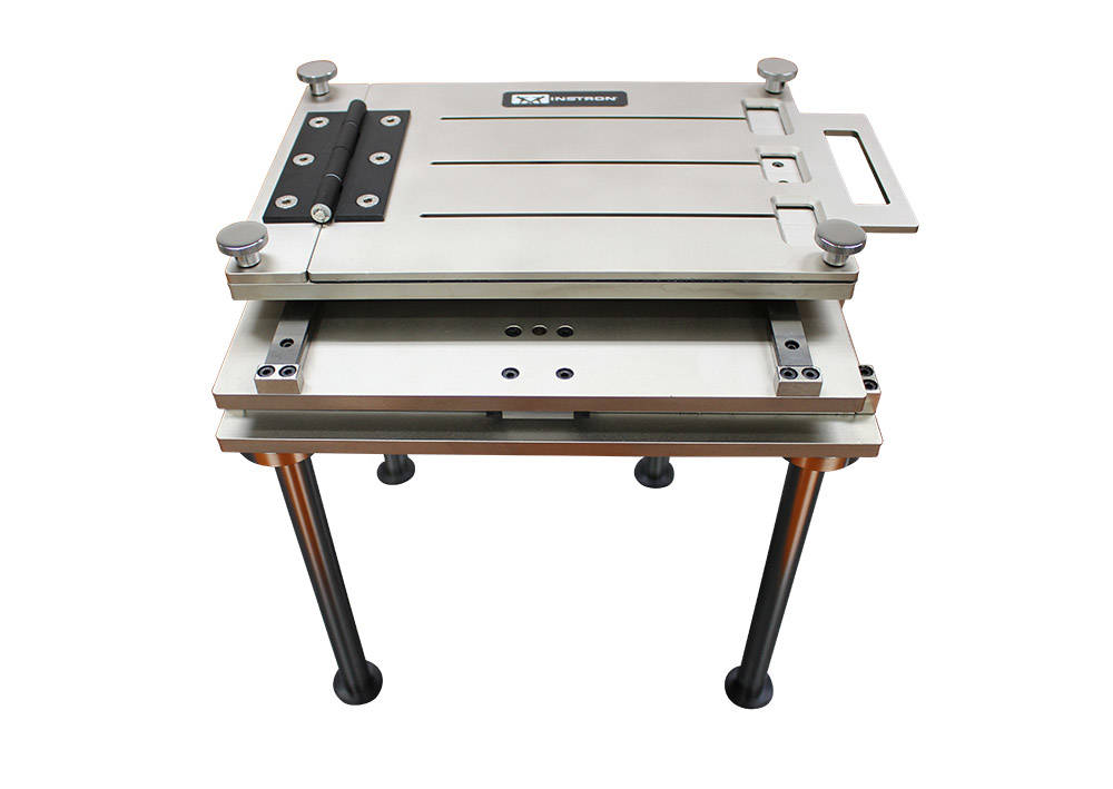
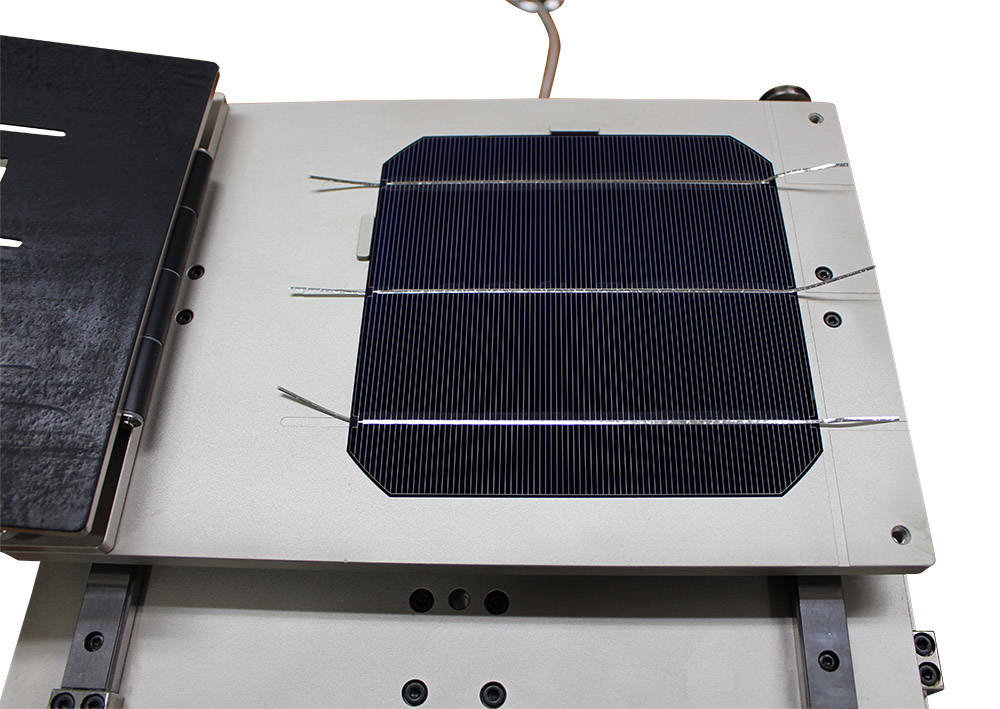
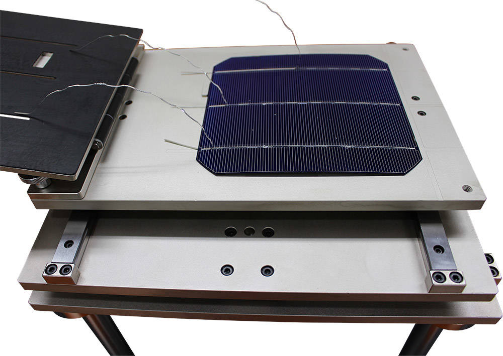
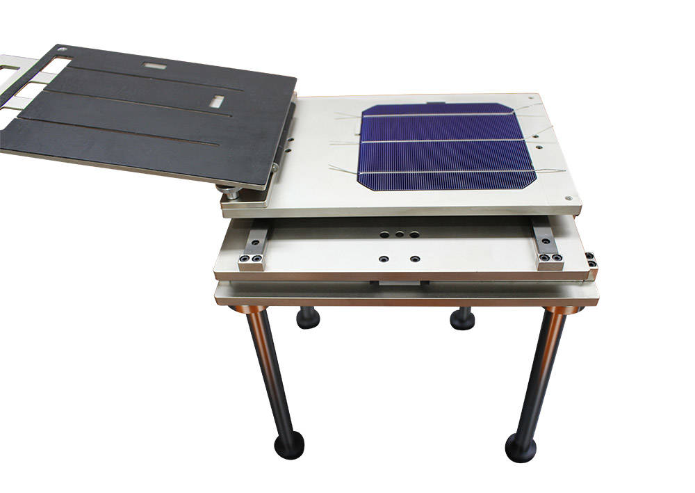
Avec un intérêt mondial croissant pour l’énergie verte, les entreprises s’efforcent de développer des cellules solaires plus efficaces et moins coûteuses pour une variété d’applications. Les fabricants reconnaissent la nécessité d’essais mécaniques pour évaluer les performances des films minces et des substrats utilisés pour fabriquer les cellules photovoltaïques (PV), également appelées cellules solaires.
La Commission électrotechnique internationale (CEI), une organisation internationale de normalisation de premier plan, publie la série IEC 61215, Modules photovoltaïques terrestres (PV) – Qualification de la conception et homologation, qui s’applique aux modules en silicium cristallin et à couches minces. La série comprend des essais mécaniques de modules PV qui simulent des conditions externes, telles que la résistance à des charges de vent équivalentes à 130 km/h.
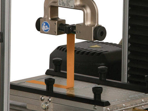
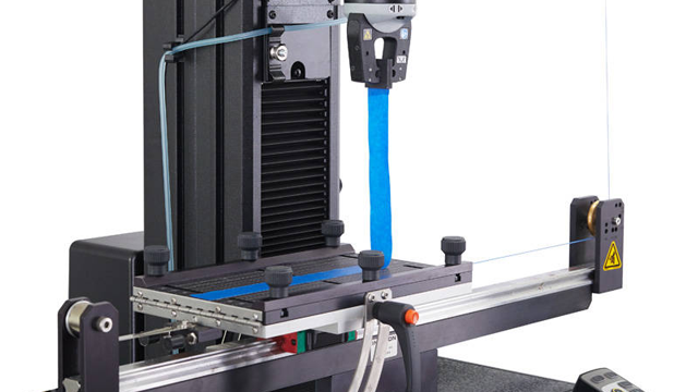
Un essai d’adhérence par pelage à 90 degrés sur les différentes couches de film mince, également appelées empilements, est recommandé pour relever ces défis. L’essai confirme la qualité de l’adhérence entre les couches, et la résistance au pelage résultante fournit une estimation de l’adhérence nécessaire pour une interconnexion électrique fiable et à long terme entre les couches.
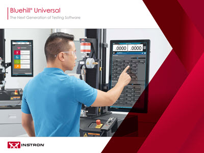
Les systèmes d’essai universels série 6800 et série 3400 d’Instron sont bien adaptés aux applications d’essai de pelage à 90 degrés. Le logiciel Bluehill® Universal peut être utilisé pour configurer les méthodes d’essai et analyser les résultats après l’essai.
La fixation de pelage à 90 degrés est conçue pour minimiser le frottement, de sorte que les mesures de force reflètent le film et l’adhésif testés. Instron propose également une fixation de pelage à angle variable pour tester les modules PV à des angles autres que 90 degrés, tels que les essais de pelage à 45 ou 30 degrés.
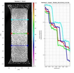
The results will vary depending on the location of the extensometer on the specimen. Shown in the image is a specimen with 4 different transverse gauge lengths using Digital Image Correlation Software. The effects of the extensometer attachment gives different transverse strain values. This would cause a difference in the r-value calculation. Manual placement of the extensometer will influence the transverse strain measurement.

Sheet metal product development is currently driven by the demand for increasing strength with minimal impact to the formability. Where there has traditionally been a trade-off between strength and formability, sheet metal producers are now offering ever higher grades where the reduction in formability is minimal despite considerable strength gains. The automotive industry is the greatest driver for increasing strength, meaning thinner/lighter material can be used in the production of cars, reducing the overall emissions per mile/kilometer. The plastic strain ratio (r-value) and the strain hardening exponent (n-value) are critical mechanical properties that define the formability of these materials.
What is r-value? - Plastic Strain Ratio
What is n-value? - Strain Hardening Exponent
During a tensile test, these formability properties can be calculated automatically in real time using Bluehill® Universal materials testing software.
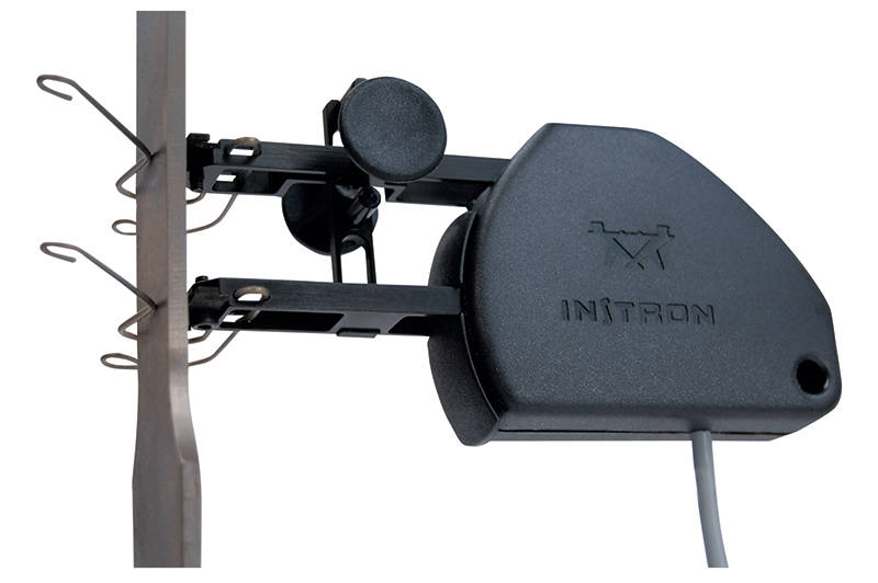
To determine n-value, axial strain needs to be measured after yield. The accuracy of the device needs to, at least, be suitable for higher elongations as primary metals tensile standards will have lower accuracy requirements for calculations determined at higher strains. Some traditional contacting extensometers are designed to be removed during the test and may be limited on total travel. The latest technology, such as the AVE3 Advanced Video Extensometer or the AutoX Biaxial automatic contacting extensometer, can measure strain throughout the test and ensure the highest accuracy of results.
A sheet metal manufacturer often applies a plastic strain ratio (r-value) threshold as a key product acceptance criterion. If the r-value is low, the sheet metal is rejected, therefore the accuracy of the strain measurement data is critical. For determining r-value, transverse strain needs to be measured in conjunction with the axial strain. Traditionally, this required using two compatible clip-on extensometers where the operator must ensure firm attachment and proper location.
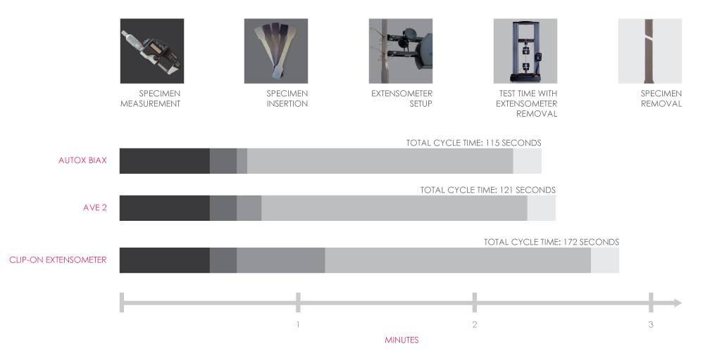
Using an automatic extensometer for axial strain can improve throughput; utilizing them for both axial and transverse strain has an even greater improvement. Automatic contacting extensometers can be more than 30% faster per test compared to two clip-on extensometers. The repeatability will also improve as the extensometer is always attached to the specimen in the same location. In addition, the AverEdge32™ feature of the AVE 2 has shown substantial improvement in reducing transverse strain measurement variability by providing a real-time average of multiple transverse strain measurements.
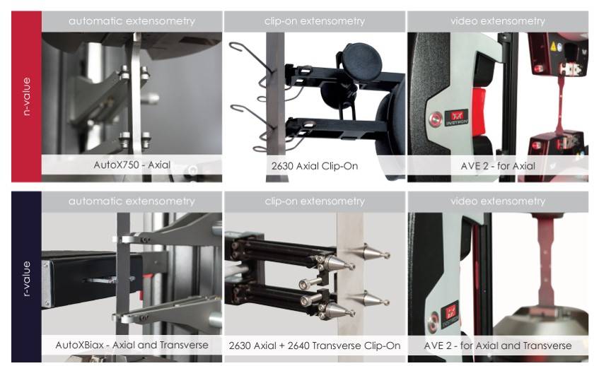
Extensometer choices for r and n testing:
The graph below shows the beneficial effect of using advanced strain solutions. The fixed times between the various extensometers are the specimen measurement, specimen insertion & removal, and test time. Extensometer setup time is variable, and clip-on extensometers need to be removed during a test for high-strength steels with violent fractures.
Challenge: Repeatable Results
The global demand for medical equipment has skyrocketed in response to the COVID-19 pandemic, with many companies refocusing their efforts to produce personal protective equipment (PPE). With this vast uptick in demand, medical device manufacturers have scrambled to increase their production capacities while non-medical manufacturing companies have transitioned their own production facilities to create items such as masks, gloves, and nasal swabs.
With increased manufacturing comes increased quality control testing, and Instron has received numerous inquiries from companies seeking to expand their testing capacity or reconfigure their existing equipment to test PPE. This guide was created to help familiarize manufacturers with key testing requirements and provide an overview of current FDA regulations. We hope that it will be a useful resource for anyone seeking to aid the fight against COVID-19.
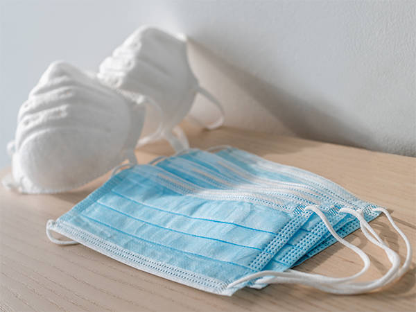
Medical masks come in two primary types: single-use surgical masks and N95 respirator masks. Surgical masks are intended to prevent viral spread by containing droplets produced by the wearer, while respirator masks are designed to protect the wearer from virus particles that have been aerosolized. Both of these masks are relatively easy to manufacture and test, and many textile manufacturers have shifted their operations to produce them in an attempt to meet the current demand. Many of these companies already own materials testing equipment and are able to make small modifications to their existing systems in order to perform the required FDA testing.
Fabric Test
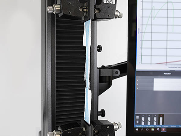
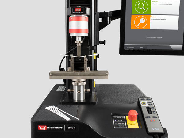
Mask fabric is generally tested in accordance with general textile standards such as ASTM D5034. Because fabric samples are prone to jaw breaks, we recommend pneumatic grips with smooth jaw faces to minimize this risk. In order to capture peaks and troughs generated by individual fiber breaks, we recommend a test system with a high data capture rate, such as Instron's 68SC-5.
Elastic Test
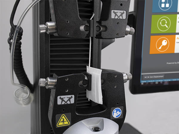
It is important to test the strength of the connection between a mask's fabric and the elastic band that holds it into place. This test is performed by loading the band to a minimum of 10 N and visually evaluating it to ensure there has been no separation. With masks now being worn for longer periods of time than ever, it may also be valuable to perform a relaxation test to determine its durability.
Filter Test
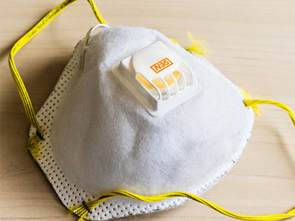
Respirator masks must be tested to ensure the strength of connection between the mask fabric and the respirator valve. This test can be accomplished using a side-acting grip on the base of the system and a custom-made hook fixture attached to the load cell.
ASTM classifies medical gloves according to their material (latex, nitrile, natural rubber, PVC, or polychloroprene), while ISO classifies them based on their application (patient examination or surgical). Regardless of the testing standard, material, or clinical application, the equipment and general procedure for testing is consistent across all medical glove types. ASTM D6319, ISO 11193, and EN 455-2 are standards used by the biomedical industry to regulate the tensile properties of medical gloves. The key results for all glove testing standards are the tensile strength and ultimate elongation of the material. Rather than testing the entire glove, a dogbone specimen is cut from the finished glove and testing in accordance to the relevant elastomeric standard (ASTM D412 or ISO 37).
| Glove Test Setup | |
|---|---|
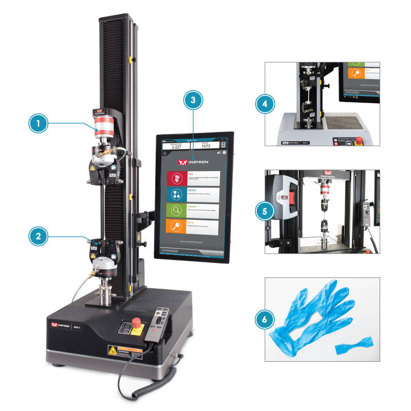
| 1) | Load Cell A 500N load cell is an appropriate capacity for all glove materials. |
| 2) | Pneumatic Grips Air pressurized grips ensure consistent clamping forces Jaw faces are easily interchangeable to ensure the correct surface texture is used for the material. Elastomeric materials like rubber gloves typically require rubber coated faces due to how thin the specimen is. The rubber coating is able to prevent slippage of the material without damaging the specimen. |
| 3) | Bluehill Software The biomedical method suite includes preconfigured methods for EN455-2 |
| 4) | Elastomeric Roller Grips Roller grips provide a cost effective gripping solution for thin elastomers The roller grip utilizes a proportional clamping pressure which increases as more force is applied to the specimen |
| 5) | AVE 2.0 An optical non-contacting strain device can be used to ensure more accurate strain measurement |
| 6) | Specimen Preparation All the major ASTM/ISO/EN standards require a dumbbell shaped specimen to be stamped from the palm of the glove EN 455-2 takes into consideration the potential discrepancies in thickness between the palm and the fingertips. The standard compares their thickness and uses a correction factor for the tensile strength of the speicmen. |
Nasopharyngeal (NP) swabs are crucial tools in the diagnosis of influenza and respiratory diseases. Despite their similar appearance, these swabs are considerably more specialized than the standard cotton swabs used for personal hygiene, using synthetic fibers for the swab staff and tiny bristles for the swab tip. In an effort to bolster the global supply, significant collaborations have occurred between 3D printer manufacturers and medical research teams, which have resulted in a massive increase in production capacity of test quality NP swabs. It is critical to perform mechanical testing to determine if the performance of the 3D printed swabs is comparable to the performance of those produced by standard methods.
3 Point Bend Test
Nasal Swabs are subjected to flexural forces as they travel through the nasal passage. 3 point bend tests help characterize these stresses. It is also important to evaluate the weak point at the tip of the swab which helps achieve the correct size for transport. Instron's standard 2810-400 3-point bend fixture with 10 mm diameter anvils is ideal for these applications.
Cantilever Bend
The cantilever bend test best represents the stresses seen when the swab is held during the procedure. The material needs to be flexible enough to ensure it will not fail during the test. This setup is accomplished using a component test plate and an advanced screw action grip to hold the specimen in place. Any probe can be used to deflect the tip of the swab.
Tip Shear Strength
The tip of an NP swab is made of tiny bristles that allow for maximum sample collection. These bristles need to withstand shear forces as they move across the walls of the nasal passage. In order to test this property, the tip and base of the swab are clamped with advanced screw action grips to evaluate the maximum force required to break the bristles or the tip itself.
FDA Requirements in the Age of COVID-19
The Food and Drug Administration is the main regulatory body overseeing the production and distribution of PPE in the United States. The level of FDA involvement depends on the class of the device, which can range from class 1 to class 3 based on the device’s potential risk of nonconformance. Most types of PPE are labeled as class 1 devices, which have the fewest barriers to approval.
Because it can take months or even years to gain FDA approval, in times of health crisis the FDA issues something called an Emergency Use Authorization (EUA). An EUA essentially loosens the requirements for production and distribution of certain medical products to allow production to ramp up quickly. EUAs are currently being granted to manufacturers of COVID test kits, virus therapies, ventilators, respirators, and PPE. These emergency authorizations are generally granted to specific companies who apply to expedite the approval process, but they are also being released as blanket statements covering certain types of PPE so that smaller companies can also participate with minimal red tape. The EUAs include additional documentation that outline the enforcement policy for PPE manufacturing during the current public health emergency and provides criteria for quality control standards as well as the required labeling of products released under the authorization.
Utilisez les liens ci-dessous pour accéder directement à la section qui vous intéresse :
Pourquoi le contrôle de déformation ? | Exigences pour obtenir un contrôle de déformation en boucle fermée | Avantages du contrôle de déformation en boucle fermée
Certaines propriétés mécaniques des métaux sont affectées par la vitesse de l’essai et sont donc « sensibles à la vitesse de déformation ». En 2009, l’une des principales normes d’essai des métaux, ASTM E8, a été mise à jour pour inclure une méthode basée sur le contrôle de la vitesse de déformation sur l’éprouvette. Avant cette modification, les essais ne pouvaient être effectués qu’en contrôle de contrainte ou en contrôle de vitesse de traverse, où la rigidité globale de la machine peut affecter la vitesse sur l’éprouvette et entraîner des différences dans les résultats. Lors de l’essai de matériaux sensibles à la déformation avec un contrôle de vitesse de traverse, les vitesses d’essai autorisées peuvent provoquer une différence de plus de 10 % dans les résultats de limite d’élasticité entre les essais effectués à la vitesse la plus lente et la plus rapide autorisée dans ASTM E8/E8M et ISO 6892-1.
Effectuer un essai en contrôle de déformation permet toutefois à la vitesse d’essai de varier pendant l’essai afin de compenser la compliance de la machine et de maintenir une vitesse de déformation constante sur l’éprouvette. Cette méthode augmente la productivité en réduisant le temps d’essai global. Elle peut également faire gagner du temps et éviter de gaspiller des éprouvettes lors du réglage. Contrairement à la méthode de contrôle de contrainte, le contrôle de déformation en boucle fermée ne nécessite pas de multiples ajustements par essais et erreurs de la vitesse de traverse pour garantir que la vitesse de déformation est conforme aux normes d’essai.
Pour qu'un système d'essai atteigne le contrôle de déformation en boucle fermée, certaines exigences doivent être satisfaites. Dans tous les cas, il est important que la machine d'essai et l'extensomètre soient isolés de toute vibration ou choc soudain ou répétitif, car cela pourrait causer des interférences dans vos essais.
Un extensomètre est un dispositif de haute précision utilisé pour mesurer la déformation d'une éprouvette. Les extensomètres éliminent la compliance du système du calcul de la mesure de déformation, mais il est important que l'extensomètre choisi soit approprié pour la longueur de déplacement de l'éprouvette et ait un rapport approprié entre la longueur parallèle et la longueur de référence.
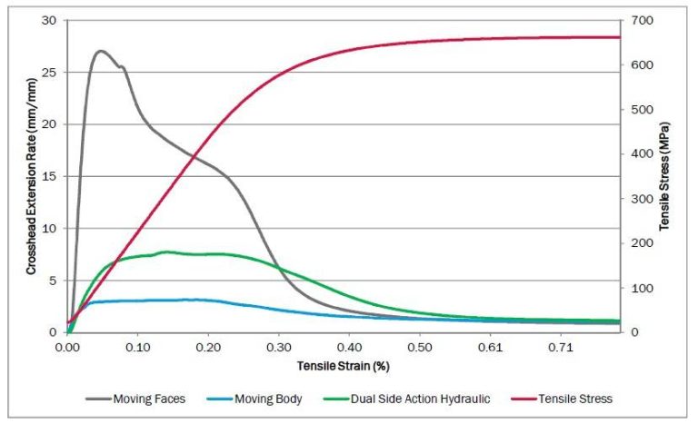
Les mors doivent maintenir fermement l'éprouvette pendant l'essai, de préférence avec une rigidité élevée et une compliance minimale. Le graphique montre comment différents types de dispositifs de serrage peuvent affecter la rigidité du système et comment une machine en contrôle de déformation devrait compenser.
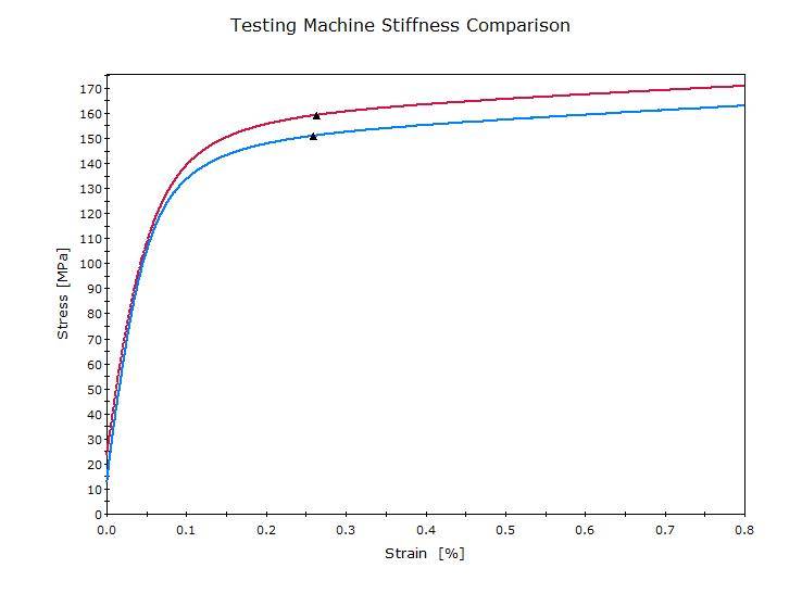
Le bâti de charge du système d'essai nécessite un système d'entraînement précis et stable avec une rigidité élevée. À droite se trouve une courbe contrainte-déformation sur des matériaux nominalement similaires — l'un testé sur un bâti à rigidité élevée et l'autre sur un bâti à faible rigidité. En utilisant un calcul de méthode de déformation estimée, les deux essais sont effectués à une vitesse de traverse constante de 2,25 mm/min. Il y avait une différence de 21 % dans la « vitesse de l'éprouvette » (exprimée en mm/min), ce qui a conduit à une différence de 5 % dans le résultat de limite d'élasticité.
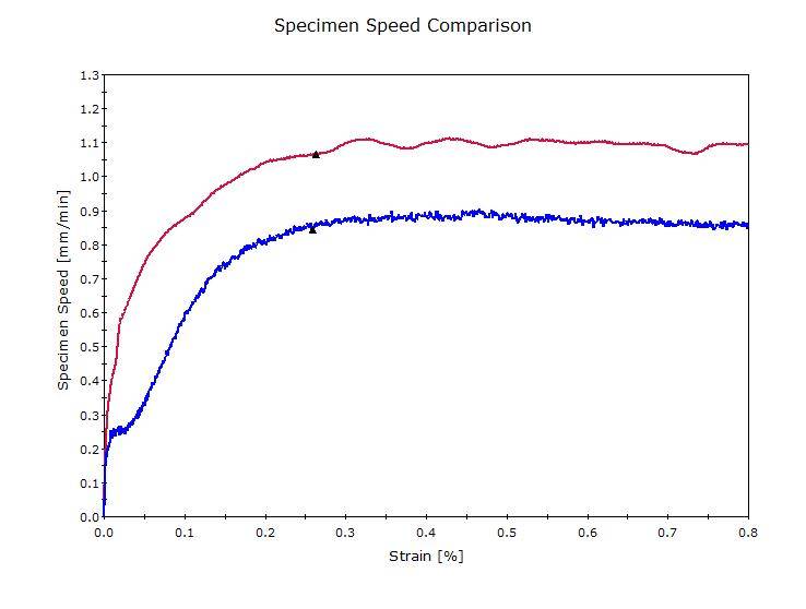
Ce graphique montre la différence de vitesse de l'éprouvette entre un système « rigide » et un système moins rigide. Au début de l'essai, il est montré que le mouvement de la traverse est transféré en déformation sur l'éprouvette très rapidement, alors que sur le système plus faible, cela prend plus de temps. Cela est dû à la déflexion de la machine/cellule de charge/mors, qui fait que ce mouvement n'est pas transféré à l'éprouvette. Si les deux machines utilisaient le contrôle de déformation, les résultats seraient beaucoup plus comparables, mais le contrôle sera probablement plus difficile sur le système plus faible.
Les machines capables de contrôle de vitesse de déformation nécessitent un contrôleur réactif et un système d'entraînement précis et stable afin de maintenir les tolérances requises par la norme d'essai. Certaines machines sont annoncées comme étant capables d'atteindre cette méthode mais nécessitent que l'utilisateur règle manuellement les paramètres de gain du contrôleur, ce qui peut être difficile même pour l'opérateur de système le plus expérimenté.
Une éprouvette proportionnelle et un extensomètre à longueur de référence proportionnelle sont idéaux. En réalité, une éprouvette avec un bon rapport longueur de référence/longueur parallèle est bien adaptée pour minimiser la déformation observée en dehors de la longueur de référence, permettant au contrôle d'être plus stable. Si vos éprouvettes varient d'un écoulement discontinu à un écoulement continu, il est important de changer de méthode de contrôle pour chaque type. Comme un écoulement local peut se produire en dehors de la longueur de référence sur un matériau à écoulement discontinu, il est impossible de contrôler à partir du retour de déformation et devrait être en contrôle de vitesse de traverse pendant l'allongement au point d'écoulement [YPE/Ae].
✓ Résultats plus reproductibles et comparables - les résultats d'essai sont fiables d'une machine à l'autre
✓ Efficacité améliorée - le temps par essai est minimisé et le temps de configuration réduit
✓ Pas besoin de régler avec une éprouvette lors de l'utilisation d'un système d'essai avec électronique de contrôleur série 6800
The Challenge
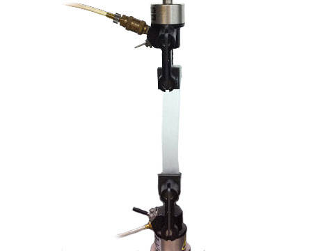
A critical part of Li-ion or other liquid electrolyte batteries, separators are films most commonly made of polymers and must be mechanically strong enough to withstand the winding operation during the battery’s assembly. The critical mechanical properties suppliers must control are tensile strength, elongation, and puncture resistance.
Our Solution
ASTM D882 outlines the tensile testing of thin plastic film, which is suitable for polymer separators. Instron offers a variety of testing solutions that comply with D882. The different tiers of product offerings provide superior accuracy and throughput for labs that require it and more affordable solutions for labs that do not. Please review Instron’s ASTM D882 Definitive Guide for additional details. Relating to puncture tests, ASTM F1306 outlines the puncture testing of flexible barrier films to characterize the material response when a 3.2 mm diameter probe is driven into a clamped specimen. Instron’s S1-14110 fixture is in compliance with the recommended fixture specifications described in F1306.
THE CHALLENGE
Some vehicle textiles have multiple layers or backings, and must be subjected to a peel test in order to determine if adhesion forces are appropriate.
Our Solution
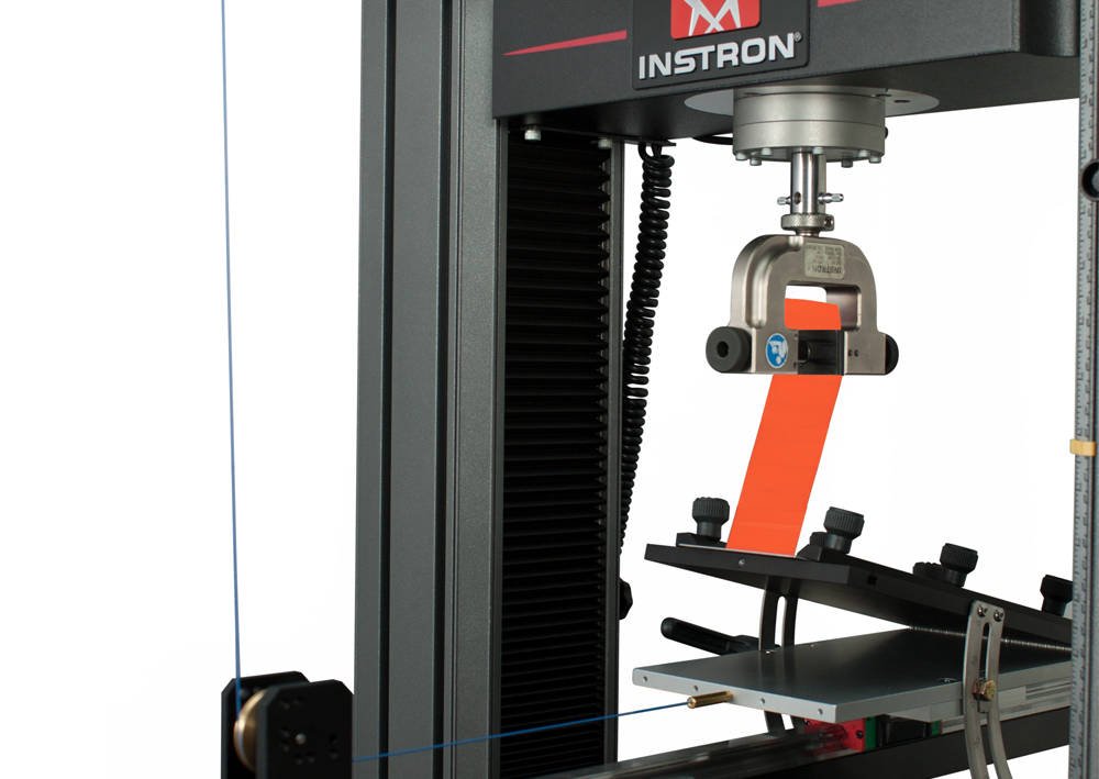
Instron® pneumatic side action grips are able to grip delicate foam specimens in order to perform T-peel tests. With a variety of quick-release jaw faces, these grips allow users to easily test a range of materials with a single system. The air pressure is also adjustable, allowing operators to fine tune the gripping pressure if needed.
Bluehill® Universal software contains a suite of calculations for peel testing, including industry standard calculations, such as first peak, average peel force over a given length, and even allows for custom calculations.
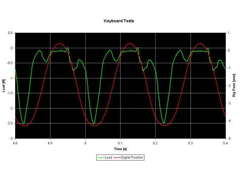
Increasing miniaturization of mobile phones means that the alpha numeric keypads used for number dialing and data entry are also becoming smaller. These keypads must be tested to ensure that they are easy enough to use. One measure of this performance is the activation force and profile of individual keys on the keypad. The force required to activate the key should be sufficiently low that the key is easy to press, considering that the phone may be operated by, for example, the elderly. However, the force should not be so low that accidental key presses are likely, for example when the phone is carried in a pocket or handbag.
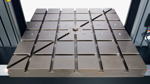
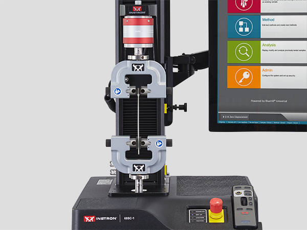
A basic system for keypad testing comprises of a universal testing machine, equipped with a low capacity load cell, and a chuck fixture holding a steel prong. Additionally, a platen or t-slot table is used to support the phone or keypad module. During the test, the load profile, and sometimes the displacement characteristic of the key press, are monitored.
For more detailed information, the electrical contact can be wired into the test system, providing precise determination of the switch closure position and force. In order to provide accurate data, a system with a high data logging rate should be used, so that rapid changes in force which occur over very small distances at switch closure can be observed. In addition, the system used should have high position accuracy and control to avoid damage to delicate components.

Instron 6800 Series Universal Testing Systems provide unparalleled accuracy and reliability. Built on a patent-pending Operator Protect system architecture with an all-new Smart-Close Air Kit and Collision Mitigation features, the 6800 Series makes materials testing simpler, smarter, and safer than ever before.
Instron 3400 Series universal testing systems for tensile, compression, bend, and other material property tests.
Bluehill Universal is Instron’s advanced materials testing software, designed for intuitive touch interaction and streamlined workflows. It offers pre-loaded test methods, QuickTest for rapid setup, enhanced data exporting, and Instron Connect for direct service communication. Users of Bluehill 2 and Bluehill 3 can easily upgrade to the latest version for improved performance and usability.