Display Panel Testing

Display Panel Testing

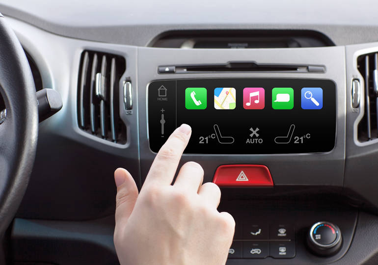
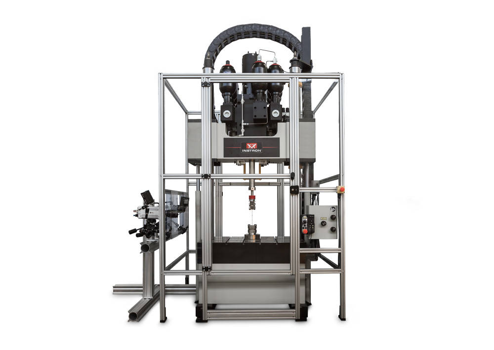
As infotainment display panels and screens are becoming standard features in many automobiles, it is important for manufacturers to understand their mechanical reliability. These displays need to last the lifetime of the vehicle, much longer than a standard electronic device. Therefore, it is relevant to study their mechanical reliability.

The Challengeautomotive


Display panels need to withstand years of abuse.  A multitude of rigorous testing needs to be completed to ensure the panel will last.  Compression testing should be completed on multiple locations on the panel which has historically been very time-consuming.  Additionally, flexure tests are also conducted, sometimes to a point of failure.  Panels can fail out of nowhere and it can be hard to observe the break.  All these factors make display testing challenging.

Our Solution


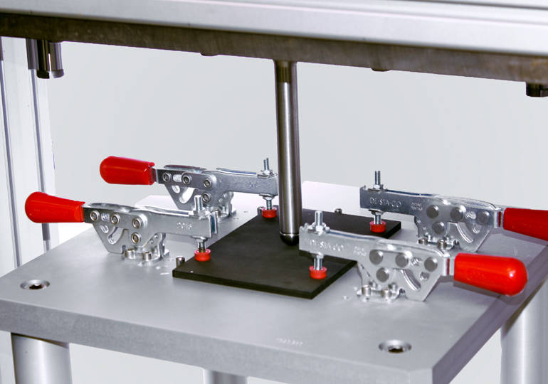
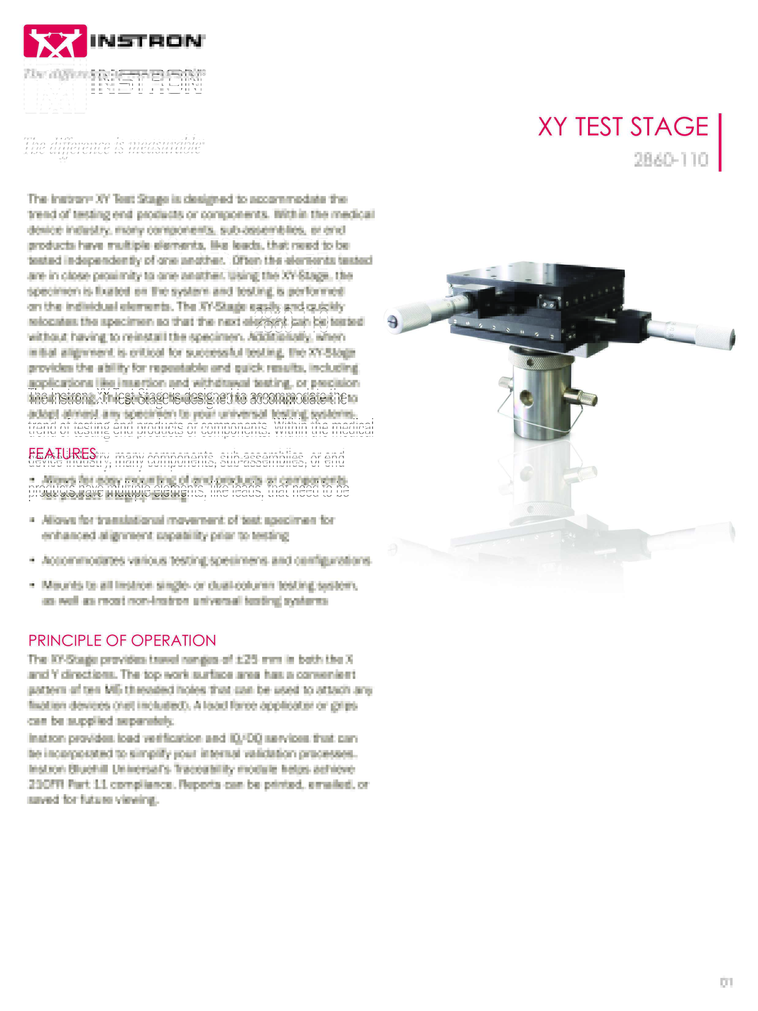
Instron® offers an Automated XY Stage that will move the display panel so that compression testing can be completed at multiple locations.  The stage is driven to different points taught by the operator using the Multi-Test module for Bluehill® Universal software. The test is then automated so all points can be tested in a single run at high speed. Probes of different sizes are available as well.

With a variety of flex/bend fixtures, Instron is able to meet most any display panel bend test need. Fixtures include both 3 and 4 point models with fixed and variable span options. Fixtures also can be altered with a variety of options. If you have a unique bend test need, Instron's Custom Solutions Group can work with you to develop a fixture to your specifications.

Understand failure visually and how it correlates to test data with the TestCam module for test recording and playback. Capture high-speed videos in real time and play them back to get a complete understanding of how the panel reacts at break.

Essai de Compressibilité après Impact des COMPOSITES

Essai de Compressibilité après Impact des COMPOSITES

L’essai de compression après impact (CAI) est utilisé pour définir la résistance à l’endommagement des composites après un impact. Un impact sur un panneau stratifié en composite peut ne provoquer aucun dommage externe visible, mais il peut entraîner une réduction spectaculaire de la résistance en compression. La conception de pièces automobiles utilisant des matériaux composites doit tenir compte des effets des impacts sur les propriétés du matériau. Ces données peuvent être obtenues conformément à des normes dédiées (telles que ASTM D7136M, ASTM D7136), à l’aide d’une tour de chute Instron configurée avec des accessoires CAI.

LE DÉFI

composites

Tout en présentant dexcellentes propriétés mécaniques (cest-à-dire résistance et rigidité) pour un poids inférieur, par rapport à leurs équivalents métalliques, les composites peuvent présenter une faible tolérance aux dommages causés par impact. Les types de dommages peuvent être complexes, de forme irrégulière, et peuvent affecter toutes les couches de la structure. De plus, ils peuvent être à peine visibles ou dissimulés à la vue.

Les impacts à faible énergie peuvent être considérés comme les plus dangereux, car les dommages quils provoquent peuvent passer inaperçus lors des inspections visuelles de routine de la surface impactée. Les énergies dimpact qui causent des dommages visibles au composant peuvent être nettement plus élevées que celles qui ont un effet significatif sur les propriétés mécaniques.

Létude de la tolérance aux dommages des stratifiés et de leffet de différentes énergies dimpact sur la résistance résiduelle est cruciale.

Notre solution

Tour de chute dimpact Instron 9450

Avec la tour de chute d’impact Instron® 9450, la tolérance aux dommages des stratifiés peut être étudiée et l’effet de différentes énergies d’impact sur la résistance résiduelle peut être déterminé. La réalisation d’un essai CAI sur des composants montre que les matériaux réagissent différemment selon les conditions d’impact, et permet aux ingénieurs de concevoir et de tester des produits composites de manière plus rentable.

Lorsqu’elle est configurée avec un percuteur instrumenté, un système d’acquisition de données et un logiciel, le signal de force de chaque impact peut être capturé et analysé, aidant les ingénieurs à approfondir leurs connaissances sur les performances du matériau. L’ajout d’une chambre de température spéciale permet à l’utilisateur d’étudier la réaction d’un même matériau dans des environnements à haute température jusqu’à 300°C.

Contactez-nous pour en savoir plus sur nos solutions automobiles.

Essai de flexion de PCB selon AEC-Q200-005

Essai de flexion de PCB selon AEC-Q200-005

La norme AEC-Q200-005 Rev A définit la norme de vérification de la résistance de liaison des composants montés en surface sur les cartes de circuits imprimés (PCB) finies, en testant leur capacité à résister aux forces de flexion, de pliage et de traction. Les fabricants d'assemblages électroniques qui fournissent les équipementiers automobiles utilisent cet essai pour caractériser la résistance de liaison des adhésifs et des joints de soudure qui maintiennent les composants montés en surface et leurs connexions en place sur un PCB.

Configuration d'essai

La norme exige que le PCB fini soit positionné à l'envers sur deux enclumes inférieures, la force étant appliquée à l'emplacement cible par une enclume supérieure. La carte est fléchie d'au moins 2 mm et maintenue à cette déflexion pendant 60 (+5) secondes. Une fois l'essai terminé, les composants fléchis doivent être minutieusement inspectés visuellement.
Solutions d'essai recommandées

Un système d'essai universel Instron, tel que le système d'essai universel série 6800 et/ou le système d'essai universel série 3400, équipé d'une fixation de cisaillement de résistance terminale (CP122690), offre le contrôle de déflexion précis et le maintien nécessaires pour répondre aux exigences de la norme AEC-Q200-005.

Pour faciliter l'inspection visuelle requise par la norme, le module TestCam du logiciel Bluehill® Universal enregistre une vidéo de chaque essai, montrant exactement comment l'essai a été mené et comment l'éprouvette a réagi, pour une évaluation détaillée post-essai.

Une carte de circuit imprimé est fixée verticalement dans le support de PCB réglable de la fixation de cisaillement de résistance terminale d'Instron, montée sur un système d'essai universel Instron. Le support repose sur un rail linéaire, qui permet à l'opérateur de faire glisser la carte en position et de centrer l'outil de cisaillement, abaissé par le haut, sur le composant spécifique testé.

Parlez à un expert Instron

Vous ne savez pas quel système ou quelle fixation correspond à vos besoins d'essai de flexion de PCB ? Parlez-nous de votre application et nous vous aiderons à trouver la solution adaptée — sans approximation.

Parlez à un ingénieur d’applications

Parlez-nous de vos besoins d’essai et nous vous aiderons à configurer le bon bâti, la bonne cellule de charge, les mors et le logiciel pour votre laboratoire. Veuillez remplir le formulaire ci-dessous et nous vous répondrons sous 1 à 2 jours ouvrés. Pour une réponse plus rapide, appelez le +1-800-473-7838 ou le +1 781 828 2500 si vous êtes en dehors des États-Unis.

Veuillez fermer cette fenêtre et
accepter les cookies
pour afficher et remplir le formulaire.

Electrical Wire and Insulation Tensile Testing

Electrical Wire and Insulation Tensile Testing

The Challenge
Electrical Wire

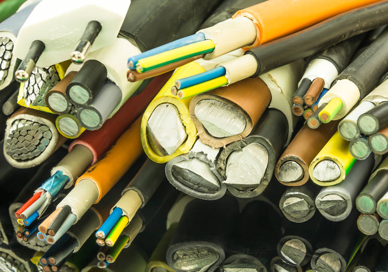
Automotive assemblies today are full of various electrical wires and cable harnesses required to transmit power and other signals to control engine operations, the on-board diagnostic computer, fuel injection system, auxiliary lights, dashboard controls, and the increasingly common infotainment system. These wires are routed through sleeves, taped with fabric tape, and inserted through panels. Due to this level of processing and handling there is a high risk of wire damage or breakage. Additionally, since the electronics are located in automobiles, they are often subjected to both high and low temperatures.

Our Solution
Insulation Testing

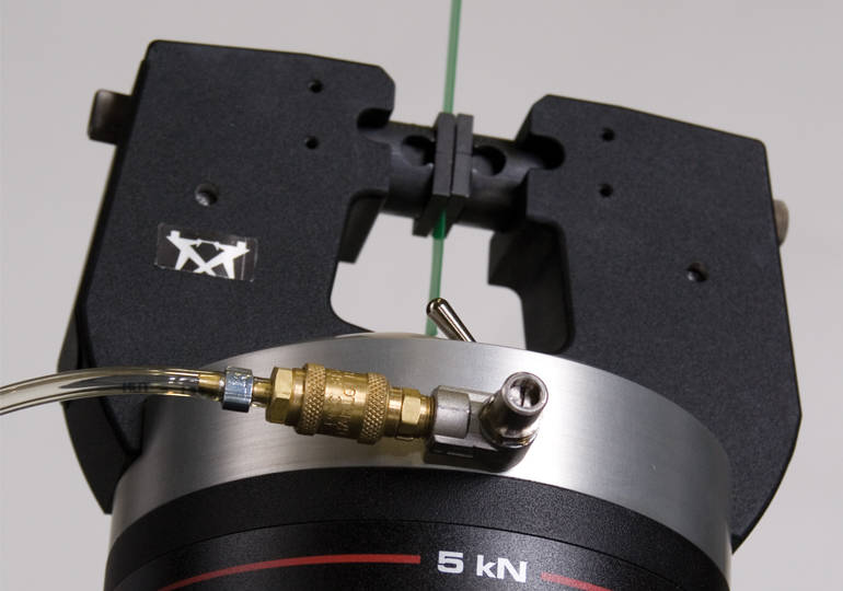
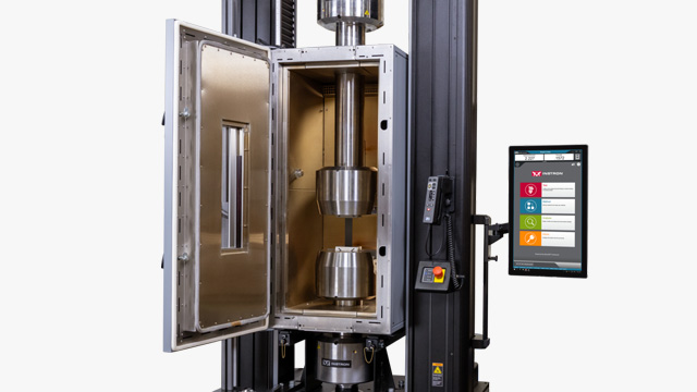
Instron offers a variety of gripping solutions that are designed to clamp or hold specimens of various sizes. Pneumatic grips are the most commonly used gripping solution for securely holding wires and harnesses. Additionally, a variety of environmental chambers are available and can be set or controlled within Bluehill® Universal software.  Features such as pre-heat and pre-cool are available to ensure the test is run at the specified temperature limits. Instron’s Custom Solutions Group is committed to working with customers on applications that need measurements of electrical signals while testing is performed. Instron’s testing systems offer various communication channels that enable Bluehill Universal to present the electrical signal on the graph along with the force vs. displacement curve.


Contact Us to learn more about our automotive solutions.

Button and Switch Compression Testing

Button and Switch Compression Testing

The Challenge
Button and Switch Compression

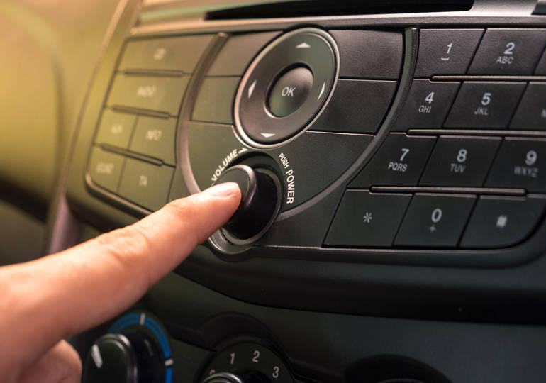
In today's automobiles, a single click of a button or switch is used everywhere, including starting the engine, dashboard controls for entertainment and diagnostic information, and advanced door locking systems. This makes it critical to test the functionality of buttons and switches as the risk of a defective button could be very high, the driver not being able to enter or turn on the vehicle. Mechanically testing buttons is mainly compression testing to understand how much force is required to push a button to engage the electrical signal. This is also known as tactility testing of buttons where OEMs are interested in testing to determine the "feel" of a button.

Our Solution
switch testing

Instron offers various XY stages that can move to test multiple buttons on the same specimen. Standard and custom solutions are available to hold specimens securely during testing.  Instron’s Custom Solutions Group is committed to working with customers on designing probes of different materials and sizes based on specimen and application requirements, in addition to the various standard probes offered.  Instron also offers a multiple point compression software solution strictly designed for testing buttons and switches at high speed, parameters include button height and return height, eliminating long travel times.

Contact Us to learn more about our automotive solutions.

Terminal Strength Test

Terminal Strength Test

The Automotive Electronics Council (AEC) has defined standards that are critical for qualifying electrical components used in automobiles. Due to the exponential increase in applications of microelectronics in automobiles, these standards are of extreme importance. AEC-Q200-006-REV (A) defines the standard for verifying component terminal strength in order to withstand axial stresses that are likely applied from the manufacturing process of finished printed circuit boards (PCBs). Electronics assembly manufacturers and OEMs are interested in understanding the solder joint strength of leads of a surface mount device (SMD) bonded to a PCB or other substrate.

THE CHALLENGE

The standard requires a force to be applied on the component axially for 60 seconds, which results in shearing the component. This force should be applied gradually, and should not induce shock on the component.

Our Solution

Instron® offers a dedicated terminal strength shear fixture that can be used in single or dual column universal testing systems to meet the AEC Q200-006 (A) standard. The fixture has the capabilities to hold a finished PCB in position and shear the target SMD. The adjustable holder of this fixture can account for the various sizes of PCBs, and the linear rail helps the operator to center the shear tool on the component. Different sizes of shear tools are offered based on the dimensions of the SMD.Bluehill® Universal software is used to create test methods as per the standard requirements.
Exhaust Mount Fatigue Testing

Exhaust Mount Fatigue Testing

THE CHALLENGE

Engine Mount

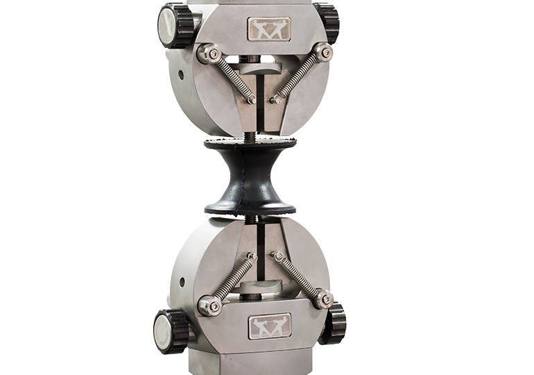
With increasing customer expectations for a quality, reliable product, there is a need to fully test all components.  Rubber mounts, such as those used to connect a vehicle’s engine and transmission to its chassis are required to reduce the transmission of vibrations, protecting the rigid frame and leading to a more comfortable ride.  The elastomeric material used in these components tends to naturally degrade. Simulating real-life conditions is critical to ensure the component can meet the designer’s expectations.  Choosing the correct control parameters required to perform this type of test reliably can be challenging and requires a high-performance test instrument.

THE SOLUTION

Fatigue Testing

Engineers began using ElectroPuls® test instruments to easily perform advanced fatigue tests to understand the fatigue life of rubber mounts. These tests not only validate the component by simulating real-life road conditions but also give insights into the damping characteristics of the material. The mounts were tested at different displacement amplitudes using frequency sweeps to represent the different conditions to which the components are subjected. Choosing the correct control parameters for this type of test is made simple thanks to the patented Stiffness Based Auto Tuning of the ElectroPuls, which automatically optimizes the correct control parameters in seconds. Because Instron® provides simple to use software with built-in DMA calculations, it is quick and easy for users to setup and run tests, saving more time to analyze the data.

Chassis and Body High Strain Rate Testing

Chassis and Body High Strain Rate Testing

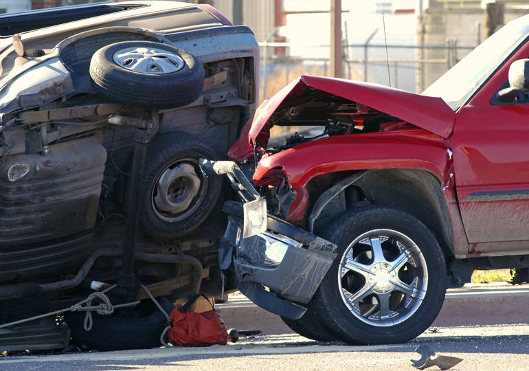
In the automotive sector, development in chassis and body of vehicles is driven by two main aspects, safety, and lightweighting. As the body is the first point of impact during a car crash, modern designs have incorporated features such as crumple zone to absorb most of the initial impact, reducing the force that will reach the passengers. With this in mind, it is essential to understand material behavior under high strain rate, especially during development cycles of metals, alloys, and composites that may be used in chassis or body design. On the other hand, lightweighting provides better fuel economy for the car, decreases component wear and hence provide a much more competitive product overall. Therefore, characterizing how material properties change under high strain rate is important in order to find the optimum design maximizing safety and lightweighting.

Sheet Metal High Strain Rate Testing

The ChallengeChallenge

When considering the crashworthiness of components, testing in high strain rates is essential. As investigated by numerous research, mechanical properties of materials differ drastically under quasi-static conditions and high strain rates. Therefore, accurate data on strain rate dependence of material behavior will provide more realistic computer simulation and evaluation of crashworthiness of structures, whether it is during the development of new alloys or testing automotive components.

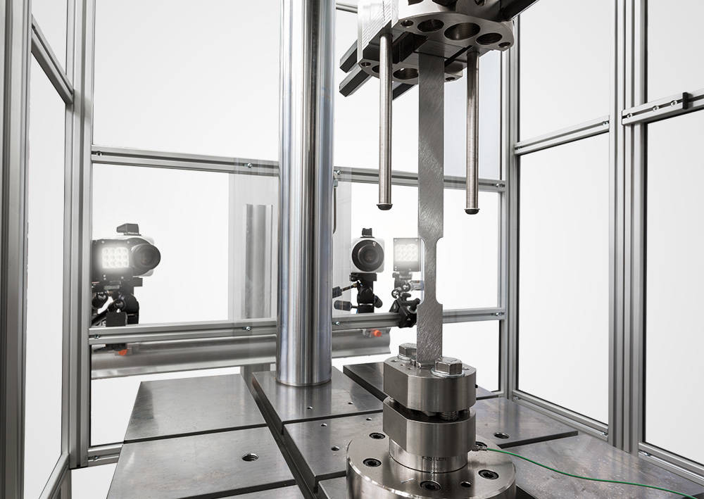
Our SolutionVHS High Strain Rate with DIC Camera Setup

To meet the challenges of high strain rate testing, Instron has been the market leader in manufacturing high strain rate testing machines for over 20 years, advancing high strain rate research and testing capabilities on metals with suitable technologies. For testing metals and high-performance alloys, Instron offers a range of VHS systems that can perform tests that will be suited to your application up to a maximum test velocity of 25 m/s, which translates to testing conditions from quasi-static up to a strain rate of 1000/s. Instron also offers fast jaw or slack rod tensile gripping solutions to ensure gripping at test velocity and DIC integration that will provide non-contact strain measurement with the capacity for dedicated strain gauge channels.


Composite High Strain Rate Testing

The ChallengeComposites Laminates Compression Challenge

When conducting material research for lightweighting, composites are good alternatives to conventional materials such as steel and aluminum, as composites, in general, have a high strength to weight ratio. However, due to the nature of the material being more complex structurally, they possess very different mechanical properties when subject to high strain rate. In conjunction with manufacturing limitations in making dog bone specimen, testing of composites under high strain rate is more complex than that of metals and alloys. Therefore, having an accurate and reliable testing machine and a gripping solution is essential in driving composite research in the automotive industry.

Our SolutionHigh Strain Rate VHS Testing System with Fast Jaw Grips

For testing composites, Instron provides a range of 8800 High Strain Rate that are suitable for testing composites. Instron also offers fixtures that will be compatible with a composite specimen. Using plasma spray, dowel pin, and pyramid jaw faces, it will provide ample gripping force without inducing surface tear on the composite specimen, in turn preventing failure near grip face. Also, as strain gauges cannot be welded onto composite materials, a high strain rate testing machine with full DIC integration is invaluable in providing a non-contact solution to perform accurate strain measurements.

Seatbelt High Strain Rate Test

Seatbelt High Strain Rate Test

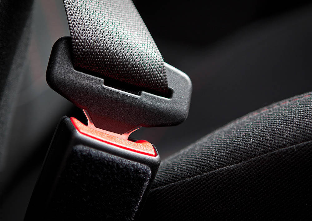
In the automotive field, the safety of passengers is key and many research and development efforts have been put to ensure each critical safety component is tested and up to standard. Seatbelts play a big role in car safety as it decreases the momentum of passengers, reducing the force of secondary impacts with interiors and prevents passengers from being ejected from a vehicle in a crash or a sudden stop. 

The Challengecar seatbelt

In the automotive field, the safety of passengers is key and many research and development efforts have been put to ensure each critical safety component is tested and up to standard. Seatbelts play a big role in car safety as it decreases the momentum of passengers, reducing the force of secondary impacts with interiors and prevents passengers from being ejected from a vehicle in a crash or a sudden stop. This greatly reduces the risk of major injuries when used in conjunction with other safety features such as airbags and shock absorbing mechanism in dashboards and steering wheel columns. In addition to tensile strength and durability of seatbelts, the behavior of seatbelt materials under high strain rate is a topic of interest, as polymers exhibit different mechanical properties under high strain rate impact during crashes without breaking.

Our SolutionHigh Strain Rate VHS Testing System with Slack Rod Grips

In order to meet the challenges of characterizing high strain rate behavior of seatbelt material, Instron developed a long stroke variation of the High Strain Rate Testing System VHS. Its static capacity sits at 35 kN, dynamic capacity at 50 kN with a nominal stroke of 600 mm and a maximum test velocity of 20 m/s, which is sufficient for more compliant polymeric components. We have also developed accompanying custom grip fixtures and incorporating DIC onto the system as a non-contact strain measurement system, offering an integrated solution for testing compliant materials under high strain rate.


Learn more about our automotive solutions

Soft Tissue Testing

Soft Tissue Testing

The Challenge

Skin

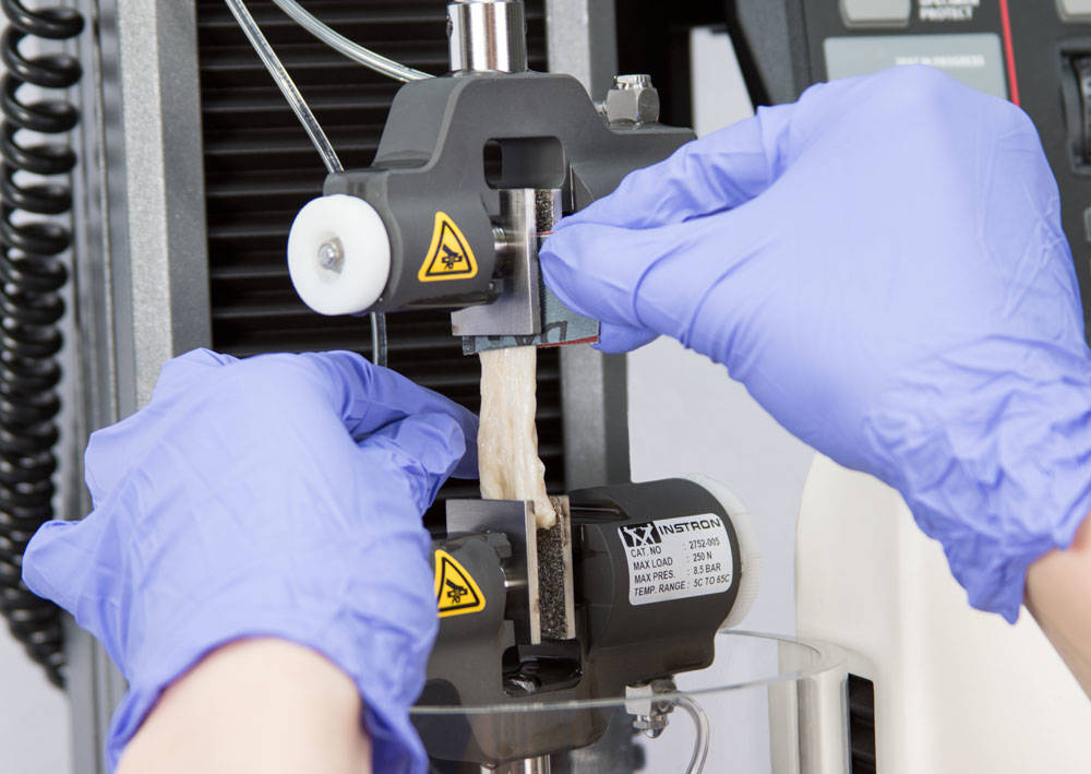
Testing soft tissues, such as skin, tendons, ligaments, and others, presents many challenges. Specimens of this type are delicate; hence they break at low forces. Gripping soft tissues can also be problematic given that these specimens are small, slippery, and compliant in nature. In addition, soft tissues are viscoelastic and often require accurate elongation or strain measurement to properly understand the material properties. Typically, in vivo conditions are needed to test soft tissues, which calls for the test to be performed at body temperature and in a hydrated state. This requires the testing equipment and fixture to be corrosion resistant and "waterproof" to avoid damaging the sensitive electronics of the testing system.  

Our Solution 

Soft Tissue Testing

For testing at physiological conditions, the Instron® BioBath is an ideal solution for keeping a specimen fully hydrated in a saline solution and at 37°C. The BioBath uses a closed-loop temperature control measurement, which can be fed directly into the test system's software to accurately track specimen temperature, in addition to mechanical test data. Pneumatic grips are recommended for consistent clamping pressure that the user can vary up to 90 PSI. A high friction surface is often needed to grip slippery biomaterials to avoid specimen slipping. To avoid this, we recommend using a metallic high friction finish known as surfalloy on the grip face, but grit sandpaper is also a viable option. A stainless steel tray, such as the BioTray, can help protect the system's electronics from damage in the case of spills or messy specimens.

Solutions pour les essais de barres darmature

Solutions pour les essais de barres darmature

rebar-testing-on-electromechanical-testing-system-1.jpg

La production mondiale de la construction devrait augmenter de plus de 70 % pour atteindre 15 billions de dollars à léchelle mondiale dici 2025. Les projections de taux de croissance impliqueront de nouveaux ponts, routes, barrages, tunnels, stades, etc. Toutes ces structures nécessiteront des barres darmature (ronds à béton) noyées dans le béton pour améliorer la résistance à la traction.

Diverses normes de produits pour les barres d’armature renvoient à une ou plusieurs normes d’essai internationales, et des directives d’essai sont largement disponibles. Les systèmes Instron sont conformes aux normes suivantes : ISO 6892-1:2009, ISO 15630-1 ; ASTM E8M: 2013, A370, A615 ; AC133 ; BS 4449 ; GB 1499 ; et JIS G3112.

Le guide Barres d’armature en acier : un guide d’essai de traction est disponible en complément des normes de produits et d’essais et fournit des explications sur les points couramment mal interprétés par l’utilisateur.

Lessai des barres darmature présente de nombreux défis, notamment : les éprouvettes irrégulières et/ou pliées ; les ruptures violentes par traction ; la mesure de la déformation et de lallongement ; lobtention de résultats de traction répétables et précis ; les essais de pliage ; et les essais cycliques pour les coupleurs de barres darmature.

Efficiency

Globally, testing of sheet metal material is typically performed using a ‘traditional’ testing setup requiring a large amount of operator input. By utilizing some cost-effective changes, the efficiency of your testing regime can be greatly improved.

Setup for Efficiency

Using the latest Bluehill® Universal software, small modifications can be made to the testing protocol to gain incremental improvements. These could include creating a prompted test method to ensure only valid information is prompted for each test, minimizing wasted time needed to monitor or change non-value inputs.

Alternatively, integrating new or existing specimen measuring devices to work autonomously with the software instead of manually inputting values can save a great deal of time.

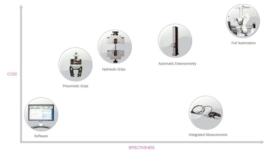
Cost versus Effectiveness

Switching from manual grips to either pneumatic or hydraulic grips will automate the gripping process. This significantly reduces the time it takes to close the upper and lower grip, and also ensures less variation in test results are caused by operators manually clamping each grip.

Automatic extensometers can save a large amount of time for each test since they require no manual setup between tests. Some extensometers may need to be removed during the test to prevent damage to the device. Therefore, time savings will also be achieved by using an automatic device that is designed to remain on the specimen through fracture or automatically removed.

The graphic below demonstrates a typical test cycle time comparing only the effect of extensometer choice:

Automatic Extensometers can save you time

Struggling to justify new purchases? Talk to Instron® to see where the most cost-effective changes could be made with your existing equipment.