Drop Tower Impact Testing of Rocks and Stones

Drop Tower Impact Testing of Rocks and Stones
We have recently been in contact with a customer interested in a non-standard, but extremely interesting, way to perform impact tests. This company is specialized in the development of systems for selective fragmentation of various solids, especially in the mining and geosciences circuits. In these environments, improved methods for mineral comminution are continually being sought, pursuing the goal of achieving the required size reduction at a lower energy consumption level than conventional technology allows. Comminution is probably the largest energy consumer in most mine sites, with major implications for costs as well as environmental pollution. Applying different working conditions with their units they are able to pre-weak the rock or the stone to be comminuted. To understand how much their process is affecting the raw material, we suggest them a basic impact test by a means of a drop tower.

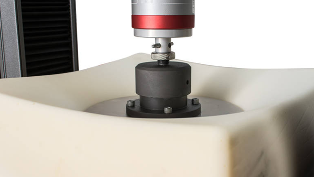
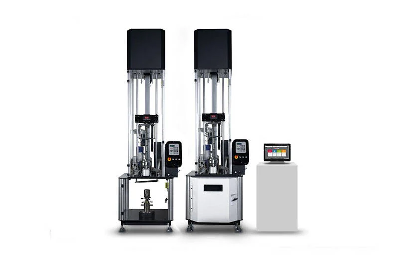
To help them to completely characterize the process, we have offer a 9450 drop tower equipped with a special support and a dedicated tup plus insert. The pre-weakened rock/stone will be placed for the test on the dedicated flat support. This support is connected to a reinforced adjustable height stand, which allows the proper positioning of the specimen for the impact. A dedicated tup, including a special reinforced flat insert, is used in combination with a reinforced tup-holder to impact the stone to be pulverized. Just selecting a specific mass and some basic test conditions (like the impact velocity or a drop height), it is possible to deliver on the specimen a well known amount of energy. The antirebound system is able to catch the tup preventing a second impact on the specimen. The weakened specimen will absorb a part of the impact energy fragmenting in many small pieces. The special box that is covering the impact area will allow to contain all pieces generated during the test, in order to perform further analysis and checks on the tested specimen.

To improve the understanding of the fragmenting process, is also possible to exchange the un-instrumented tup with a special one including a force sensor. The sensor, used in combination with a DAS and its related Bluehill software, will allow acquire the whole impact event and to perform more deeper analysis and studies.

Literature

9400 Series Drop Tower Brochure

Instron Drop Towers are used to develop, fine tune, and validate material models. Testing materials under real impact conditions is a crucial step prior of product design. Using the characterization data obtained with the Instron 9400, coupled with customer supplied high-speed video, you can have confidence in your results and deliver new materials to your customers faster. Our Drop Tower impact systems, fixtures, and tups are designed to meet a wide range of applications and testing standards including: ISO, ASTM, ANSI, Airbus, Boeing, BSI, DIN, EN, FDA, Ford, GM, JIS, NASA, GOST, and more.

  • Produits
  • 02/05/2020
  • 763.1 KB

9400 Series Dashboard Brochure

Bluehill® Impact is built from the ground up for touch interaction. The Operator Dashboard features large touchpoints to make the user experience simpler and smarter. Easy-to-understand icons and workflows make it easy to train new or experienced users, simplify operator training, and allow you to start testing even faster than ever before

  • Produits
  • 08/01/2019
  • 2.35 MB
Chassis and Body (Translated to fr)

Chassis and Body

Bumper Impact Testing

To understand the impact resistance properties of bumper materials, a series of tests on specimens should be conducted, in plaque form, at varying impact energies, velocities, and temperatures.

Learn More

Chassis and Body High Strain Rate Testing

As the body is the first point of impact during a car crash, modern designs have incorporated features such as crumple zone to absorb most of the initial impact, reducing the force that will reach the passengers.

Learn More

Composite Laminates Compression After Impact Testing

Compression After Impact test (CAI) is used to define the damage resistance of composites after an Impact event. An impact on composite laminate panel may result in no visible external damage, but it may generate a dramatic reduction of compressive strength. The design of automotive parts using composite materials should consider the effects of impact on the material properties.

Learn More

Composite Laminates Tensile Testing

A wide range of new materials are being used to decrease the weight of vehicles and reduce emissions. Of these new materials continuous carbon fiber polymer composites offer great potential for producing lightweight structures, however, there are many barriers to their widespread adoption.

Learn More

Crash Simulation

Over the past 20 years, the importance of occupant protection in the development of automobiles has greatly increased. Tighter legal requirements and consumer protection programs have led to significant innovations in the area of active and passive safety.

Learn More

Exhaust Line Durability Test

The investigation of the durability of complex assemblies and structures such as vehicle exhaust lines is an essential part of the vehicle development processes conducted by automotive manufacturers and component suppliers.

Learn More

Exhaust Mount Fatigue Testing

Instron® provides simple to use software with built-in DMA calculations, it is quick and easy for users to setup and run tests, saving more time to analyze the data.

Learn More
Fatigue Testing

Fatigue Testing

Fatigue performance has always been important in automotive design, where the sources of cyclic loading and vibration are many and varied.

Learn More

Full Vehicle Testing

Loads caused by driving maneuvers, e.g. Longitudinal, braking and lateral forces can only be detected by a multi-test system test stand, such as full vehicle test rig.

Learn More

Electronique


Automotive
»
Electronique
»
Page 3


Des appareils grand public au nombre croissant de systèmes électroniques dans les véhicules d'aujourd'hui, les composants électroniques doivent résister aux contraintes mécaniques de la fabrication, de l'assemblage et de l'utilisation quotidienne. Les solutions de test Instron aident les fabricants à vérifier la force d'adhérence, la fiabilité des connexions et la durabilité, conformément aux normes industrielles clés.

Vous recherchez des tests courants tels que le cisaillement par recouvrement, l'arrachement de broches et le test de pelage ? Explorez nos applications de test électronique à usage général.

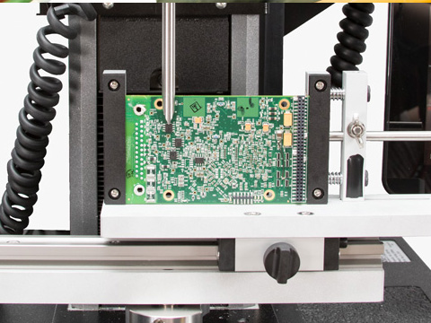
L'AEC-Q200-005 Rév A définit la norme pour vérifier la force d'adhérence des composants montés en surface sur les cartes de circuits imprimés (PCB) finies, en testant leur capacité à résister aux forces de flexion, de déformation et de traction.

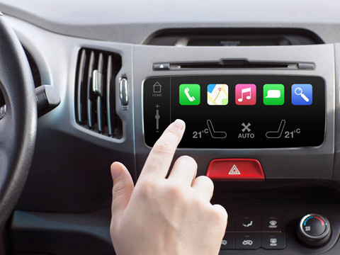
Les boutons et les interrupteurs contrôlent presque tout dans les véhicules d'aujourd'hui, du démarrage du véhicule aux commandes du tableau de bord, de l'infodivertissement et du verrouillage des portes. Les essais de compression mesurent la force d'actionnement et la sensation de chaque bouton ou interrupteur, aidant les fabricants à vérifier des performances constantes tout au long de sa durée de vie.

Alors que les écrans d'infodivertissement et les écrans tactiles deviennent la norme dans de nombreux véhicules, les fabricants doivent comprendre leur fiabilité mécanique. Les essais de panneaux d'affichage évaluent la façon dont les écrans et les panneaux réagissent aux forces qu'ils subissent pendant l'assemblage et l'utilisation quotidienne.

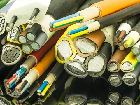
Les véhicules d'aujourd'hui contiennent un nombre croissant de fils électriques et de faisceaux de câbles qui transmettent l'énergie et les signaux aux commandes du groupe motopropulseur, aux diagnostics embarqués, à l'éclairage, aux commandes du tableau de bord et aux systèmes d'infodivertissement. Les essais de traction vérifient la résistance des fils et de leur isolation, contribuant ainsi à réduire le risque de pannes électriques.

L'Automotive Electronics Council (AEC) a défini des normes essentielles pour la qualification des composants électriques utilisés dans les véhicules. Avec l'augmentation rapide des microélectroniques dans les véhicules, les essais de résistance des bornes selon ces normes contribuent à garantir que les bornes des composants peuvent résister aux forces mécaniques de l'assemblage et de l'utilisation.

Parlez à un expert Instron

Vous ne savez pas quel test convient à votre application électronique ? Parlez-nous de vos exigences de test et nous vous aiderons à trouver la bonne solution — sans tâtonnement.

Parlez à un ingénieur d’applications

Parlez-nous de vos besoins d’essai et nous vous aiderons à configurer le bon bâti, la bonne cellule de charge, les mors et le logiciel pour votre laboratoire. Veuillez remplir le formulaire ci-dessous et nous vous répondrons sous 1 à 2 jours ouvrés. Pour une réponse plus rapide, appelez le +1-800-473-7838 ou le +1 781 828 2500 si vous êtes en dehors des États-Unis.

Veuillez fermer cette fenêtre et
accepter les cookies
pour afficher et remplir le formulaire.

Drivetrain and Suspension

Drivetrain and Suspension

Drivetrain and Suspension

Roues et pneus


Automotive
»
Roues et pneus
»
Page 3


Roues et pneus

Les systèmes de test de fatigue à haute température incluent la fatigue à bas cycle (LCF), la fatigue thermomécanique (TMF) et les essais électro-thermiques (ETMT). Les systèmes LCF évaluent la performance des matériaux dans des conditions isothermes élevées lorsqu’ils sont soumis à de fortes charges et à des déformations plastiques. Les systèmes TMF et ETMT simulent les effets complexes du cycle thermique combiné à la charge mécanique, normalement ressentie par les turbines à gaz et équipements similaires pendant le fonctionnement. Tous les systèmes de test de fatigue à haute température Instron sont des packages entièrement intégrés qui permettent à nos clients de réaliser des tests rapidement et efficacement, en conformité avec toutes les normes applicables.

Cette note d'application explore la rhéologie des composés de caoutchouc de pneumatique et les défis auxquels sont confrontés les fabricants lors de l'évaluation de la viscosité, du comportement d'écoulement et des caractéristiques de gonflement à la filière. À l'aide d'un rhéomètre capillaire CEAST SR20, l'étude mesure la viscosité en fonction du taux de cisaillement et le gonflement de l'extrudat afin de mieux comprendre le comportement des élastomères lors de la mise en œuvre. Les résultats démontrent un comportement d'écoulement non newtonien, une excellente répétabilité et l'intérêt de la mesure du gonflement par laser pour optimiser les formulations de caoutchouc de pneumatique et garantir une production cohérente et de haute qualité.

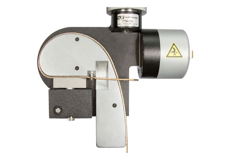
Les câblés pour pneumatiques sont des matériaux de renforcement extrêmement résistants, ce qui les rend difficiles à serrer pendant les essais sans provoquer de défaillance prématurée. Les mors pour câblés d’Instron sont conçus avec des faces lisses et incurvées qui répartissent uniformément les contraintes le long de l’éprouvette, réduisant considérablement les ruptures aux mâchoires et garantissant des résultats plus précis et répétables.

Découvrez les défis spécifiques des essais de traction sur les matériaux de pneus élastomères, où l’allongement extrême, les variations de température et l’amincissement de l’éprouvette peuvent compromettre la précision. Cette présentation explique pourquoi les extensomètres à pince traditionnels ne conviennent pas et met en avant des solutions d’extensométrie sans contact et à grande course — telles que l’AVE 2 et la série XL — qui assurent une mesure fiable de la déformation jusqu’à la rupture. Elle aborde également les difficultés de préhension courantes avec les éprouvettes en caoutchouc et décrit des options de mors pneumatiques et auto-serrants qui empêchent le glissement et les ruptures prématurées, aidant les fabricants à obtenir des résultats constants et conformes aux normes.

Interior

Interior

Automotive » Interior » Page 3

Interior

Safety Systems

Safety Systems

Automotive » Safety Systems » Page 3

Safety Systems

Adhésion

Adhésion


Automotive
»
Adhésion
»
Page 3


Les procédés d’assemblage sont essentiels à l’intégrité structurelle et à la sécurité des ensembles automobiles. Des liaisons adhésives et soudures plastiques aux fixations métalliques à haute résistance, chaque méthode d’assemblage doit être rigoureusement testée afin de garantir ses performances en conditions réelles. Instron propose une gamme complète de solutions d’essais pour aider les constructeurs automobiles et leurs fournisseurs à caractériser les propriétés mécaniques de leurs technologies d’assemblage — des essais quasi-statiques à l’évaluation à grande vitesse de déformation.

Alors que l’allègement favorise l’adoption de nouveaux matériaux dans la conception automobile, la technologie d’assemblage par collage joue un rôle de plus en plus crucial. Cette page présente les solutions d’essais Instron pour les applications automobiles d’adhésifs — des essais de cisaillement par recouvrement et de pelage à la ténacité à la rupture, la fatigue et les essais d’impact selon l’ISO 11343 et d’autres normes clés.

Comprendre le comportement des joints soudés, boulonnés et adhésifs dans des conditions de vitesse de déformation élevée est essentiel pour valider les simulations de collision et développer des structures de véhicules plus légères et plus résistantes. Cette page présente les solutions d'essais à vitesse de déformation élevée d'Instron pour les structures automobiles assemblées, notamment le système Instron VHS et une large gamme d'accessoires de montage et de montages personnalisés.

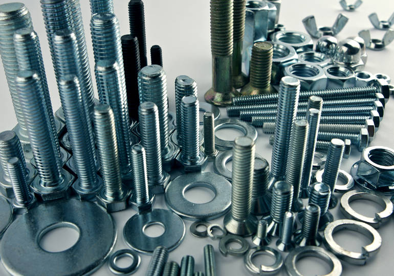
Les boulons métalliques sont utilisés en très grandes quantités dans l'ensemble de la fabrication automobile, des assemblages structurels à haute résistance à la fixation de composants légers. Cette page présente les solutions d'essai d'Instron pour l'ensemble des défis liés aux essais de boulons — y compris le contrôle qualité pour la production en grand volume, les essais de boulons courts, les essais de charge d'épreuve d'écrou, la mesure de déformation et les essais de résistance au cisaillement.

À mesure que les composants automobiles sont de plus en plus souvent fabriqués en plastique, garantir l’intégrité des liaisons de soudure plastique est essentiel, à la fois pour le développement produit et le contrôle qualité. Cette page présente les solutions d’essais de traction Instron pour les assemblages soudés en plastique, y compris des options de serrage déporté pour les éprouvettes avec languettes non linéaires et des plaques d’essai de composants pour des géométries non standard.

Vous ne savez pas quelle solution d’essais convient le mieux à votre application d’assemblage ?

Engine

Engine

Automotive » Engine » Page 3

Engine

Electrode Anode Testing

tack and peel testing fixtures

Electrode Anode Testing for Electric Vehicle Batteries

There are multiple ways in which batteries can fail. One of the most common modes of failure is caused by the electrode coating material cracking or delaminating from the current collector. This cracking or delaminating is typically caused by the constant charging and discharging of the battery as well as by mechanical loading of the battery in use. It is critical to understand the adhesion strength and longevity of electrodes to ensure that a battery does not fail before the end of its predicted life cycle.

As battery manufacturers work to understand the adhesive properties of their cathode and anode materials, many are also introducing new electrode makeups in an effort to increase the safety and energy density of batteries. Most of these changes are to the anode material with additions such as silicone, which requires further testing and analysis. It is critical to understand how electrode adhesion is influenced by different binders and elements. The three types of testing most commonly used to characterize the adhesive properties and monitor production material for electrodes are 90° peel tests, 180° peel tests, and tack tests.

180° Peel Test

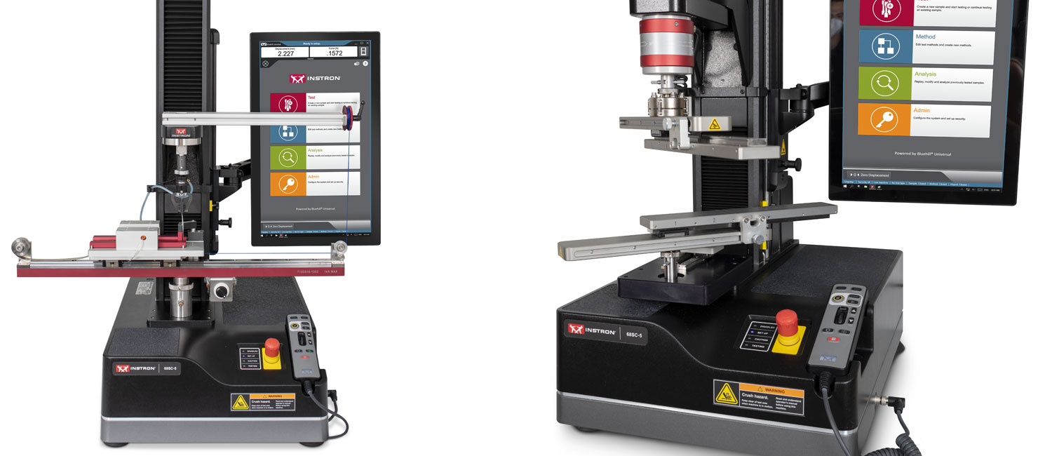
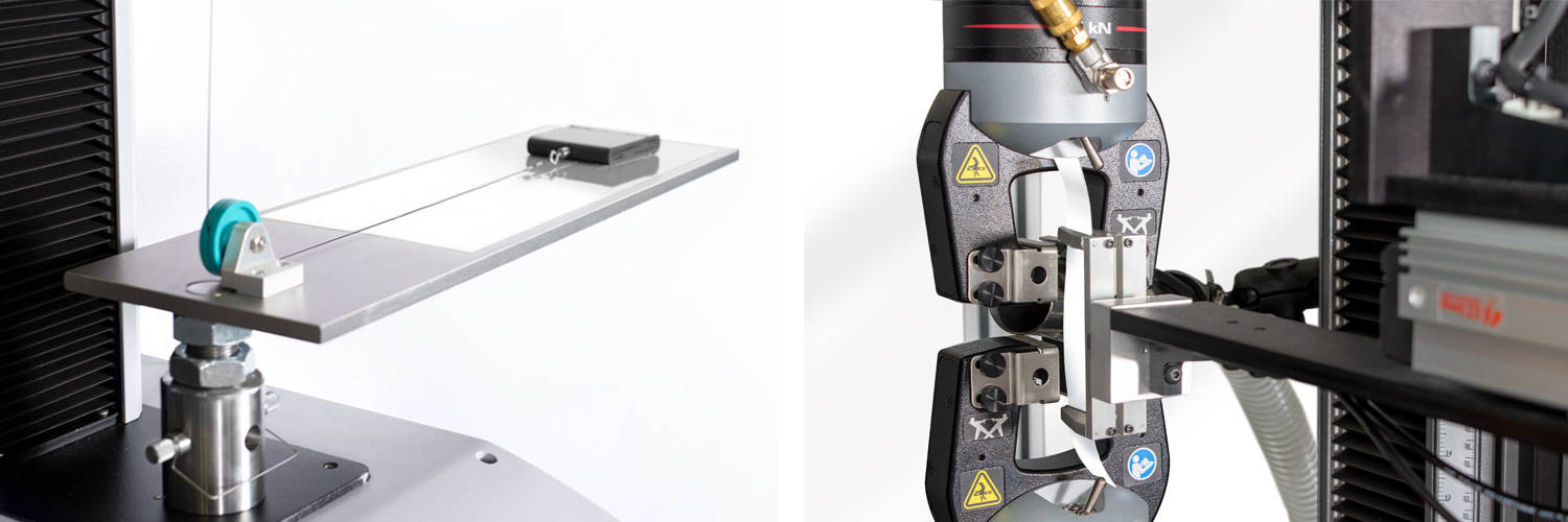
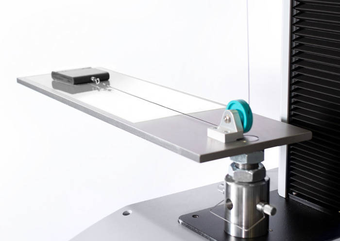
The most commonly performed peel tests are 90° and 180° peel tests. 180° testing has an advantage over 90° testing in simplicity of setup and ease of alignment. This testing can be done using low force grips and load cells along with a substrate that helps the flexible material maintain proper alignment during testing. It is best to consider pneumatic grips and a metal substrate to ensure high throughput and a proper 180° peel throughout each test.

electrode test

90° Peel Test


90° peel testing is commonly seen as an alternative to 180° degree peel testing. The 90° peel test generally involves slightly higher loads than the 180° peel test and can be set up more quickly because it often does not require a substrate. Instron’s most common solutions for this testing are a standard 90° peel fixture or a pneumatic peel fixture designed specifically to test the adhesion of electrodes. The pneumatic 90° peel fixture was developed specifically for electrode adhesion testing and provides improved repeatability and throughput while also aiding the operator in consistent specimen placement and alignment at 90°. For the upper fixture, a pneumatic grip optimizes throughput and repeatability and is recommended for testing delicate materials.

Tack Testing

A tack test is an electrode adhesion test that has been backed by researchers as an additional way to test the adhesion of electrodes to a battery's current collector. Instead of slowly peeling electrodes from the current collector, a tack test focuses on the adhesion strength of an entire predetermined area of electrodes, allowing for quicker evaluation of electrode adhesion over a large area. Instron’s tack testing fixture is designed for ease of specimen preparation as well as high throughput and repeatability. It features predetermined contact areas in addition to a spherically seated and lockable upper fixture, which ensures parallelism between both fixtures. Due to the fast speeds of this testing, a testing system with a very high data rate collection will ensure the best possible results and throughput.


Separator Film Testing for Electric Vehicle Batteries

separator film testing

Separator Film Testing for Electric Vehicle Batteries

A separator is a membrane that separates a battery cell's anode from its cathode. Separator films are a critical part of lithium-ion batteries and other liquid electrolyte batteries. The polymers used for these films must be strong enough to withstand the winding operation during assembly as well as plating of lithium on the anode in an uneven manner due to extensive use. Issues with the selection of the cell separator materials can compromise battery integrity and increase the potential for internal short circuits, leading to thermal runaway, fire, and even explosions. Safer and stronger separator material more effectively prevents contact between the anode and cathode, while thinner material helps reduce the weight of each battery and improve energy density.

The main tests performed to evaluate the mechanical properties of separator film are tensile, puncture, and coefficient of friction tests. Tensile and coefficient of friction testing are critical for ensuring the separator film can withstand manufacturing of the battery, while puncture resistance is a crucial mechanical property used to assess and select the material with the best performance, while reducing the thickness, number of layers, and weight. UL 2591 (Component certification for lithium-ion battery cell separators) was specifically designed
to develop a comprehensive approach to cell separator testing in order to address safety
concerns associated with separators becoming progressively thinner and lighter due to industry trends.


Tensile Test

Tensile testing ensures that separator film can withstand all tensile forces applied during manufacturing and throughout the service life of the battery. There are several standards suitable for tensile testing polymer separators, including ASTM D882 and ISO 527-3. Ensuring proper specimen alignment, insertion, and grip operation are necessary for best repeatability and throughput, as well as to avoid possible damage to a specimen before testing. Instron offers a variety of solutions for tensile testing battery separator films, with both affordable and premium tiers of products designed to provide superior accuracy and throughput for labs requiring them. Testing these materials in accordance to ASTM D882 can be very beneficial for quality control checks as well as during R&D when trying to determine the optimal separator film solution. Additionally, as is the case for many other thin film materials, separator film is anisotropic and so is recommended to be tested in multiple different cutting/testing directions.


Puncture Test

Separator film must be strong enough to withstand punctures from dendrites that form with extensive battery use. This is critical for ensuring the safety and longevity of each cell throughout the lifespan of the battery. Ensuring proper specimen tautness and alignment of the upper probe are critical for this application. ASTM F1306 outlines the puncture testing of flexible barrier films to characterize the material response when a 3.2 mm diameter probe is driven into a clamped specimen. EN 14477 is another standard that characterizes the puncture resistance of thin film materials, however, it uses a smaller probe (0.8 mm) compared to ASTM F1306. High-speed puncture resistance testing to ASTM D3763 can be determined by use of Instron's 9450 Series drop tower.


Coefficient of Friction Test

Tight winding creates mechanical loads between the separator film and the electrode coating, and understanding the coefficient of friction can ensure that proper winding processes occur in production. It is common to use ISO 8295 and ASTM D1894-14 as guidance for this testing.

coefficient of friction battery separator film testing 


Automation

Automation systems from Instron introduce a new level of productivity for battery testing. As battery production volumes continue to increase, throughput and efficiency are critical to keep up with demand. Utilizing an automation system with the recommended equipment for each application can free up operators and maximize throughput, while maintaining optimal results.

Foil Testing for Electric Vehicle Batteries

copper foil in tensile testing machine


Foil Testing for Electric Vehicle Batteries


ev battery icon

The electric vehicle battery industry is constantly improving the energy density and safety of their products. A significant focus is on the aluminum and copper foils used in each cell as current collectors. Thinner foil helps to reduce battery weight (contributing to energy density), and longer/wider foil increases production efficiency (contributing to cost reduction). However, as innovation drives foil materials to become thinner, it becomes even more critical to accurately capture their material properties and ensure that adequate quality control measures are in place.

Many companies in the industry are currently working on producing copper foil between 4 and 12 microns thick. However, as copper foil becomes thinner, longer, and wider, improved technology is required to address wrinkling and tearing concerns during production. Given that batteries need to be able to withstand the mechanical loading under normal use, as well as expansion and contraction when charging and discharging over time, the current collector foil must also be able to withstand these factors without yielding. Ensuring that these newer foils are able to withstand the loads required of it during both use and production, increased mechanical testing is needed.

Relevant standards for this application include ASTM E345, EN 546-2, and DIN 50154, which can be used as guidance for testing EV battery foils.

Tensile Test

A standard tensile test is the most appropriate way to determine the mechanical properties of aluminum and copper foil specimens. Typically, elongation at break and maximum load are the key material properties that are calculated in mechanical testing, as these properties help ensure the quality of the foil; whether or not it will be able to withstand the mechanical loading and expansion/contraction in use.

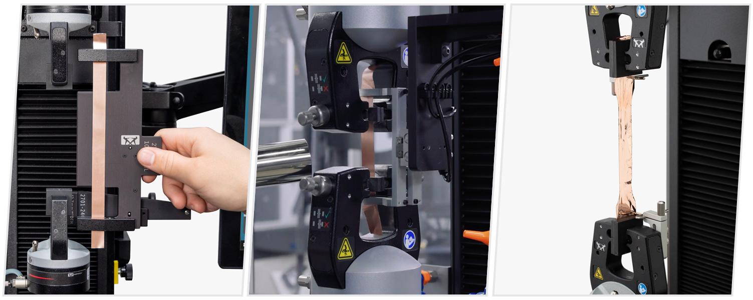
While some standards may call out gripping options, such as wedge action grips, Instron has found that pneumatic side action grips are the optimal solution for foil under 20 microns thick. Pneumatic side action grips offer the ability to fine tune the clamping pressure and they will always provide constant pressure throughout each test. The use of pneumatic grips also improves throughput for these high-volume materials, as quality control labs can test hundreds of specimens per day. An additional factor that must be considered is the type of clamping surface, such as the jaw faces used. The optimal jaw faces to pair with pneumatic side action grips are rubber-coated faces. The soft and pliable rubber is able to adequately hold foil material throughout the duration of a test, while minimizing the stress concentration added by clamping the specimens.

foil testing in universal testing machine


Specimen Preparation and Alignment

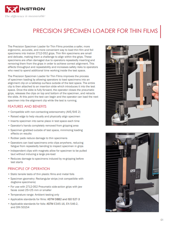
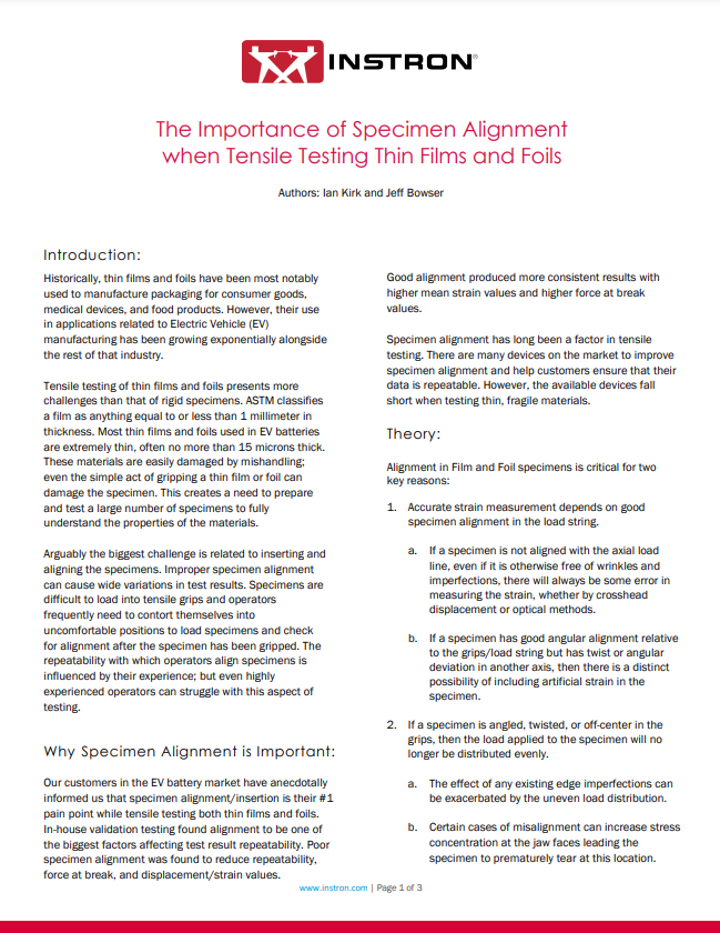
Two of the biggest challenges that come from testing foil material are the preparation and alignment of the specimen. Specimen preparation is extremely critical for such fragile specimens. The better the quality of the cut, the better the quality of the edges will be for each specimen. Poorly cut edges increase the chances of the material breaking prematurely. Premature failure reduces the quality of the test results, and can lead to the need for re-testing.

Specimen alignment is also critical for repeatability and protection of the specimen, as thin foils can be noticeably affected by minor misalignment within the grips. Additionally, having to adjust foils within the grips multiple times can sometimes lead to premature breaks due to the damage caused by clamping and unclamping. We highly recommend using Instron’s Precision Specimen Loader to reduce variability in test results while improving ergonomics and safety.

Automation

Automation systems from Instron introduce a new level of productivity for foil testing. As battery production volumes continue to increase, throughput and efficiency are critical to keep up with demand. Utilizing an automation system with the recommended equipment for each application can free up operators and maximize throughput, while maintaining optimal results.